POLYGON SCANNER FOR LASER PAINT STRIPPING
POLYGON SCANNER FOR LASER PAINT STRIPPING
POLYGON SCANNER FOR LASER PAINT STRIPPING
Create successful ePaper yourself
Turn your PDF publications into a flip-book with our unique Google optimized e-Paper software.
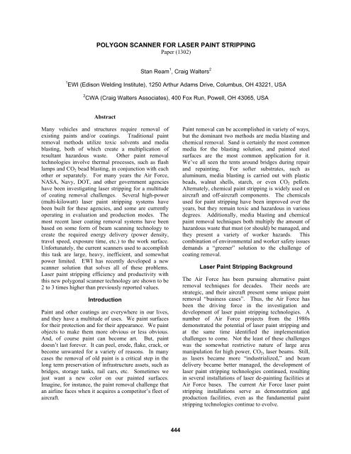
<strong>POLYGON</strong> <strong>SCANNER</strong> <strong>FOR</strong> <strong>LASER</strong> <strong>PAINT</strong> <strong>STRIPPING</strong>Paper (1302)Stan Ream 1 , Craig Walters 21 EWI (Edison Welding Institute), 1250 Arthur Adams Drive, Columbus, OH 43221, USA2 CWA (Craig Walters Associates), 400 Fox Run, Powell, OH 43065, USAAbstractMany vehicles and structures require removal ofexisting paints and/or coatings. Traditional paintremoval methods utilize toxic solvents and mediablasting, both of which create a multiplication ofresultant hazardous waste. Other paint removaltechnologies involve thermal processes, such as flashlamps and CO 2 bead blasting, in conjunction with eachother or separately. For many years the Air Force,NASA, Navy, DOT, and other government agencieshave been investigating laser stripping for a multitudeof coating removal challenges. Several high-power(multi-kilowatt) laser paint stripping systems havebeen built for these agencies, and some are currentlyoperating in evaluation and production modes. Themost recent laser coating removal systems have beenbased on some form of beam scanning technology tocreate the required energy delivery (power density,travel speed, exposure time, etc.) to the work surface.Unfortunately, the current scanners used to accomplishthis task are large, heavy, inefficient, and somewhatpower limited. EWI has recently developed a newscanner solution that solves all of these problems.Laser paint stripping efficiency and productivity withthis new polygonal scanner technology are shown to be2 to 3 times higher than previously reported values.IntroductionPaint and other coatings are everywhere in our lives,and they have a multitude of uses. We paint surfacesfor their protection and for their appearance. We paintobjects to make them more obvious or less obvious.And, of course paint can become art. But, paintdoesn’t last forever. It can peel, erode, flake, crack, orbecome unwanted for a variety of reasons. In manycases the removal of old paint is a critical step in thelong term preservation of infrastructure assets, such asbridges, storage tanks, rail cars, etc. Sometimes wejust want a new color on our painted surfaces.Imagine, for instance, the paint removal challenge thatan airline faces when it acquires a competitor’s fleet ofaircraft.Paint removal can be accomplished in variety of ways,but the dominant two methods are media blasting andchemical removal. Sand is certainly the most commonmedia for the blasting solution, and painted steelsurfaces are the most common application for it.We’ve all seen the tents around bridges during repairand repainting. For softer substrates, such asaluminum, media blasting is carried out with plasticbeads, walnut shells, starch, or even CO 2 pellets.Alternately, chemical paint stripping is widely used onaircraft and off-aircraft components. The chemicalsused for paint stripping have been improved over theyears, but they remain toxic and hazardous in variousdegrees. Additionally, media blasting and chemicalpaint removal techniques both multiply the amount ofhazardous waste that must (or should) be managed, andthey present a variety of worker hazards. Thiscombination of environmental and worker safety issuesdemands a “greener” solution to the challenge ofcoating removal.Laser Paint Stripping BackgroundThe Air Force has been pursuing alternative paintremoval techniques for decades. Their needs arestrategic, and their aircraft present some unique paintremoval “business cases”. Thus, the Air Force hasbeen the driving force in the investigation anddevelopment of laser paint stripping technologies. Anumber of Air Force projects from the 1980sdemonstrated the potential of laser paint stripping andat the same time identified the implementationchallenges to come. Not the least of these challengeswas the somewhat restrictive nature of large areamanipulation for high power, CO 2 , laser beams. Still,as lasers became more “industrialized,” and beamdelivery became better managed, the development oflaser paint stripping technologies continued, resultingin several installations of laser de-painting facilities atAir Force bases. The current Air Force laser paintstripping installations serve as demonstration andproduction facilities, even as the fundamental paintstripping technologies continue to evolve.444
Most of the early, large area, laser paint strippingdevelopment was carried out with CO 2 lasers of onetype or another. Continuous wave, TEA laser, and e-beam pulsed lasers were among those evaluated. Thefar-infrared wavelength of these lasers is attractivefrom the standpoints of absorption by the paint andsubstrate damage resistance, but, as mentioned above,the beam delivery complexity of CO 2 lasersencumbered some of the potential applications.Despite this complexity, the multi-kilowatt powercapability of these CO 2 lasers established attractivebenchmarks for paint removal rates and efficiencies.The paint stripping rates of these demonstrations madethe business cases for laser paint stripping credible,and interest in the technology survived. So, whenrobust, multi-kilowatt, fiber-delivered (1.06-1.07 um),laser power became available in recent years,additional research was undertaken to evaluate this“new” candidate wavelength regime.The physical mechanisms of laser paint stripping havebeen described in a number of ways, includingvaporization, ablation, combustion, multi-photonabsorption, shock removal, etc. Figure 1 shows thesubstantial range of peak power and interaction timesover which laser paint stripping has beenaccomplished.Figure 1. Range of peak irradiance vs pulse width forlaser paint stripping trials over 25 years.The “bottom line” here is that there are many physicalmechanisms/interactions that can be applied, but someare more implementable and affordable than others.Regardless of the mechanism, one fundamentallyimportant requirement is that the laser power bedelivered in an intense, short time period, in order thatthe delivered energy remains primarily contained in theremoved paint and not transmitted or conducted to thesubstrate. This requirement can be fulfilled with apulsed beam or with a rapidly scanning beam, both ofwhich can successfully limit the local interaction timeof the beam with the work.Considering that continuous wave laser power isusually more powerful, affordable, and robust thanpulsed laser power, it is not surprising that the use of abeam scanner to produce the required, short,interaction time with the work is an attractive solution.Indeed, this is the solution that the Air Force andothers have been pursuing in the last few years. Galvoand servo-motor-driven scanners have both beenevaluated for this purpose, but the former has achievedthe greater success. Figure 2 illustrates the generalorientation of galvo scanning mirrors in a typical laserpaint stripping configuration.Figure 2. Typical galvo configuration for laser paintstripping.Polygon Scanner DesignO f course galvo scanners have achieved their greatestsuccess in the low power marking applications, butgalvos face some significant limitations in the multi-kilowatt regime, where laser paint stripping is mostattractive. As the laser power increases, the galvoscanning mirrors become heavier, and the scanningspeed and acceleration decrease. This is true even inthe case of a single axis galvo with travel motionprovided by another mechanical axis. Typicalmaximum scanning speed for continuous, high-power,large area, galvo scanners is in the 10 m/s range, whichresults in a longer-than-optimal interaction time withthe work surface. High power galvos also tend to beheavy and require long focal lengths to accomplishrequired scan widths. For these reasons and others,EWI and Craig Walters Associates (CWA) undertook ajoint project to develop a polygon scanner for highpower laser paint stripping.Polygon scanners had been investigated for laser paintstripping as early as 1986, when Craig Walters, then atBattelle, used a polygon scanner that the authors hadoriginally designed and built for laser surface claddingand heat treating. This scanner (Figure 3) successfully445
performed CO 2 laser paint stripping and establishedsome of the early benchmarks for paint strippingefficiency and productivity. Nevertheless, this earlysolution for laser paint stripping was not pursued atthat time or for the ensuing two + decades.facilitates the incorporation of an aerodynamicwindow. Thus, clean dry air or nitrogen can beintroduced into the scanner enclosure to produce anoutward gas flow through the aero window to thwartthe ingress of contaminants. Additional designsynergy was achieved by using a nitrogen gas nozzle torotate the polygon, thus accomplishing cooling as wellas gas flow for the aero window.ScanAero WindowReimaging MirrorExhaustPolygonFocusing LensFigure 4. EWI patent-pending polygon scanner designFigure 3. Early (1986) polygon scanner developed byWalters and Ream at BattelleT hen, in 2009, as the Air Force appeared to be rampingup their interest in laser paint stripping, EWI and CWAconcluded that it was time to re-invent polygon laserscanning. It was believed that by taking advantage ofall the advancements in laser and optics technologythat had occurred in the intervening years, a muchmore capable scanner could be developed.Initial design work was greatly facilitated with moderncomputer aids, including, AutoCad TM , ZEMAX TM andTMSolidWorks . The initial results of the first, patent-pending, design efforts are shown in Figure 4. Thespecific deployment shown here utilizes a fiberdeliveredbeam, but alternate solutions have beendeveloped for CO 2 laser input. The EWI scanner hasonly one moving part, the polygon itself, which rotatesat a constant velocity and produces a unidirectional,essentially constant velocity path on the work surface.Using only a modest rotational speed, the polygonscanner can produce a surface scanning velocityexceeding 50 meters per second. This high scanningspeed permits short interaction time of the beam withthe work surface and allows very high laser power tobe utilized.One particularly unique and important aspect of thisdesign is the absence of a transmitting protectivewindow, such as those found in typical galvo scanners.Transmitting windows have a low tolerance tocontamination, are subject to thermal lensing at highpower, and can be very expensive in CO 2 applications.Instead, the EWI polygon scanner takes advantage of across-over location in the scanning beam path, whichWhile this initial design was straightforward, compact,and light weight, some motion system deployments(i.e. robots, gantries, etc.) suggested that a right anglebetween the input beam and the scanned beam wouldbe preferable. Additionally, since the scanner wouldeventually be required to deliver 10 to 15 kW of laserpower, replacement of the focusing lens with afocusing mirror was considered desirable.The second design iteration of the EWI polygonscanner replaced the focusing lens with a right anglefocusing mirror (Figure 5). To the best of ourknowledge, such a mirror had never been produced forhigh-power laser materials processing applications.EWI, CWA, and the highly accomplished opticsmanufacturer, II-VI, collaborated for some time beforecoming to a solution that the team loosely called an“asymmetric asphere”.Focus MirrorRe-Image MirrorLaser Beam SourceRotating Polygon MirrorScanFigure 5. Fully reflective polygon scanner designThe eventual SolidWorks design details for thisapparent, first-of-a-kind, focusing mirror (as well asthe polygon and re-imaging mirror) were transmitted tomachine tool builder, Wayne Trail Technologies(WTT) for production of the copper mirror blanks.446
The same information was also transmitted to II-VI fortheir use in the building of tooling related to thesubsequent diamond turning of the three optics.Remarkably, this fully electronic creation,coordination, and e-mail transmission of precisionoptical surface information among the CWA-EWI-WTT-IV-VI team members resulted in opticalperformance that actually exceeded the team’sexpectations.The most surprising optical results were those achievedby the asymmetric asphere focusing mirror. The focuscharacteristics of this mirror were measured using aPrimes focus monitor, the results of which are show inFigure 6.Even though the optical solution for this focusingmirror evolved from a re-imaging design, the morety pical flat-top power distribution of the fiber end wasnot reim aged at focus as completely as has been seenin other optical focusing systems. Whether throughgreat design or just great luck, this result was awelcome finding for this risky, first-of-a-kind optic.The remaining optics, polygon and reimaging mirror,also performed exactly as planned, and the prototypescanner (Figure 8) was assembled for paint strippingtests.Figure 6. Asymmetric asphere focusing qualityThe results in Figure 6 were obtained using EWI’s,then 10 kW, IPG, fiber laser with a 200 um deliveryfiber. The beam parameter product of 6.6 mm-m radfor this focusing optic is better than any othercommercial or custom focusing optic (transmissiveand/or reflective) previously measured by EWI usingthis laser. Closer examination of the focal spot shape(Figure 7) may help explain this exceptionalmeasurement.Figure 8. Solid model of prototype polygon scanner,EWI patent pendingPolygon Paint Stripping PerformanceLarge area paint stripping results with the EWI scannerhave exceeded expectations. Comparisons of“normalized stripping rate” with previously reported,benchmark, laser paint stripping efforts (Figure 9)clearly illustrate this point. The metric here(normalized stripping rate, R n ) is essentially a measureof laser paint stripping process efficiency, specificallyit is the volume of paint removed per amount of energydelivered, expressed as:Rn = paint volume removed / energy input, orRn = square feet * mil of paint / kW minuteFigure 7. Focal spot shape from asymmetric asphere447
CTC/EWI: Concurrent Technologies Corp testing atEWI, 1.5 kW from 4 kW, IPG fiber laser withSCANLAB galvo scanner.ARLCRS: Advanced Robotic Laser Coating RemovalSystem (prototype), 5 kW continuous IPG fiber laser,galvo scanner, at CTC, Johnstown, PA.EWI: Current work at EWI reported here.Figure 9. Normalized strip rates on typical aircraftpaintConsidering further that the EWI scanner has appliedthe highest and most efficient laser power to date forpaint stripping purposes, this advancement is indeedremarkable. The net result of this total applied laserpower and the improved paint stripping processefficiency is that the EWI polygon laser scanner canremove paint nearly three times faster than any otherreported laser paint stripping technology (Figure 10).In additional to the high paint removal efficiency andoverall stripping rate, serendipity was realized in thedaunting area of effluent removal. One of thesubstantial issues at the onset of this scannerdevelopment was the concern that higher laser powerwould result in an unmanageable amount of effluent,i.e. flaming gas and particulate, since other high-powerlaser paint stripping efforts had encountered significantdifficulty in this area.Fortunately, at the high scanning speeds available withthe polygon scanner, the effluent evolution during eachscan sweep is able to be swept away with a modest(~12 m/s), vacuum-induced air flow (Figure 11). Atheory of this effluent manageability was developedwhen tests were conducted at lower focal spot scanspeeds (~15 m/s). At the lower scan speeds the flameheight increased substantially, and the collectionnozzle was unable to remove all of the effluent. Thus,it appears that effluent velocity and/or momentum issomehow inversely proportional to scan speed.Additionally, high speed, diode illuminated videorevealed this efficient sweep-by-sweep removal ofeffluent. In summary, the high focal spot travel speedof the polygon scanner produces a “shorter”, lessenergetic effluent stream, which can be easily sweptaway with the exhaust flow.Figure 10. Laser paint stripping rates on typicalaircraft paintLegend:AVCO: AVCO Everett Research Laboratory, 3 kW,pulsed CO 2 laser, decommissioned.Battelle: Battelle Memorial Research Institute, 5 kW,Spectra Physics, continuous wave CO 2 laser withpolygon scanner, decommissioned.LADS: Laser Automated De-coating System, 5kW,pulsed, custom laser, at Hill Air Force Base,decommissioned.RLCRS: Robotic Laser Coating Removal System, 6kW continuous wave, Rofin-Sinar CO 2 laser, galvoscanner, at Tinker Air Force Base.Figure 11. Manageable paint stripping effluent448
Not only is the effluent removal highly manageablewith the EWI scanner, but the resulting solids in theeffluent stream appear to be completely “dry” ratherthan the sticky agglomeration that others havereported. Much study remains to be performed in theoverall effluent management area, but it is reasonableto conclude that this version of laser paint strippingproduces a near minimum of solid waste.On the other hand the efficiency and manageability ofeffluent removal comes with a challenge.Measurements of the flow volume and exit temperatureof the effluent stream (during 10 kW paint stripping)suggest that as much as 50 to 60 kW of thermal poweris being successfully removed from the laserinte raction region. This net combustion power must bemanaged, primarily through “dilution” with additionalpost-combustion air, in order that conventional exhausttube materials can be utilized. Fortunately, closeobservation of the flame inside the exhaust nozzlesuggests that combustion is substantially completewithin a few inches of the part surface. Thisobservation greatly simplifies the solution to this ratherlarge power management challenge.Summary AccomplishmentsThe benefits and advantages of the EWI polygonscanner technology for large area laser paint strippingare numerous and are summarized briefly below.• Highest paint stripping power capability• Available for multiple laser wavelengths• More robust than other scanners• Light weight for easier manipulation byrobots and other motion systems• Aero window eliminates need for consumabletransmitting windows• Highest reported laser paint stripping processefficiency• Highest reported laser paint removal rates• Facilitates efficient, complete, effluentremovalIn the overall scheme of a potential laser paintstripping system or facility, the scanner itself would bea fairly small and relatively low cost component. Still,the above advancements in the core laser paintstrippin g process technology are essential for thecreation of stronger business cases for specificapplications.For instance, the higher strippingefficiency and the lighter weight of the polygonscanner mean that the motion systems required forlarge paint stripping jobs (airplanes, ships, etc.) can befaster and lower cost. And, given the higher effectivepaint stripping rates of the polygon scanner, the overallproductivity of the paint stripping facility can behigher. For these and other reasons, this enablingpiece o f laser paint stripping technology substantiallyenhances the business cases for a multitude of potentialapplications.Future WorkAs encouraging as these results are, several areas ofrequired, additional development remain to besatisfied. Most important among them is the need fordevelopment of a process control technology.Specifically, it is essential that the overall laser scanner“system” be capable of monitoring and controlling thelaser paint stripping process so that the correct amountof paint is removed from the intended location. Manysolutions for this control requirement have beenconceived; some have been patented; and, some havebeen applied. Candidate control solutions forapplication to EWI’s polygon scanner technology areunder investigation, and success in this area isconsidered to be attainable in the near future.Continuing advancements in sensors, cameras, andcomputing power make this essential task muchsimpler and more af fordable than in the past.In conclusion it is reasonable to state that all therequired elements for successful, industrial, laser paintstripping application have been developed or arewithin our reach. Much work remains to be done, butthe path forward is clearer today than ever before.AcknowledgmentsEWI gratefully acknowledges the contributions andcollaboration with the following individuals andorganizations:• Dr. Craig Walters, co-developer of the EWIpolygon scanner and widely-recognizedleading expert in laser paint strippingtechnology.• II-VI Incorporated and specifically GaryHerrit, for his essential contribution to thefocusing optic figure solution.• Wayne Trail Technology for their precisionmachining of all the components in theprototype fabrication.• Air Force Research Laboratory and TomNaguy specifically for his support (throughCTC) of the initial demonstration of EWI’spolygon scanner technology.449
Meet the Author(s)Stan Ream is the Laser Technology Leader at EWI andan internationally recognized expert in laser materialsprocessing technologies. Dr. Craig Walters is thePresident of CWA, providing laser physics andengineering consulting services to a broad range ofgovernment and industry clients, including EWI.450


