Bobcat Boiler Display Board - Slant/Fin
Bobcat Boiler Display Board - Slant/Fin
Bobcat Boiler Display Board - Slant/Fin

You also want an ePaper? Increase the reach of your titles
YUMPU automatically turns print PDFs into web optimized ePapers that Google loves.
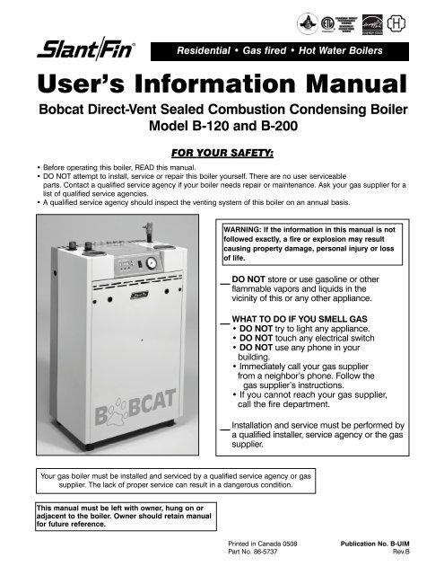
Residential • Gas fired • Hot Water <strong>Boiler</strong>s<br />
User’s Information Manual<br />
<strong>Bobcat</strong> Direct-Vent Sealed Combustion Condensing <strong>Boiler</strong><br />
Model B-120 and B-200<br />
FOR YOUR SAFETY:<br />
• Before operating this boiler, READ this manual.<br />
• DO NOT attempt to install, service or repair this boiler yourself. There are no user serviceable<br />
parts. Contact a qualified service agency if your boiler needs repair or maintenance. Ask your gas supplier for a<br />
list of qualified service agencies.<br />
• A qualified service agency should inspect the venting system of this boiler on an annual basis.<br />
WARNING: If the information in this manual is not<br />
followed exactly, a fire or explosion may result<br />
causing property damage, personal injury or loss<br />
of life.<br />
__ DO NOT store or use gasoline or other<br />
flammable vapors and liquids in the<br />
vicinity of this or any other appliance.<br />
__ WHAT TO DO IF YOU SMELL GAS<br />
• DO NOT try to light any appliance.<br />
• DO NOT touch any electrical switch<br />
• DO NOT use any phone in your<br />
building.<br />
• Immediately call your gas supplier<br />
from a neighbor’s phone. Follow the<br />
gas supplier’s instructions.<br />
• If you cannot reach your gas supplier,<br />
call the fire department.<br />
Your gas boiler must be installed and serviced by a qualified service agency or gas<br />
supplier. The lack of proper service can result in a dangerous condition.<br />
This manual must be left with owner, hung on or<br />
adjacent to the boiler. Owner should retain manual<br />
for future reference.<br />
__ Installation and service must be performed by<br />
a qualified installer, service agency or the gas<br />
supplier.<br />
Printed in Canada 0508 Publication No. B-UIM<br />
Part No. 86-5737 Rev.B
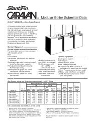
<strong>Bobcat</strong> Model B-120 and B-200 2<br />
WATER OUTLET<br />
WATER INLET<br />
PRESSURE<br />
RELIEF<br />
VALVE<br />
WATER<br />
HIGH<br />
LIMIT<br />
Figure 1. Location and identification of parts.<br />
SPARK<br />
ELECTRODES<br />
(IGNITOR)D<br />
WATER<br />
OUTLET<br />
SENSOR<br />
WATER<br />
INLET<br />
SENSOR<br />
FLUE<br />
SENSOR<br />
FLUE<br />
COLLECTOR<br />
BOILER<br />
DRAIN<br />
VALVE<br />
VENT<br />
MODE<br />
DISPLAY<br />
WELCOME TO OUR VALUED CUSTOMER<br />
You are now the owner of a <strong>Slant</strong>/<strong>Fin</strong> <strong>Bobcat</strong> series gas-fired<br />
boiler, another quality heating product designed and manufactured<br />
by an industry leader, to provide your family with<br />
many years of reliable comfort and trouble-free performance.<br />
The care and maintenance of your new boiler is important to<br />
prevent a hazardous condition which might result form lack<br />
of proper servicing. Therefore, you should perform regular<br />
“owner” inspections as described in this manual (and report<br />
any concerns to a qualified service technician) as well as<br />
have your boiler serviced by a qualified service technician at<br />
least once a year, preferably before the beginning of each<br />
heating season.<br />
LIGHTING INSTRUCTIONS<br />
Locate, read and then follow the procedures on the lighting<br />
instructions label attached to the boiler. For reference, we<br />
have reproduced those instructions in this manual.<br />
TEMPERATURE<br />
DISPLAY<br />
POWER<br />
SWITCH<br />
PRESSURE<br />
GAUGE<br />
GAS SUPPLY<br />
VALVE<br />
AIR<br />
INTAKE<br />
WINDOW<br />
(SIGHT GLASS)<br />
HEAT<br />
EXCHANGER<br />
CONDENSATE<br />
DRAIN<br />
CONDENSATE<br />
TRAP<br />
DO NOT use this boiler if any part has been<br />
underwater. Immediately call a qualified service<br />
technician to inspect the boiler and to replace<br />
any part of the control system and any gas<br />
control which has been underwater.<br />
WARNING<br />
Should overheating occur or the gas supply fail<br />
to shut off, DO NOT turn off or disconnect the<br />
electric supply to the circulator pump. Instead,<br />
shut off the gas supply at a location EXTERNAL<br />
to the appliance.<br />
WARNING<br />
SLANT/FIN DOES NOT PERMIT THE USE OF<br />
VENT DAMPERS ON BOBCAT B-120 or B-200<br />
SERIES BOILERS. OTHER DAMPERS OR<br />
DEVICES WITH SIMILAR PURPOSE ARE NOT<br />
PERMITTED.<br />
Keep the boiler area clean and free of all materials that can burn.<br />
NEVER close or reduce openings that supply air for the boiler fire and for ventilation.
3<br />
INSPECTION<br />
Your boiler and heating system will last an indefinitely long<br />
time at full efficiency, if it is inspected regularly and is kept<br />
in good repair and adjustment. You, the user, should make<br />
regular inspections, and report any problems to your<br />
service agency. At regular intervals, you should have that<br />
agency inspect the system and make repair adjustments<br />
as necessary. What you and the service agency should do<br />
is listed below. Contact your gas supplier for a list of qualified<br />
service and repair agencies.<br />
USER INSPECTION<br />
The user should make the following inspections at least<br />
once each month during the heating season and once<br />
just before cold weather starts. <strong>Bobcat</strong> B-120 and B-200<br />
boilers may be installed and vented either as direct-vent<br />
boiler, which all air for combustion is obtained directly<br />
from outside through the air intake piping or as nondirect-vent<br />
boiler, which all air for combustion is taken<br />
from inside the boiler room. Typical direct-vent installations<br />
are shown on Figures 2 and 3. Non-direct-vent<br />
installation is shown on Figures 4, 5 and 6.<br />
<strong>Bobcat</strong> Model B-120 and B-200<br />
1. VENTING AND AIR INTAKE SYSTEM REGULAR<br />
INSPECTION<br />
Inspect the system regularly for condensation, corrosion,<br />
sagging and/or physical damage. A qualified professional<br />
should service the boiler annually and include such an<br />
inspection at that time. The homeowner should look over<br />
the system monthly for damage, water stains, any signs of<br />
rust, other corrosions or separation of the vent and air<br />
intake piping (if direct-vent).<br />
Should an inspection turn up signs of condensation,<br />
corrosion, sagging or damage, the boiler should be shut<br />
down immediately and the condition should be corrected<br />
by a qualified professional.<br />
If the boiler is vented horizontally through the wall, the<br />
outside termination, louvers and screen should be checked<br />
for any debris blocking the opening and cleaned as<br />
required.<br />
Figure 2. Direct vent, sidewall venting illustration. Figure 3. Direct vent, venting and air intake<br />
through a roof.
<strong>Bobcat</strong> Model B-120 and B-200 4<br />
Figure 4. Non-direct vent, sidewall venting.
5<br />
Figure 5. Non-direct vent, venting through the roof.<br />
Figure 6. Non-direct vent, utilizing an existing chimney as a chase.<br />
<strong>Bobcat</strong> Model B-120 and B-200
<strong>Bobcat</strong> Model B-120 and B-200 6<br />
Figure 7. Condensate disposal system<br />
2. CONDENSATE REMOVAL SYSTEM<br />
The <strong>Bobcat</strong> B-120 and B-200 boilers are equipped with<br />
a built-in condensation drain and trap. The trap must be<br />
filled with water. DO NOT operate the boiler without filling<br />
the trap with water to prevent flue gas discharge<br />
into space. Periodic inspection should be made of this<br />
assembly for deterioration of the tubing and to insure<br />
that the trap is not plugged. If it is plugged or appears<br />
to have excessive sediment in it, it should be removed<br />
from the drain assembly, straightened out to clear the<br />
obstruction, reformed, filled with water and reinstalled<br />
as before. (See Figure 7).<br />
Leave the top of the condensate drain tee open, to act<br />
as a vacuum breaker. Do not allow any part of the<br />
condensate removal system to be exposed to freezing<br />
temperatures, or any other conditions that could cause<br />
blockage.<br />
If a neutralizing system is installed, the filter medium<br />
will require periodic changing, to ensure it’s effectiveness.<br />
Refer to the neutralizing unit’s manufacturers<br />
instructions, if available, or change the medium on an<br />
annual basis.<br />
3. PIPING INSPECTION<br />
Look at all water piping. There should be no leaks or<br />
signs of leaks at any pipe joints or around the boiler.<br />
4. SYSTEM WATER PRESSURE INSPECTION<br />
The boiler water pressure is indicated on the pressure<br />
gage (See Figure 1 for location). The boiler water outlet<br />
temperature is normally indicated on the temperature<br />
display (See Figure 1 for location and Figure 9 for digits<br />
illustration). For most installations, it should indicate<br />
about 12 to 15 psi pressure when temperature is about<br />
70 to 100F and from 15 psi to 25 psi when temperature<br />
is up to 195°F. FOR YOUR SYSTEM, there is one<br />
correct pressure for each temperature. ASK YOUR<br />
INSTALLER OR SERVICEPERSON TO EXPLAIN AND<br />
SHOW YOU. Learn what normal pressure to look for. If<br />
pressure increases from normal, the relief valve will<br />
open to relieve the pressure. Call your service organization<br />
if pressures are higher or lower than normal, and if<br />
the relief valve spills water. Repair or adjustment is<br />
needed.<br />
5. UNUSUAL NOISE<br />
Stand near the boiler and look and listen. As the burner<br />
start and shut off, there should be no unusual noise.<br />
6. BOILER ROOM AIR SUPPLY<br />
Ample boiler room fresh air is required for combustion<br />
(non-direct vent installation) and ventilation (direct-vent<br />
installation).<br />
Check air vents for continues positive supply of air as<br />
required. Air needs are greatest in cold weather if boiler<br />
installation is non-direct vent method. Air vents must be<br />
open and free of obstruction.<br />
Warning: The flow of combustion and ventilating air to the<br />
boiler should not be obstructed.<br />
Warning: If you find any problem during your inspection,<br />
call for service immediately.
7<br />
The combustion air supply must not be susceptible to<br />
contaminants, which may cause corrosion or other<br />
damage to the heat exchanger and components of the<br />
boiler, causing failure of these parts or unsafe<br />
operation.<br />
Below is a list of products which must be avoided from<br />
being stored or entering the boiler room or air supply<br />
area:<br />
PRODUCTS TO AVOID<br />
• Spray cans containing chloro/fluorocarbons<br />
• Permanent wave solutions<br />
• Chlorinated waxes/cleaners<br />
• Chlorine-based swimming pool chemicals<br />
• Calcium chloride used for thawing<br />
• Sodium chloride used for water softening<br />
• Refrigerant leaks<br />
• Paint or varnish removers<br />
• Hydrochloric acid/muriatic acid<br />
• Cements and glues<br />
• Antistatic fabric softeners used in clothes dryers<br />
• Chlorine-type bleaches, detergents and cleaning solvents<br />
found in household laundry rooms.<br />
• Adhesives used to fasten building products and other<br />
similar products.<br />
ANNUAL SERVICE AND GENERAL MAINTENANCE<br />
A trained and qualified service technician should<br />
perform inspection and general maintenance listed in<br />
Installation and Operating Instructions (Publication No.<br />
B-40) before each heating season and at regular<br />
intervals.<br />
WARNING: If you do not follow these instructions exactly, a<br />
fire or explosion may result causing property damage,<br />
personal injury or loss of life.<br />
SAFETY AND OPERATING INSTRUCTIONS<br />
Follow the lighting instructions in this manual. These<br />
instructions are also attached to the boiler.<br />
SAFETY INFORMATION<br />
For Your Safety Read Before Operating<br />
A. This appliance does not have a pilot. It is equipped<br />
with an ignition device which automatically lights the<br />
burner. Do not try to light the burner by hand.<br />
B. BEFORE OPERATING smell all around the appliance<br />
area for gas. Be sure to smell next to the floor because<br />
some gas is heavier than air and will settle on the floor.<br />
WHAT TO DO IF YOU SMELL GAS:<br />
• Do not try to light any appliance.<br />
• Do not touch any electric switch: do not use any<br />
phone in your building.<br />
• Immediately call your gas supplier from a neighbor’s<br />
phone. Follow the gas supplier’s instructions.<br />
• If you cannot reach your gas supplier, call the fire<br />
department.<br />
<strong>Bobcat</strong> Model B-120 and B-200<br />
C. Use only your hand to turn the gas supply shut off<br />
valve. Never use tools. If the supply shut off will not<br />
turn by hand, don’t try to repair it, call a qualified service<br />
technician. Force or attempted repair may result<br />
in a fire or explosion.<br />
D. DO NOT use this appliance if any part has been under<br />
water. Immediately call a qualified service technician to<br />
inspect the appliance and to replace any part of the<br />
control system and any gas control which has been<br />
under water.<br />
OPERATING INSTRUCTIONS<br />
1. STOP! Read the safety information above.<br />
2. Set the thermostat to lowest setting.<br />
3. Turn off all electric power to the appliance.<br />
4. This appliance is equipped with an ignition device<br />
which automatically lights the burner. Do not try to<br />
light the burner by hand.<br />
5. Open the gas supply shut off valve, by turning the<br />
handle to be parallel to the gas piping. (See Figure 8).<br />
6. Wait five (5) minutes (longer for propane) to clear out<br />
any gas, then smell for gas, including near the floor. If<br />
you then smell gas, STOP! Follow “B” in the safety<br />
information above on this page. If you don’t smell gas,<br />
go to next step.<br />
7. Turn on all electric power to the appliance.<br />
8. Set thermostat to desired setting.<br />
If the appliance will not operate, follow the instructions<br />
“To Turn Off Gas to Appliance” and call your service<br />
technician or gas supplier.<br />
To Turn Off Gas to Appliance<br />
1. Set thermostat to lowest setting.<br />
2. Turn off all electric power to the appliance if service<br />
is to be performed.<br />
3. Close the gas supply shut off valve, by turning the<br />
handle to be perpendicular to the gas piping.<br />
(See Figure 8).<br />
Figure 8.
<strong>Bobcat</strong> Model B-120 and B-200 8<br />
Removing Jacket Front Panel<br />
1. Turn black screws 1/4 turn to open position.<br />
2. Remove front panel.<br />
To replace the panel, reverse procedure.<br />
INTEGRATED BOILER CONTROL<br />
The integrated boiler control monitors the status of the<br />
room thermostat, high limit switch, low water cutoff (if<br />
installed), water inlet and outlet sensors, flue gas sensor<br />
and flame sensor. It controls the operation of the circulator,<br />
combustion blower, gas valve and spark ignitor. The<br />
boiler control also determines the sequence of operation<br />
and timing for pre and post purge periods, trial for ignition<br />
and lock out.<br />
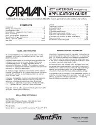
The control display board provides information on boiler<br />
operation on a mode and temperature display and can<br />
be viewed, programmed and reset with specific push buttons.<br />
Diagnostic information is also provided on the display,<br />
to help determine the cause of boiler failure. (See<br />
Figure 9).<br />
BOILER CONTROL AND DISPLAY FEATURES<br />
(See Figure 9)<br />
A. BOILER OPERATION STATUS: “Mode <strong>Display</strong>”<br />
shows status of boiler operation. (See Table 1).<br />
B. VIEW AND CHANGING TEMPERATURES: Setting<br />
boiler supply water temperature and water tank<br />
temperatures (See Table 2).<br />
Press “Select” button for viewing following different<br />
modes on “Mode <strong>Display</strong>”<br />
1. While “c” is blinking, boiler supply water<br />
temperature for space heating may be set to<br />
Figure 9. <strong>Display</strong> <strong>Board</strong><br />
desired temperature. The setting range is between<br />
90° to 185°F.<br />
2. While “d” is blinking, boiler supply water<br />
temperature for DHW may be set to desired<br />
temperature. The setting range is between 104° to<br />
185°F.<br />
3. While “t” is blinking, DHW tank temperature may<br />
be set to desired temperature (if tank is equipped<br />
with sensor). The setting range is between 104° to<br />
185°F.<br />
4. View actual boiler supply & return water<br />
temperature, domestic hot water tank temperature<br />
(if tank equipped with sensor), flue temperature<br />
and outside temperature (if outside sensor is used)<br />
on “Temperature <strong>Display</strong>” by selecting 1, 2, 3, 4 or<br />
5 on “Mode <strong>Display</strong>”.<br />
C. <strong>Display</strong> <strong>Board</strong> Pushbuttons:<br />
1. Reset - Used to clear a Lockout Error<br />
(indicated with an “A” in the “Mode <strong>Display</strong>”)<br />
2. Select - Used to scroll through the modes in the<br />
“View and Changing Temperatures” and<br />
“Viewing and Changing System Setting” menus.<br />
3. Enter - Used to store values that are changed in<br />
the “View and Changing Temperatures” and<br />
“Viewing and Changing System Setting” menus.<br />
4. Up - Used to increase values in the “View and<br />
Changing Temperatures” and “Viewing and<br />
Changing System Setting” menus.<br />
5. Down - Used to decrease values in the “View and<br />
Changing Temperatures” and “Viewing and<br />
Changing System Setting” menus.
9<br />
Table 1<br />
Note:<br />
Mode<br />
<strong>Display</strong><br />
<strong>Bobcat</strong> <strong>Boiler</strong> <strong>Display</strong> <strong>Board</strong><br />
“<strong>Boiler</strong> Operation Status”<br />
<strong>Bobcat</strong> Model B-120 and B-200<br />
Description & Temperature <strong>Display</strong><br />
<strong>Boiler</strong> is on stand-by mode.<br />
Temperature display shows supply water Temp.<br />
Space heating mode.<br />
Temperature display shows supply water Temp.<br />
Domestic hot water mode.<br />
Temperature display shows supply waterTemp.<br />
Frost protection mode.**<br />
Temperature display shows supply water Temp.<br />
Lockout (Alarm) condition.<br />
Temperature <strong>Display</strong> indicates the lockout code<br />
Reset button must be pressed to resume normal operation.<br />
Error Condition. *<br />
Temperature display indicates the error code.<br />
Warning Condition. ***<br />
Temperature display indicates the error code.<br />
Blinking dot on “Mode <strong>Display</strong>” indicates active heating control, burner off. Steady dot<br />
indicates burner is on.<br />
*: Error must be corrected to resume boiler operation. Pressing the “Reset” button is not<br />
required.<br />
**: The boiler circulator is energized, when boiler water temperature drops below 50°F.<br />
***: Error must be corrected to resume DHW operation. Space heating not affected.<br />
Pressing the “Reset” button is not required.
<strong>Bobcat</strong> Model B-120 and B-200 10<br />
Table 2<br />
Table 2: Viewing and Changing Temperatures<br />
Mode<br />
<strong>Display</strong><br />
Press “Select” button for viewing different modes on “Mode <strong>Display</strong>”<br />
Blinking<br />
Blinking<br />
Blinking<br />
Description & Temperature <strong>Display</strong><br />
Space heating supply water temperature could be<br />
changed by pressing “Up/Down” button. Settable from<br />
90°F to 185°F (steps of 1 F). The default valve is 176°F<br />
Press “Enter” button to store. (see note 1)<br />
Domestic hot water supply temperature could be changed<br />
by pressing “Up/Down” button. Settable from<br />
104°F to 185°F (steps of 1 F). The default valve is 176° F<br />
Press “Enter” button to store.<br />
(see note 2)<br />
Domestic hot water tank temperature could be changed<br />
by pressing “Up/Down” button. Settable from 104°F to<br />
160°F (steps of 1 F). The default valve is 140°F.<br />
Press “Enter” button to store. (see note 3)<br />
Temperature display shows actual<br />
supply water temperature.<br />
Temperature display shows actual<br />
return water temperature.<br />
Temperature display shows actual DHW tank temperature.<br />
(if the water tank is equipped with sensor)<br />
Temperature display shows actual flue gas temperature.<br />
Temperature display shows actual outside temperature.<br />
(boilers with outdoor sensor)<br />
Notes:<br />
1. For space heating mode “0” (boilers not utilizing outdoor sensor)<br />
2. For DHW mode “2” (storage tank with Aquastat)<br />
3. For DHW mode “1” (storage tank with sensor)
11<br />
DIAGNOSTIC ERROR CODES<br />
WARNING:<br />
If an operational problem has occurred, the boiler will<br />
shut off and show an “A”, “E” or “H” in the mode display,<br />
along with an error code in the temperature display.<br />
Do not attempt performing any service under these<br />
conditions, but do note the mode and temperature display<br />
indication, in case the problem clears itself. An “A”<br />
indication error can be cleared by pressing the reset<br />
button once, which will allow re-try of operation. Do not<br />
repeatedly press the reset button in this case, or if an<br />
“E” or “H” indication error is displayed. Call a trained,<br />
experienced service technician to troubleshoot and correct<br />
the problem. The <strong>Bobcat</strong> Installation and Operating<br />
Instructions, publication B-40 contain a full troubleshooting<br />
section for this. Turn off all electric power<br />
ot the boiler before service.<br />
A. LOCKOUT ERRORS:<br />
Indicated by an “A” in the mode display. The reset<br />
button must be pressed to clear the error and retry<br />
operation. The temperature display shows the error<br />
code.<br />
ERROR<br />
INDICATION<br />
CODE<br />
Ignition Failure - 3 unsuccessful ignition<br />
01<br />
attempts in a row<br />
Flame Failure - 3 losses of flame signal<br />
02<br />
during one demand<br />
03 Water High Limit Open<br />
04, 05, 09,<br />
10, 12, 13,<br />
14, 15, 16,<br />
18, 32<br />
Control Failure<br />
19, 20 Flame Detected at Wrong Time<br />
33 Fan Failure - RPM Error<br />
B. BLOCKING ERRORS:<br />
Indicated by an “E” in the mode display. Operation<br />
is automatically restored, once the condition returns<br />
to normal or is fixed. The temperature display<br />
shows the error code. Pressing the “Reset” button<br />
is not required.<br />
ERROR<br />
CODE<br />
<strong>Bobcat</strong> Model B-120 and B-200<br />
INDICATION<br />
01 Water Outlet Sensor Open<br />
02 Water Inlet Sensor Open<br />
03 Flue Gas Sensor Open<br />
11 Water Outlet Sensor Shorted<br />
12 Water Inlet Sensor Shorted<br />
13 Flue Gas Sensor Shorted<br />
19, 42,<br />
45, 46,<br />
47, 48<br />
Control Failure<br />
20 Flame Detected at Wrong Time<br />
21 Polarity Error<br />
22 Frequency Error<br />
24 Earth Connection Faulty<br />
30 Excess Flue Temperature<br />
31 Low Water Cutoff Error<br />
32 Excess Water Inlet Temperature<br />
51 Reset Button Error<br />
52 <strong>Boiler</strong> Model Selection Error<br />
C. WARNING ERRORS:<br />
Indicated by an “H” in the mode display. Operation<br />
of the space heating mode is not affected, and the<br />
warning is displayed intermittently. Operation of the<br />
DHW mode is automatically restored, once the<br />
condition is fixed. The temperature display shows<br />
the error code. Pressing the “Reset” button is<br />
not required.<br />
ERROR<br />
CODE<br />
INDICATION<br />
04 Domestic Hot Water Tank Sensor Open<br />
14 Domestic Hot Water Tank Sensor Shorted
©<strong>Slant</strong>/<strong>Fin</strong> Corp. 2008<br />
SLANT/FIN LTD/LTEE, 6450 Northam Drive, Mississauga, Ontario L4V 1H9<br />
• Phone: (905) 677-8400 / FAX: (905) 677-1829 / Order Desk Fax: (905) 677-9015<br />
www.slantfin.ca / E-mail: orderdesk@slantfin.ca / info@slantfin.ca