Simulation Homework 2, due Friday week 4 - Milwaukee School of ...
Simulation Homework 2, due Friday week 4 - Milwaukee School of ...
Simulation Homework 2, due Friday week 4 - Milwaukee School of ...

You also want an ePaper? Increase the reach of your titles
YUMPU automatically turns print PDFs into web optimized ePapers that Google loves.
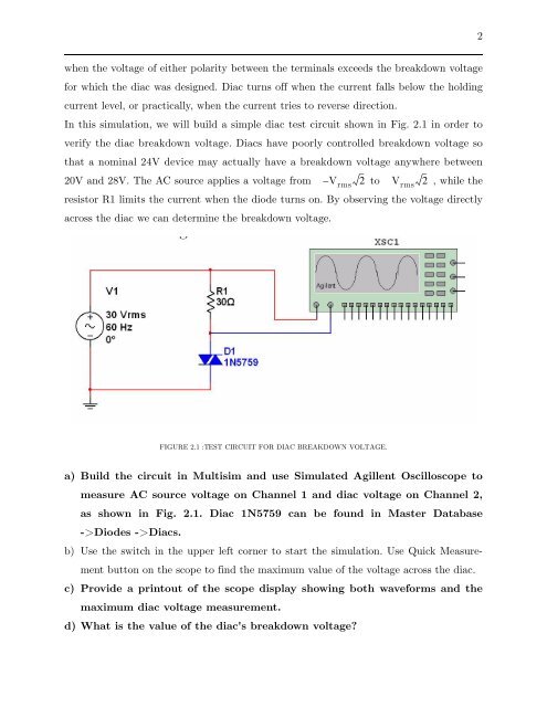
2when the voltage <strong>of</strong> either polarity between the terminals exceeds the breakdown voltagefor which the diac was designed. Diac turns <strong>of</strong>f when the current falls below the holdingcurrent level, or practically, when the current tries to reverse direction.In this simulation, we will build a simple diac test circuit shown in Fig. 2.1 in order toverify the diac breakdown voltage. Diacs have poorly controlled breakdown voltage sothat a nominal 24V device may actually have a breakdown voltage anywhere between20V and 28V. The AC source applies a voltage from – V rms2 to V rms2 , while theresistor R1 limits the current when the diode turns on. By observing the voltage directlyacross the diac we can determine the breakdown voltage.FIGURE 2.1 :TEST CIRCUIT FOR DIAC BREAKDOWN VOLTAGE.a) Build the circuit in Multisim and use Simulated Agillent Oscilloscope tomeasure AC source voltage on Channel 1 and diac voltage on Channel 2,as shown in Fig. 2.1. Diac 1N5759 can be found in Master Database->Diodes ->Diacs.b) Use the switch in the upper left corner to start the simulation. Use Quick Measurementbutton on the scope to find the maximum value <strong>of</strong> the voltage across the diac.c) Provide a printout <strong>of</strong> the scope display showing both waveforms and themaximum diac voltage measurement.d) What is the value <strong>of</strong> the diac's breakdown voltage?