Simulation Homework 2, due Friday week 4 - Milwaukee School of ...
Simulation Homework 2, due Friday week 4 - Milwaukee School of ...
Simulation Homework 2, due Friday week 4 - Milwaukee School of ...

You also want an ePaper? Increase the reach of your titles
YUMPU automatically turns print PDFs into web optimized ePapers that Google loves.
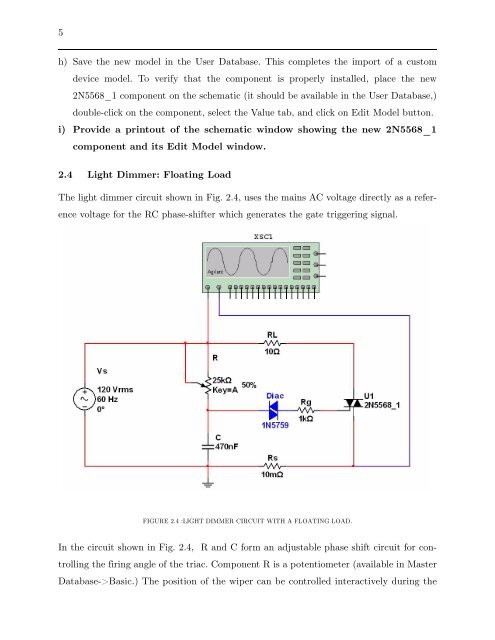
5h) Save the new model in the User Database. This completes the import <strong>of</strong> a customdevice model. To verify that the component is properly installed, place the new2N5568_1 component on the schematic (it should be available in the User Database,)double-click on the component, select the Value tab, and click on Edit Model button.i) Provide a printout <strong>of</strong> the schematic window showing the new 2N5568_1component and its Edit Model window.2.4 Light Dimmer: Floating LoadThe light dimmer circuit shown in Fig. 2.4, uses the mains AC voltage directly as a referencevoltage for the RC phase-shifter which generates the gate triggering signal.FIGURE 2.4 :LIGHT DIMMER CIRCUIT WITH A FLOATING LOAD.In the circuit shown in Fig. 2.4, R and C form an adjustable phase shift circuit for controllingthe firing angle <strong>of</strong> the triac. Component R is a potentiometer (available in MasterDatabase->Basic.) The position <strong>of</strong> the wiper can be controlled interactively during the