ADT FSC Quick Reference Card - Edwards Signaling
ADT FSC Quick Reference Card - Edwards Signaling
ADT FSC Quick Reference Card - Edwards Signaling
- No tags were found...

You also want an ePaper? Increase the reach of your titles
YUMPU automatically turns print PDFs into web optimized ePapers that Google loves.
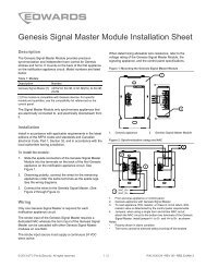
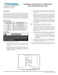
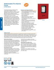
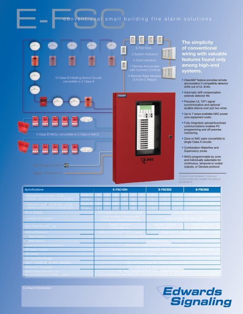
E-<strong>FSC</strong>c o n v e n t i o n a l s m a l l b u i l d i n g f i r e a l a r m s o l u t i o n s4 Class B NACs, convertible to 2 Class A NACsDACT/Dialer (F-DACT)Relays: Three Form C10 Class B Initiating Device Circuits,convertible to 5 Class AE-<strong>FSC</strong>1004...2 System Indicators4 Zone Indicators1 Remote Annunciatorwith Common Controls4 Remote Relay Modules(5 Form C Relays)The simplicityof conventionalwiring with valuablefeatures found onlyamong high-endsystems.• CleanMe ® feature provides remoteannunciation if compatible detectordrifts out of UL limits• Automatic drift compensationextends detector life• Precision UL 1971 signalsynchronization and optionalaudible silence over just two wires• Up to 7 amps available NAC powercuts equipment costs• Fully integrated upload/downloadcommunications enables PCprogramming and off-premisemonitoring• Zone or NAC pairs convertible tosingle Class A circuits• Combination Waterflow andSupervisory zones• NACs programmable by zoneand individually selectable forcontinuous, temporal or codedoutputs, or Genesis protocol10-zone model illustrated. 5-zone and3-zone models also available.See table forspecifications.Specifications E-<strong>FSC</strong>1004 E-<strong>FSC</strong>502 E-<strong>FSC</strong>302Contact Information:
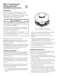
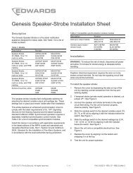
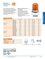
<strong>Quick</strong> <strong>Reference</strong>Consult relevant literature for full listing of available models and options.Control PanelsConventional Fire Alarm ControlE-<strong>FSC</strong>1004RD Panel with dialer, 10 Class BIDCs and 4 Class B NACsConventional Fire Alarm ControlE-<strong>FSC</strong>502RD Panel with dialer, 5 Class B IDCsand 2 Class B NACsConventional Fire Alarm ControlE-<strong>FSC</strong>302RD Panel with dialer, 3 Class B IDCsand 2 Class B NACsSemi-Flush Mount Trim Kit forF-TRIM10RE-<strong>FSC</strong>1004RSemi-Flush Mount Trim Kit forF-TRIM35RE-<strong>FSC</strong>502R and E-<strong>FSC</strong>302RBC-1R Battery Cabinet, red12V6A5 7.2 Ah Batteries12V10A 11.0 Ah Batteries12V17A 18 Ah BatteriesOption <strong>Card</strong>sExpander X-Former, 120 Vac,F-XTR120E-<strong>FSC</strong>1004RD onlyCity Tie Module (Requires 4” sq.CTMbox or 2-gang)Reverse Polarity Module, RequiresRPMMFC-A or other listed FA enclosureRemote Relay Module – 5 Form Crelays, Config. IDCs 1-5, or 6-10,FSRRM24 or common system indicators,Requires MFC-A or other listed FAenclosureRemote AnnunciationRemote System Indicator – Power,FSRSI Alarm, Super., Trouble, and GrndLEDs (Single Gang trim included)Remote Zone Indicator – 5 RedFSRZI-A LEDs for 5 IDCs(Single Gang trim included)Remote Zone Indicator – 5 Bi-ColorFSRZI-SA LEDs (Red/Yellow) for 5 IDCs(Single Gang trim included)FSAT-2 Ann. Trim Plate, 2-GangFSAT3 Ann. Trim Plate, 3-GangRemote Annunciator 10-Zone Bi-Color LEDs (Red/Yellow) w/ SystemFSRA10Indicators for E-<strong>FSC</strong>1004RD(4” sq. box mnt.)Remote Annunciator10-Zone Bi-Color LEDs (Red/FSRA10C Yellow) w/ System Indicators &Controls for E-<strong>FSC</strong>1004RD(4” sq. box mnt.)Graphic Drive/Interface providingFSUIMSystem Indicators and ControlsPower SuppliesEBPS6A 6.5 Amp Booster Power SupplyEBPS6A 6.5 Amp Booster Power SupplyEBPS10A 10 Amp Booster Power Supply12V6A5 7.2 Ah Batteries12V10A 11.0 Ah BatteriesBC-1R - Red Battery Cabinet2-Wire Detectors and BasesPhotoelectric Smoke Detector, Base511CincludedPhotoelectric Smoke with CleanME521BFeature, Base includedConventional photoelectric smokeTS7-2 detector, 6” 3-terminal base,12/24VDC. 3-terminal base 701U.Conventional photoelectric smokeTS7-2T detector, FS & RoR heat, remotealarm/trouble LED., 12/24VDC.Heat Detectors281B-PL 135* Fixed / RoR Heat Detector282B-PL 194* Fixed / RoR Heat Detector135* Fixed / RoR Moisture Proof302-AW-135Heat Detector194* Fixed / RoR Moisture Proof302-AW-194Heat Detector2-Wire Duct DetectorsSD-2W Conventional SuperDuct DetectorSD-Txx Sampling Tubes for SuperDuctSD-TRK4 Remote Test Stations for SuperDuctManual Stations278B-1110Double Action Pull Station, Term.,Tool Reset, Lexan278B-1120Double Action Pull Station, Term.,Key Reset, Lexan276B-RSB Surface Mount Box, RedMPSR1-S45W-GEWeatherproof Manual Station,c/w backboxStrobes, HornsEG1RF-VMWall Strobe, 15-110 cd, Marked“Fire”, 24VDC, redWall Horn/Strobe, 15-110 cd,EG1RF-HDVMMarked “Fire”, 24VDC, redEG1RF-HDWall Horn, Temporal, High/Low dB,Marked “Fire”, 24VDC, RedEG1RTGenesis Trim Plate (for 2-gang or4” sq. boxes), redEGCF-VMCeiling Multi-cd Strobe, 15-95 cd,Marked “Fire”, redEGCF-VMHCeiling Multi-cd Strobe, 95-177 cd,Marked “Fire”, redEGCF-HDVMCeiling Multi-cd Horn-Strobe, 75-95 cd, Marked “Fire”, redCeiling Multi-cd Horn-Strobe,EGCF-HDVMH95-177 cd, Marked “Fire”, redCS405-8A-T Weatherproof Strobe, 110 cd2452THS-110-RWeatherproof Horn/Strobe, 110 cd449 Weatherproof Box for CS405 strobes2459WPB-R Weatherproof Surface Box, redDoorholders1501-AQN5 Single Door, Floor Mounted1502-AQN5 Double Door, Floor Mounted1504-AQN5 Long Catch Plate, Flush Wall Mnt.1505-AQN5 Short Catch Plate, Flush Wall Mnt.1508-AQN5 Surface, Wall MountedRelaysMR101/CMR201/CPAM1Single SPDT relay. Contact Rating10 Amps @ 115Vac and Coil Power24 Vac, 24Vdc, 115Vac or 230Vac.Single DPDT relay. Contact Rating10 Amps @ 115Vac and Coil Power24 Vac, 24Vdc, 115Vac or 230Vac.Encapsulated SPDT relay. ContactRating 10 Amps @ 115Vac and CoilPower 24 Vac, 24Vdc, or 115Vac.For complete productspecifications and orderinginformation, see Data SheetS85005-0126 – E-<strong>FSC</strong>Conventional Fire AlarmControl Panels.Booster NAC Class B (Style Power Y) wiring SupplyConsult Connect relevant a single literature NAC circuit for application to one NAC details. output. Terminate thecircuit with a 15 kΩ EOL resistor.NAC Class BwiringNAC1NAC2NAC3++++NAC4200 mA AUXContinuousTB5TB1INSense 1 COMOUTINSense 2 COMOUTNOTrouble COMNCTB2Notification appliance circuit (NAC)UL listedEOL 15 kΩNotification appliance circuit (NAC)UL listedEOL 15 kΩ++EOL[3]Input or signaling circuitTo next signalingdevice, booster, or NACend-of-line resistorSpecifications EBPS6A - 6.5 amp Booster EBPS10A - 10 amp BoosterAC Line 120VAC 50/60Hz 390 watts 120VAC 50/60Hz 580 wattsVoltage NAC Class A (Style Z) wiringNAC Ratings24Vdc nominal24Vdc nominalConnect one NAC 6.5A circuit max to total one all NAC NACsoutput, either 10A NAC1 max total or all NAC3. NACsTrouble Terminate Relaythe circuit at the NAC2 or 2 NAC4 Amps @ terminal 30Vdc screw,Auxiliary respectively.OutputsFour individually configurable outputs can replace NACs 1, 2, 3 or4 as auxiliary outputs.200 mA dedicated auxiliary for use with E-NAC module.TB1Input Current6mA @ 24Vdc (from an existing Notification NAC)Current NAC170mA (Booster Internal appliance Supervisory)Maximum10 Amp Hours (2 of 12V10A) circuit in cabinet (NAC)NAC2Battery Size up to 24 Amp hours with external battery cabinet (p/n BC-1R)Paige Wire Twisted nonshielded FPLP #14 AWG – 4719A Notification or #12 AWG – 4725ANAC3(THHN or TFN in conduit can appliance be used on NAC)circuit (NAC)Environmental NAC4Temperature 32° to 120°F (0° to 49°C),Humidity 0 to 93% non condensing @ 32°CNAC 200 Wiring mA AUXChapter 2: Installation(4) Class B or (2) Class AContinuousInput or signaling circuitOutput SignalContinuous, 3-3-3 temporal,INRatesor follow installed panel’s NAC.Installing Sense 1 COM remote modulesOUTTo next signaling device, NACFigure 6 shows the maximum IN number of devices that you can installon the Sense remote 2module communication bus. booster, Refer to the or installation NAC returningCOMsheet provided with the remote module forOUTmounting existing and control wiring panelAnnunciator instructions. Wiring diagrams are also provided Busin Appendix C.NOConsult TroubleEOLFigure 6: Remote relevant COM module literature bus block diagram for application details.[3]NCPeripheral group 1 AC power failTB2monitoringFACPDataPower++++TB5FSRSI++FSRZI-AorFSZRI-SAZones1 to 5FSRZI-AorFSZRI-SAZones6 to 10Remote Booster Power Supply Technical <strong>Reference</strong> ManualNotesFSRSIorFSUIMFSRZI-AorFSZRI-SAZones1 to 5FSRZI-AorFSZRI-SAZones6 to 10NACAC power failmonitoringFSRRM24 FSRRM24 FSRRM24 FSRRM24CommonrelayPeripheral group 2Zones1 to 5Zones6 to 10MatrixFSRRM24 FSRRM24 FSRRM24 FSRRM24CommonrelayZones1 to 5Zones6 to 10• Important Install only points one FSRRM24 configured for common relay operation (jumper installed• on You JP5) can per only peripheral install one FSRRM24 group. configured for common relay• Install operation zone (jumper indicator installed modules on JP5) per only peripheral for zones group 6 to 10 on ten-zone control panels.• You can only install zone indicator modules for zones 6 to 10 on• For ten-zone control panels, install an F-series remote annunciator in place of theten-zone control panelsFSRSI and the two zone indicator modules (FSRZI-A or FSRZI-SA).• For ten-zone control panels, you can install an F-series remote• If annunciator the remote in modules place of the require FSRSI and more the two power zone than indicator the control panel can provide, usea modules power-limited (FSRZI-A and or FSRZI-SA) regulated 24 VDC auxiliary/booster power supply that is UL/• ULC If the Listed remote for modules fire protective require more signaling power than systems the control to power all or some of the remotemodules. panel can provide, use a power-limited and regulated 24 VDCauxiliary/booster power supply that is UL/ULC Listed for fireprotective signaling systems to power all or some of the remotemodulesMatrixNAC wiri1. A tropowethe epanecausthatthe nmonicontapowebelowIn anboosallowmovedevicexistNAC2. Refercontrdocudetai[3] The Apaneannubut dprempredperioappliS85000-0373