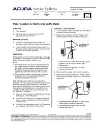
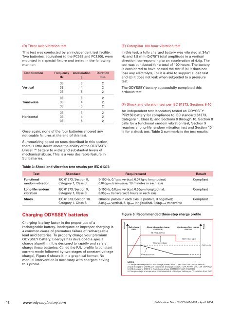
(D) Three axis vibration testThis test was conducted by an independent test facility.Two batteries, equivalent to the PC925 and PC1200, weremounted in a special fixture and tested in the followingmanner:Test direction Frequency Acceleration DurationHz g min.33 3 2Vertical 33 4 233 6 233 3 2Transverse 33 4 233 6 233 3 2Horizontal 33 4 233 6 2Once again, none of the four batteries showed anynoticeable failures at the end of this test.Summarizing based on tests described in this section,there is little doubt about the ability of the ODYSSEYDrycell battery to withstand substantial levels ofmechanical abuse. This is a very desirable feature inSLI batteries.(E) Caterpillar 100-hour vibration testIn this test, a fully charged battery was vibrated at 34±1Hz and 1.9 mm (0.075”) total amplitude in a verticaldirection, corresponding to an acceleration of 4.4g. Thetest was conducted for a total of 100 hours. The batteryis considered to have passed the test if (a) it does notlose any electrolyte, (b) it is able to support a load testand (c) it does not leak when subjected to a pressuretest.The ODYSSEY battery successfully completed thisarduous test.(F) Shock and vibration test per IEC 61373, Sections 8-10An independent test laboratory tested an ODYSSEYPC2150 battery for compliance to IEC standard 61373,Category 1, Class B, and Sections 8 through 10. Section 8calls for a functional random vibration test, Section 9requires a long-life random vibration test and Section 10is for a shock test. Table 3 summarizes the test results.Table 3: Shock and vibration test results per IEC 61373Test Standard Requirement ResultFunctional IEC 61373, Section 8, 5-150Hz, 0.1grms vertical, 0.071grms longitudinal, Compliantrandom vibration Category 1, Class B 0.046grms transverse; 10 minutes in each axisLong-life random IEC 61373, Section 9, 5-150Hz, 0.8grms vertical, 0.56grms longitudinal, Compliantvibration Category 1, Class B 0.36grms transverse; 5 hours in each axisShock IEC 61373, Section 10, 30msec. pulses in each axis (3 positive, 3 negative); CompliantCategory 1, Class B 3.06gpeak vertical, 5.1gpeak longitudinal, 3.06gpeak transverseCharging ODYSSEY batteriesFigure 6: Recommended three-step charge profileCharging is a key factor in the proper use of arechargeable battery. Inadequate or improper charging isa common cause of premature failure of rechargeablelead acid batteries. To properly charge your premiumODYSSEY battery, EnerSys has developed a specialcharge algorithm. It is designed to rapidly and safelycharge these batteries. Called the IUU profile (a constantcurrent mode followed by two stages of constant voltagecharge), Figure 6 shows it in a graphical format. Nomanual intervention is necessary with chargers havingthis profile.VoltageBulk charge(RED)8-hour absorption charge(ORANGE)14.7V (2.45 Vpc)Charge currentCharge voltageContinuous float charge(GREEN)13.6V (2.27 Vpc)NOTES:1. Charger LED stays RED in bulk charge phase (DO NOT TAKE BATTERY OFF CHARGE)2. LED changes to ORANGE in absorption charge phase (BATTERY AT 80% STATE OF CHARGE)3. LED changes to GREEN in float charge phase (BATTERY FULLY CHARGED)4. Charge voltage is temperature compensated at ±24mV per battery per ºC variation from 25ºCAmps0.4C10 min12 www.odysseyfactory.comPublication No: US-ODY-AM-001 - April 2006
If the charger has a timer, then it can switch fromabsorption mode to float mode when the current dropsto 0.001C10 amps. If the current fails to drop to 0.001C10amps, then the timer will force the transition to a floatcharge after no more than 8 hours. As an example, for aPC1200 battery, the threshold current should be 44mA.Another option is to let the battery stay in the absorptionphase (14.7V or 2.45 VPC) for a fixed time, such as 6-8hours, then switch to the continuous float charge. Table 3shows three charger design variations, all based on thebasic three-step profile shown in Figure 6.Table 4: Three-step charger design optionsCharge Phase & FeatureBulk Absorption Timer Trigger Floatcharge charge current, A chargeDesign 1 Yes Yes Yes 0.001C10 YesDesign 2 Yes Yes Yes No trigger YesDesign 3 Yes Yes No 0.10C10 YesIn Design 1, the charger has a timer and a currentthreshold that triggers the switch from absorption chargeto float charge. Because the charger has a timer override,the charge current is set at a low value. If the chargecurrent does not drop to 0.001C10 amps within 8 hours onabsorption charge, then the timer will force the chargerto switch to a temperature-compensated float charge.The charger does not have a current trigger in Design 2.Rather, the timer forces the charger to stay in theabsorption phase for a fixed time (8 hours) beforeallowing it to switch down to a temperaturecompensatedfloat charge.Because the charger in Design 3 does not have a timer,the threshold current to trigger the switch from theabsorption phase to the temperature-compensated floatcharge phase is kept relatively high. Note that in thisdesign the battery will not be fully charged when thecharger switches to the float charge phase. A minimumof 16-24 hours on float will be required to complete thecharge.Table 5 shows the minimum charge currents for thefull range of ODYSSEY batteries. When using a chargerwith the IUU profile, we suggest the following ratingsfor your ODYSSEY battery. Note the charger current inthe bulk charge mode must be 0.4C10 or more. A list ofchargers approved by EnerSys for use withODYSSEY batteries is available athttp://www.odysseyfactory.com/odycharg_c.htm.Table 5: <strong>Battery</strong> size and minimum three-step chargercurrentChargerrating, amps6A10A15A25A25A40A50ARecommended ODYSSEY modelPC310 / PC535 / PC545 / PC625 / PC680PC925 or smaller batteryPC1200 or smaller batteryPC1500 or smaller batteryPC1700 or smaller batteryPC2150 or smaller batteryPC2250 or smaller batterySmall, portable automotive and powersport chargersmay also be used to charge your ODYSSEY battery.These chargers are generally designed to bring adischarged battery to a state of charge (SOC) that is highenough to crank an engine. Once the engine issuccessfully cranked its alternator should fully charge thebattery. It is important to keep in mind the designlimitations of these small chargers when using them.Another class of chargers is designed specifically tomaintain a battery in a high SOC. These chargers,normally in the 3 /4 amp to 1 1 /2 amp range, are not bigenough to charge a deeply discharged ODYSSEY battery.They must only be used either to continuouslycompensate for parasitic losses or to maintain a tricklecharge on a stored battery, as long as the correctvoltages are applied. It is very important, therefore, toensure that the ODYSSEY battery is fully charged beforethis type of charger is connected to it.(A) Selecting the right charger for your batteryQualifying portable automotive and powersport chargersfor your ODYSSEY battery is a simple two-step process.Step 1 Charger output voltageDetermining the charger output voltage is the mostimportant step in the charger qualification process.If the voltage output from the charger is less than 14.2Vor more than 15V for a 12V battery, then do not use thecharger. For 24V battery systems, the charger outputvoltage should be between 28.4V and 30V. If the chargeroutput voltage falls within these voltage limits when thebattery approaches a fully charged state, proceed toStep 2, otherwise pick another charger.Step 2 Charger type - automatic or manualThe two broad types of small, portable chargersavailable today are classified as either automatic ormanual. Automatic chargers can be further classified asthose that charge the battery up to a certain voltage andthen shut off and those that charge the battery up to acertain voltage and then switch to a lower float (trickle)voltage.www.odysseyfactory.comPublication No: US-ODY-AM-001 - April 200613


![Keyless Remote Manual [pdf] - Dali Racing](https://img.yumpu.com/49994721/1/190x245/keyless-remote-manual-pdf-dali-racing.jpg?quality=85)