M2 Antenna Systems, Inc. Model No: 2MCP14
M2 Antenna Systems, Inc. Model No: 2MCP14
M2 Antenna Systems, Inc. Model No: 2MCP14
- No tags were found...

Create successful ePaper yourself
Turn your PDF publications into a flip-book with our unique Google optimized e-Paper software.
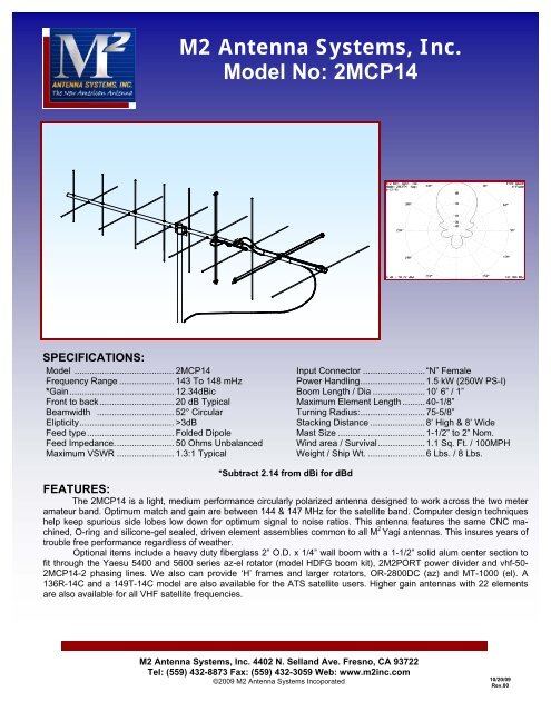
<strong>M2</strong> <strong>Antenna</strong> <strong>Systems</strong>, <strong>Inc</strong>.<strong>Model</strong> <strong>No</strong>: <strong>2MCP14</strong>SPECIFICATIONS:<strong>Model</strong> ........................................ <strong>2MCP14</strong>Frequency Range ...................... 143 To 148 mHz*Gain.......................................... 12.34dBicFront to back.............................. 20 dB TypicalBeamwidth ............................... 52° CircularElipticity...................................... >3dBFeed type................................... Folded DipoleFeed Impedance........................ 50 Ohms UnbalancedMaximum VSWR ....................... 1.3:1 TypicalInput Connector .........................“N” FemalePower Handling..........................1.5 kW (250W PS-I)Boom Length / Dia .....................10’ 6” / 1”Maximum Element Length .........40-1/8”Turning Radius:..........................75-5/8”Stacking Distance ......................8’ High & 8’ WideMast Size ...................................1-1/2” to 2” <strong>No</strong>m.Wind area / Survival...................1.1 Sq. Ft. / 100MPHWeight / Ship Wt. .......................6 Lbs. / 8 Lbs.*Subtract 2.14 from dBi for dBdFEATURES:The <strong>2MCP14</strong> is a light, medium performance circularly polarized antenna designed to work across the two meteramateur band. Optimum match and gain are between 144 & 147 MHz for the satellite band. Computer design techniqueshelp keep spurious side lobes low down for optimum signal to noise ratios. This antenna features the same CNC machined,O-ring and silicone-gel sealed, driven element assemblies common to all M 2 Yagi antennas. This insures years oftrouble free performance regardless of weather.Optional items include a heavy duty fiberglass 2” O.D. x 1/4” wall boom with a 1-1/2” solid alum center section tofit through the Yaesu 5400 and 5600 series az-el rotator (model HDFG boom kit), 2<strong>M2</strong>PORT power divider and vhf-50-<strong>2MCP14</strong>-2 phasing lines. We also can provide ‘H’ frames and larger rotators, OR-2800DC (az) and MT-1000 (el). A136R-14C and a 149T-14C model are also available for the ATS satellite users. Higher gain antennas with 22 elementsare also available for all VHF satellite frequencies.<strong>M2</strong> <strong>Antenna</strong> <strong>Systems</strong>, <strong>Inc</strong>. 4402 N. Selland Ave. Fresno, CA 93722Tel: (559) 432-8873 Fax: (559) 432-3059 Web: www.m2inc.com©2009 <strong>M2</strong> <strong>Antenna</strong> <strong>Systems</strong> <strong>Inc</strong>oporated 10/20/09Rev.00
6-2-94TOOL REQUIRED FOR ASSEMBLY: screwdriver, 11/32 nut driver or wrench, 7/16” and 1/2” endwrenches and sockets, measuring tape.1. Start by laying out the boom sections using the DIMENSION SHEET as a guide. Use 8-32 X 1-1/4screws and locknuts to join sections. Sections may may be swaged to each other or use 7/8”internal splice sections.<strong>No</strong>te: If mounting antenna to a standard H-frame with a T-brace kit, it is important toinstall the T-brace coupling bars to antenna before elements. Refer to H-Frame and T-brace drawings for placement and more information.ASSEMBLING THE HORIZONTAL ELEMENTS2. Separate elements by length into two identical sets, "H" and "V". Lay out the "H" elements bylength and position as shown the DIMENSION sheet. Start with the reflector (longest) element.Balance it on your finger to find rough center and push on a black button insulator to about 1/2” offcenter. Push the element through the holes 1/2" from the rear of the boom and install the secondbutton, snugging it up into boom. DO NOT BOTHER ACCURATELYCENTERING the element atthis time and DO NOT INSTALL the stainless steel shaft retainers yet. It is easier to do it after allthe horizontal elements are installed in the boom.3. Install the 3/16” rod DRIVEN ELEMENT as you did the reflector. Then continue with the installationof the DIRECTORS. <strong>No</strong>te that the Director Elements do not consistently diminish in lengthfrom rear to front, so pay close attention to length and position.4. <strong>No</strong>w begin centering the elements. Use a tape measure to EQUALIZE the amount the elementsticking out on each side of the boom. Once you have all the elements centered, sight down theelement tips from the rear comparing each side. Look for any obvious discrepancies and correct iffound.
5. NOTE: The SHAFT RETAINERS, for securing the elements, should always be used for permanentand long term antenna installations. For portable or temporary use the retainers may be left off.The button insulators, normally a tight fit, hold the elements quite securely.To install the stainless steel SHAFT RETAINERS, use thumb and forefinger to hold the retainerover the end of the PUSH TUBE ( 3/8" x 3" tube, supplied in the kit), internal fingers on retainerdished into tube. HOLD THE ELEMENT FIRMLY TO PREVENT IT FROM SLIDING OFF CENTERand press the retainer onto the element end and continue until retainer butts on insulator button.Locking pliers, lightly clamped up against opposite button insulator will help maintain centerreference. If you push the first retainer too far, remove element from boom, push retainercompletely off the element, and start over. Install another retainer to the opposite side of theelement. Continue installing retainers until all elements are locked in place.6. Mount the HORIZONTAL DRIVEN ELEMENT BLOCK / ROD ASSEMBLY to the TOP of the boomusing a single 8-32 X 1-1/4" screw. Orient the block with the two balun connectors facing to rear.Install the 8-32 x 1/4” set screws (internal Allen head - tool supplied) into the SHORTING BARS.Slide the bars onto the Driven Element Block Rods and the driven element rods. Position theShorting Bars flush with the ends of the 3/16” rod that passes through the boom. Align the barswith each other and tighten the set screws.7. Mount the "T" JUNCTION BOX to either side of the boom using the small hole forward of thevertical reflector. Secure with 8-32 x 1-1/4" screw.ASSEMBLING THE VERTICAL ELEMENTS8. Repeat steps #2 through #5 for the Vertical elements, using the Dimension Sheet as your guide tolengths and spacing.9. NOTE: INSTALLATION OF THE VERTICAL DRIVEN ELEMENT BLOCK DETERMINES THECIRCULARITYOF THIS ANTENNA. THE ORIENTATION OF THE BLOCK FOR RHC - RIGHTHAND CIRCULARITY - IS SHOWN ON THE DIMENSION SHEET AND HDWE. DRAWING.Viewed from the rear of the boom (rearmost Reflector HORIZONTAL), the VERTICAL DrivenElement Block mounts to the RIGHT hand side of the boom with the two Balun connectorsoriented to the FRONT. Secure with 8-32 x 1-1/4” screw. Install the Shorting Bars as in step #6.For Left Hand Circularity, mount the Vertical driven element block to the opposite side of the boom,balun connectors to front.10. Thread 3/8” SEAL NUTS fully onto all small connectors, with the black Neoprene side facing out.Attach Baluns and Phasing lines to the Driven Element Blocks and Junction Block as shown on theHdwe. Dwg. Depending on model and polarity, the Vertical balun may loop around anotherelement. This is normal. Coil rear balun if single loop overhangs rear of boom. Form balun andphasing line coax close to the boom and secure with nylon cable ties. Ties should be snug but notcrushing or kinking the coax. Tighten the connectors gently using a 7/16" end wrench. Then backthe Seal Nuts out and finger-tighten firmly up against the face of the connectors (or tighten gentlywith 1/2” end wrench). A lot of torque is unnecessary.11. Use good quality coax and “N” connector for your feedline. Secure feed coax near connector onJunction Block, to provide stress relief, route to rear of boom, and secure again. Allow about 60” ofcoax to hang in a loop between the rear end of the boom and the reattachment point (at least 12”beyond element tips) on the mast or crossboom. Do not route feedline to boom to mast plate asexiting antenna here will adversely affect circular field.12. The boom to mast plate is normally mounted to the boom at the balance point (with feedlineattached). Use two 1" U-bolts and the stainless nuts and lock washers provided. DO NOT OVERTIGHTEN. 2” U-bolts are provided for mounting the antenna to your NON-CONDUCTIVE 2” mastor crossboom.INSTALLATION TIPS13. The 2M14CP is a circular polarized antenna and creates a field in all planes or polarities.Performance DETERIORATES SIGNIFICANTLY if it is mounted on a metal (conductive) mast orcrossboom. A 2” mast or crossboom of any NON-CONDUCTIVE material can be used. Fiberglassis the prime choice for its strength and weather resistance. Mount the 2M14CP so that element tipsare at least 12” from any conductive material (mast, tower, feedline, etc.).THIS COMPLETES THE ANTENNA ASSEMBLY.
DESCRIPTION<strong>2MCP14</strong>PARTS LISTQTY5-6-944-7-9512-12-07BOOM SECTION, 1 X .058 X 60” SOE ...................2BOOM SECTION, 1 X .058 X 11-1/2”.......................1ELEMENTS, 3/16 ROD X Dimension Sheet.............14DRIVEN ELEMENT BLOCK ASSEMBLY.................2JUNCTION BLOCK ..................................................1BALUN, RG-6 1/2λ ...................................................2MATCHING / PHASING CABLE, 1/4λ .....................2BOOM-TO-MAST PLATE, .125 X 3 X 4” ..................1U-BOLT AND CRADLE, 2" .......................................2U-BOLT, 1” ...............................................................2ASSEMBLY MANUAL ..............................................1IN HARDWARE BAG:SHORTING BAR ......................................................4BUTTON INSULATORS ...........................................28KEEPER, SS ............................................................28NUT, 5/16-18 SS ......................................................4LOCKWASHER, 5/16 SS .........................................4NUT, 1/4-20 SS ........................................................4LOCKWASHER, 1/4 SS ...........................................4SCREW, 8-32 X 1-1/4 SS.........................................7LOCKNUT, 8-32 SS..................................................4SET SCREW, 8-32 X 1/4 SS ....................................8CABLE TIE, NYLON ................................................6SEAL NUTS..............................................................8ALLEN HEAD WRENCH ..........................................1PUSH TUBE, 3/8 X 3”...............................................1