Pure Cladding 2011 Design Considerations Section.pdf - Vivalda
Pure Cladding 2011 Design Considerations Section.pdf - Vivalda
Pure Cladding 2011 Design Considerations Section.pdf - Vivalda
- No tags were found...

You also want an ePaper? Increase the reach of your titles
YUMPU automatically turns print PDFs into web optimized ePapers that Google loves.
ApprovedDocument Bstandardsrainscreenaesthetics20 <strong>Design</strong> considerations
wind resistancecolourthermal performance<strong>Design</strong>considerations22-23 Rainscreen claddingprinciples and benefits24 Rainscreen and overcladding25 Rainscreen and wall insulation26-27 Aesthetics and colour32-33 Wind resistance34-35 Fire safety, acoustics,condensation and ventilation36-37 Thermal insulation38-40 Thermal design details28-29 Recommended design procedure30-31 Legislation, guidance andreference<strong>Design</strong> considerations 21
Rainscreen claddingPrinciples and benefitsThe pastThe rainscreen principle is not new, nor is the idea of rainscreen appliedto wall design.For centuries in Norway, drained and back-ventilated claddings were usedwith both closed and open joints but without any scientific, systematicfoundation.Gradually, on buildings with timber claddings, closed joints were adopted,and openings at both the top and bottom of the cladding allowed fordrainage and evaporation of any penetrating rainwater.By the 1980’s, rainscreen was understood and widely used in Canadaand Europe. Architects and specifiers have been using rainscreensystems, including those from Marley Eternit, for a wide range of buildingtypes across a number of sectors.Rainscreen claddingToday’s rainscreen systems offer unique aesthetic and performancebenefits:• Contemporary, crisp elevations• The ability to ‘overclad’ existing buildings• Excellent levels of thermal performance (when used with insulation)• Improved acoustics for building users• Excellent weather resistanceA special characteristic of the rear ventilated cladding systemis its guaranteed performance. The system’s effectiveness is maintainedeven when unfavourable internal or external atmospheric conditions areexperienced, e.g. in the textile industry, swimming pools and breweries.No other wall construction is currently able to fulfil the growingrequirements for heat, moisture, noise insulation, and fire protection.The system works by the provision of ventilation openingsat the base and top of the cladding area, avoiding any interruptions,windows and other openings. These openings are protected by mesh orpurpose-made closures to prevent entry by birds, vermin or insects. Inletand outlet gaps should be provided according to the following minimum.• Up to five storeys – 10mm continuous• Five to fifteen storeys – 15mm continuous• Above fifteen storeys – 20mm continuousA clear minimum cavity of 30mm should be provided continuously behindthe cladding panels. Any moisture penetrating the various joints in themain cladding screen will then be effectively removed by the provision ofuninterrupted ventilation paths the full height of the cladding.22 <strong>Design</strong> considerations
Insulation• Insulation of up to 240mm thickness can be accommodatedusing a Marley Eternit framing system• All types of insulation can be used – from rigid PUR tomineral wool• Insulation positioned against substrate maximises heat retentionand minimises condensation issuesRainwater removal• <strong>Cladding</strong> prevents penetration of most rainwater• Natural ventilation – stack effect – evaporates penetrating rain• Residual rainwater drains harmlessly and evacuates at base of system• Pressure equalised system naturally inhibits ingress of driven rain• Externally located insulation maximises internal floor space• Mineral wool insulation allows moisture to pass through to thecavity where passage of air evaporates itRemoval of interstitial condensation• Thermally efficient system• Any interstitial condensation kept to outside of structure• Quickly removed via evaporationMinimisation of thermal bridging• Continuous insulation envelope possible• Insulation is external, so no thermal breaks required to accommodateinternal structural elements such as floors and beams• Structure maintained at even temperature• Structure temperature kept above dew point<strong>Design</strong> considerations 23
Rainscreen and overcladdingThe aesthetic, remedial and thermal solutionOne of the key ways in which rainscreen can benefit existing buildings isthrough overcladding.Apartment and office blocks, retail, healthcare and commercialestablishments may well require both remedial and aesthetic work tomake them suitable for today's environment.On top of this, the thermal inefficiencies inherent in this legacy buildingstock will almost certainly need radically upgrading to meet today’sexacting regulations.Overcladding with rainscreen cladding systems achieves all three keyrequirements:• Remedial• Aesthetic• Thermal (with insulation)Other benefitsMinimising disturbanceOvercladding is carried out entirely from the outside, so thereis usually minimal disruption.BalconiesBalconies and walkways can be fully enclosed to create bufferzones. If external wall insulation is not considered then enclosingthe balconies will also reduce the effect of the thermal bridgesassociated with them.VandalismThose external wall surfaces prone to vandalism and graffiti – forinstance, at ground floor level – can be clad with more suitable materialor one such as Natura incorporating the UV Pro coating offering goodprotection against graffiti and subsequent removal.Embodied energy for cladding materialsThe table below shows embodied energy for various cladding materials.Lower embodied energy will allow the designer to achieve a higherBREEAM rating.TimberGlassCeramicpanelsTerracottatilesDecorativefibre cementGalvanisedsteelPolyester coatedaluminiumAluminiumprofiledMJ/m 2 0 500 1000 1500Key features for overcladding• Restoration of existing facade• Extending the life of the building• Improving appearance and image• Provide thermal insulation and weather-tightness• Improve acoustical performance of the building• Lower maintenance costData from www.sustainingtowers.org/WALLSa.htmMaintenanceAs a non-loadbearing extra ‘skin’, fixed to the substrate, maintenanceor replacement of panels is straight-forward and non-invasive, as isaccess to the loadbearing structure i.e., columns, beams and slabs.Building lifeWhilst overcladding will not reinstate structural integrity of a building,it will, if designed and installed correctly, extend its life by improvingweather resistance.Natura, Atkinson’s Store, Sheffield24 <strong>Design</strong> considerations
Rainscreen and wall insulationProviding thermal insulation for wallsRainscreen is a relatively high-benefit, low-cost method of providingthermal insulation to external walls for both refurb (overclad) and newprojects. It can also help minimise cold-bridging.Adding insulation to the external surface of the loadbearing structure hasthree key benefits:• Increased thermal efficiency – dependent on the fixing system used.Up to 240mm of insulation can be added using a Marley Eternitframing system• No loss of internal space - insulation added to wall cavities or innerleaf inevitably consumes internal habitable space• Light weight and easy to fix – insulation can be rapidly and easily fixedto the exterior substrate and adds very little loading to the rainscreensupport systemEmbodied energy for insulationThe table below shows embodied energy for various insulation products.Lower embodied energy will allow the designer to achieve a higherBREEAM rating.Wood fibre(rigid slab)Sheep wool(UK) insulationRecycledcellulose insulationPolyurethaneinsulation (PUR)Mineral wool(felt or soft slab)Mineral wool(rigid slab)Glass wool(felt or soft slab)Glass wool(rigid slab)Foamed glassinsulationExtrudedpolystyrene (XPS)Expandedpolystyrene (EPS)GJ/m 3 0 5 10 15Data from www.sustainingtowers.org/WALLSa.htmCedral Weatherboard, Wansey Street, London Photo © Jonas Lencer<strong>Design</strong> considerations 25
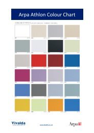
Aesthetics & colourThe landscape of colourAwareness of - and therefore care for - theenvironment is increasing steadily. Far morestress is being given to appropriate colourationof both urban and rural environments in allsectors – domestic, industrial, leisure, publicand commercial.Because colours used on buildings are neverseen in true isolation, they cannot beconsidered as absolute and unchanging.They are an integral part of their environmentin the most local and most general sense.As part of the language of building they have animportant role to play, as do form and material,in the correct and fluent placing of a structurein its appropriate context.Colour in contextIn some environments, colour has long beenused to influence or create mood andatmosphere, to change perception of roomshape or size and where appropriate, toexpress function.These kinds of influence can be extended tothe exterior on the larger scales both of localityand the environment as a whole.Colour as well as style of architecture is apowerful way of ‘contextualising’ structures –making them harmonious with or deliberatelydistinct from both large and small scaleenvironments. This process can be broadlydivided into 3 levels (see below).Alternatively, it may be important to find regionalsolutions that respect individual locations, byselecting colours to match the tones of thepredominant local materials.DetailThe colour and textures of cladding can bechosen to harmonise or deliberately contrastwith the other building materials to which it isadjacent.Local architectureIn most urban or suburban environments,the general architecture has evolved over asubstantial period and therefore has some sortof consistency of scale, material and colour.Choice of cladding type and colour can beimportant when establishing visual links withthese local themes.Wider contextIn an urban or commercial environment,cladding may be used as a dynamic expressionof architectural intent.26 <strong>Design</strong> considerations
Panel fixingsThe fixing method chosen can have afundamental and dramatic effect upon the finalappearance of the clad building.The 'visible fixing' systems – screw and rivetfixing – may be seen as providing anappearance somewhere between secret fixEmploying a secret fix method, for example, willresult in a sheer, smooth facade unobstructedby fixings.An edge retention system, on the other hand,focuses the eye upon the panel joints and willgive the facade a geometric feel, especiallyand edge retention. The smooth facade ofthe cladding will be punctuated by the heads ofthe rivets or screws, although, in practice, theselow profile fixings are virtually unnoticeable.Additionally, fixing methods can be combinedto create interesting design detail.Visible fixing screw or rivetSecret fixwhen a contrasting colour is chosen for theedge framing members.For example, a minimal amount of mechanicalfixing can be combined with structural adhesivebonding.The illustrations, right, show a diagrammatic view of thegeneric differences in appearance between some typicalfixing systems. Please contact our Technical Advisory Servicefor further information.Edge retentionAdhesive fix with squareboss at each cornerEconomic module sizesMarley Eternit high performance fibre cementcladding can be made to any module and offerthe architect and designer wide design3040freedom. Economics, however, play a significantpart in the selection of claddings and should beconsidered. When designing, the following2500information is aimed at providing the specifierwith guidance on the most economic materialusage from standard sheets.Sizes greater than half the maximummanufacturing lengths become progressivelyless economical in ratio to the distancedownwards from full length to half length asindicated on the charts. The cost involved infactory cutting of High Performance <strong>Cladding</strong>sto exact sizes is small in relation to the overallinstalled cost of cladding systems and it maybe prudent in some cases to have two smalleconomic panels rather than one largeuneconomical panel.4006008001220The shaded areas indicate the most uneconomic modules cut from a standard sheet.(Based on 1220 x 3040 sheet).152012201000800600400300For example an 800mm deep fascia would bemore economically clad using 1200mm panellengths rather than longer panels. The joints inthese cases can either be made a feature ofor hidden.<strong>Design</strong> considerations 27
Recommendeddesign procedureNatura, Brunel University, Uxbridge<strong>Design</strong>ers are advised to consider the following steps whencommencing a design incorporating Marley Eternit products.Reference should also be made to BS 8200 (The following information is provided for‘Code of Practice for the design ofguidance only. <strong>Design</strong>ers should ensure thatnon-loadbearing external vertical enclosures they make all the necessary calculations andof buildings’, also BS 6093 - ‘Code of Practice take into account all aspects of the specificfor the design of joints and jointing in building project design and location.)construction’, and to BS 8000: Part 6:Further information can also be found in:‘Workmanship on Building Sites: Code ofCWCT Standard for systemised buildingPractice for slating and tiling of roofs andenvelopes, and NHBC Standards 2008.claddings’.1. Checklegislation andplanning issues9. Produce projectspecification and drawings2. Establish topography andexposure of site and assess windand rain resistance (pages 32-33)8. Select fittings andaccessories to meetaesthetic and performancecriteria (pages 90-119)The decisionmaking process3. Assess performancerequirements: acoustics, thermal,fire, ventilation (pages 34-40)7. Determine fixingspecifications (pages 90-119)6. Select correctfixing method (pages 27, 90-119)4. Liaise with frameworkmanufacturer or structural engineerto determine support rail framingand design (page 32)5. Select cladding type(pages 44-89)28 <strong>Design</strong> considerations
Step 1: Legislation and planningGuidance on legislation is given on pages30-31. Planning permission may be necessaryin certain areas and is dependenton Local Authority policy and control.Step 2: Exposure, wind andrainEstablish the exposure zone of the site byreference to the map on page 33. This dividesthe UK into 2 categories of exposure to drivingrain and is based on rain penetration data fromBS 8104, ‘Code of practice for assessingexposure of walls to wind-driven rain’ andBRE Report 262 ‘Thermal insulation: avoidingrisks’. The map applies to buildings of up to12 metres in height at the ridge.Calculate the wind suction loading inaccordance with BS 6399: Part 2, ‘Code ofpractice for wind loads’.Step 3: Assess performanceagainst regulatory requirements<strong>Cladding</strong> performance criteria will varyaccording to design, building function etc.,Further guidance is shown on the followingpages: ‘Fire’, page 34, ‘Condensation andventilation’, page 35, ‘Acoustics’, page 35and ‘Thermal’, pages 36-40.Step 4: Framework andsupport railDetermine design of cladding and configurationof support rails with structural engineer andframework manufacturer.Ensure that the structure is adequate forthe total weight of the cladding as installed,and for the calculated wind loading and anyother relevant loading criteria (see page 32-33).Weights of panels are shown on theappropriate product pages.Step 5: <strong>Cladding</strong> selectionThe choice of cladding is a combinationof planning, aesthetic and performance criteria.The key factors are shape, size, colour, texture,material and sustainability, see pages 44-89.Step 6: Fixing MethodSelect a fixing method in accordance with theaesthetic and performance criteria.The panels may use visible screws or rivets, orbe secretly fixed. Edge retention systems or acombination of methods can be used to createdistinctive design detail, see pages 90-119.Step 7: Fixing specificationsA full fixing specification should be obtainedfrom the Technical Advisory Service, or byvisiting www.marleyeternit.co.uk.Step 8: Fittings & accessoriesCheck that any fittings or accessories specifiedare suitable for the design and its associatedperformance requirements by referring to thefixing systems page 90-119.Step 9: Produce project specificspecifications and drawings‡ Moreadvice E-mail info@marleyeternit.co.ukTel 01283 722588Further information on cladding withrespect to colour, shape, size, weights,is on the following pages:44-49 Natura50-55 Textura56-61 Pictura62-69 Operal70-81 Cedral Weatherboard82-85 BlucladNatura, New North Road, Islington Natura, used inside European commercial building<strong>Design</strong> considerations 29
SCOTTISH BUILDINGSTANDARDS AGENCYSCOTTISH BUILDINGSTANDARDS AGENCYThe Scottish Building StandardsThe Scottish Building StandardsLegislation, guidance& referenceBefore contemplating any cladding project, the designer andcontractor must be aware of the current legislation, the designrequirements and standards that govern and influence the style,parameters, performance, products and construction of theproject. The following section summarises many of the relevantdocuments, but is by no means exhaustive.StructureEngland and Wales:Part A ‘Structure’Scotland:Technical handbook,<strong>Section</strong> 1 ‘Structure’Northern Ireland:Part D ‘Structure’FireEngland and Wales:Part B ‘Fire Safety’Scotland:Technical handbook,<strong>Section</strong> 2 ‘Fire’Northern Ireland:Part E ‘Fire Safety’MoistureEngland and Wales:Part C ‘Site Preparation andResistance to Moisture’Scotland:Technical handbook,<strong>Section</strong> 3 ‘Environment’Northern Ireland:Part C ‘Site Preparation andResistance to Moisture’SoundEngland and Wales:Part E ‘Resistance to thepassage of sound’Scotland:Technical handbook,<strong>Section</strong> 5 ‘Noise’Northern Ireland:Part G ‘Sound insulationof dwellings’VentilationEngland and Wales:Part F1 ‘Means ofVentilation’Scotland:Technical handbook,<strong>Section</strong> 3 ‘Environment’ThermalEngland and Wales:Part L ‘Conservationof fuel and power’Scotland:Technical handbook,<strong>Section</strong> 6 ‘Energy’Northern Ireland:Part F ‘Conservationof fuel and power’TECHNICAL HANDBOOKNON-DOMESTICScottish TechnicalHandbooksThe sections referred to aboveare contained in the twoScottish technical handbooks,one covering domesticconstruction, the othernon-domestic.TECHNICAL HANDBOOKNON-DOMESTIC30 <strong>Design</strong> considerations
Building RegulationsThese are mandatory regulations and, inEngland and Wales, are generated andapproved by the Department for Communitiesand Local Government (DCLG).In Scotland they are generated and approvedby the Scottish Executive and in NorthernIreland, by The Office Estates and BuildingStandards Division (OBD).They must be complied with for all new-buildand a great deal of refurbishment work.They consist of the Building Regulations 2000(as amended) for England and Wales, theBuilding (Scotland) Regulations 2004, and theBuilding Regulations (Northern Ireland) 2000.Compliance with these regulations is theresponsibility of the building designer, whomay be the owner of the building, his appointedarchitect, a structural engineer appointed bythe owner or his architect or, in the case ofsmall buildings, the actual builder.The increasing complexity of construction andthe codes that govern design hasled many building designers to request thespecialist services of a cladding or buildingenvelope designer.The Approved Documents of the BuildingRegulations (England and Wales), the TechnicalHandbooks (domestic and non-domestic)(Scotland) and the Technical booklets (NorthernIreland) provide practical guidance for some ofthe common building situations in respect of therequirements for materials and workmanship.Copies of the Approved Documents thataccompany the Building Regulations 2000(as amended) for England and Wales can bedownloaded from the the Department forCommunities and Local Government (DCLG)web site (www.communities.gov.uk) or obtainedfrom RIBA Bookshops, 15 Bonhill Street,London EC2P 2EA. (Tel 020 7256 7222, Fax020 7374 2737).Copies of the complete set of Handbooks thataccompany the Building (Scotland) Regulations2004 for Scotland can be downloaded from theSBSA web site (www.sbsa.gov.uk). Follow thelinks to 'Archive', 'Standards and Guidance'then 'Technical Standards'. They can also beobtained on a CD-Rom from the Scottish BuildingStandards Agency (SBSA), Denholm House,Almondvale Business Park, Livingston, EH54 6GA(Tel 01506 600400, Fax 01506 600401.British StandardsA British Standard is a published documentthat contains a technical specification or otherprecise criteria designed to be usedconsistently as a rule, guideline, or definition.They are a summary of best practice and arecreated by bringing together the experience andexpertise of all interested parties – the producers,sellers, buyers, users and regulators of aparticular material, product, process or service.Standards are designed for voluntary use anddo not impose any regulations. However, lawsand regulations may refer to certain standardsand make compliance with them compulsory.The principal British Standards relevant tothis document are:BS 5534 Gives recommendations for thedesign, materials, application, installation andperformance of slates, tiles, shingles andshakes. It also covers their associated fittingsand accessories for use in the construction ofpitched roofs and vertical cladding applications.(BS 5534 should be read in conjunction withBS 8000-6)BS 5588 Fire precaution in the design,construction and use of buildings.BS 6093: 2006 <strong>Design</strong> of joints andjointing in building construction.BS 8200: 1985 Code of Practice for designof non-loadbearing external vertical enclosuresof buildings.BS 476-6: 1989 Fire tests on building materialsand structures – Method of Test for firepropagation for products.BS476-7: 1997 Fire tests on building materialsand structures – Method of test to determinethe classification of the surface spread of flameof products.BS EN 12467: 2004 fibre cement flat sheets,product specification and test methods.Provides information on the technicalrequirements.BS EN 13501-1: 2002 fire classification ofconstruction products and building elements –Classification using test data from reaction tofire tests.BS 8000-6: ‘Workmanship on building sites.Code of practice for slating and tiling of roofsand claddings’. Applies to the laying and fixingof claddings and their associated fixings andaccessories. Common Arrangement of Work<strong>Section</strong> (CAWS) classifications H60, H61and H65.BS 5250: ‘Control of Condensation in Buildings’Describes the causes and effects of surfaceand interstitial condensation in buildings andgives recommendations for their control.Health and safetyTo ensure safe working practices duringconstruction, the designer should considerrelevant safety regulations. These include theConstruction (<strong>Design</strong> and Management)Regulations and the Health and SafetyExecutive’s approved code of practice formanagement of health and safety at work.Certain advisory bodies such as the NationalHouse Building Council (NHBC), LossPrevention Council (LPC), Building ResearchEstablishment Ltd (BRE) and Timber Researchand Development Association (TRADA) alsoproduce recommendations and guidance onconstruction which should be considered.‡ Morepages 120-123 ‘Sitework’134 ‘References’<strong>Design</strong> considerations 31
Wind resistanceWind forces on buildingsEach year as many as 200,000 buildings in theUK may be damaged by gales. Roof damagerepresents by far the largest sector of the totalnumber of building elements affected.Wind can affect a building in a patterndetermined not only by climate and topography,but also by wind direction, the shape of thebuilding and the pitch of the roof.Wind blowing at 90° to a building is sloweddown when it hits the surface of the building,with a consequent build-up of pressure. At thesame time, it is deflected around the end wallsand over the roof, creating areas of negativepressure or suction. The stronger the wind, thegreater the suction.The force of the wind acting on the windwardface of a building creates a positive pressure,although, even here, there are areas wheresuction develops. Leeward faces are alwayssubject to suction.<strong>Design</strong> for wind loadingThe standard method in BS 6399-2 ‘Loadingfor buildings – Code of practice for wind loads’should be used to determine the basic windspeed of the site, which is then used tocalculate the effective wind speed and dynamicwind pressure on the envelope, by applying aseries of factors to account for terrain,topography, building height and length etc.Wind loadingCalculate the dynamic pressures of the wind(including the appropriate pressure coefficientsfor the building) in accordance with BS 6399-2wind loading or EN 1991-1-4.The spacing of the profiles and brackets isdetermined by calculation once the wind forceson the structure have been determined. TheVentisol system has been wind tested by theBuilding Research Establishment (BRE) and isclassified as permeable when applied tonominally impermeable walls. In this situation, alarge proportion of the external wind pressure isable to leak through the cladding to act directlyon the building wall, relieving the loads on thecladding. The provisions of all current codes ofpractice, including that for the UK are intendedto give design loadings for typical impermeablebuildings and do not provide data in therequired form to enable the loading onpermeable overcladdings to be assessed.The response of the Ventisol overcladdingsystem to wind loading has been determined bydirect measurements. A system performancespecification has been defined with which theactual performance is shown to comply.Using this system performance, a computerbased numerical model of the behaviour of thesystem when installed on a building has beendeveloped and run for a number of typicalinstallations. It is concluded that the maximumnett suction on the standard system withoutfire-stops can be taken as one-half of thedesign external wind pressure.Directions of pressuresgenerated by wind forceReaction of wind flow to obstruction+ –suctionzonewind30° andabove–suctionzonewind+30° andbelowPressure distribution in relation to roof pitch32 <strong>Design</strong> considerations
‡ Moreadvice E-mail info@marleyeternit.co.ukTel 01283 722588webmarleyeternit.co.uk/claddingChoice and type of anchorConsideration must be given to:Basic wind speed*Basic wind speedsa) the strength and state of the existingstructure.b) the capability of the chosen anchor to acceptthe live and dead loads imposed, and anadequate safety factor.Aircraft vortices<strong>Cladding</strong> near airports can experience high localwind load forces due to air vortices createdby certain aircraft when taking off and landing,which may be greater than the calculated windloads to BS 5534. <strong>Design</strong>ers should seekadvice from the Airport Authority PlanningDepartment when designing in these locations.31 Basic wind speed Vb (in m/s)31* Derived from BS 6399-2Note: Channel Islands basic wind speed = 24 m/s30292824252627InvernessAberdeen23ObanPerthDundee25GlasgowEdinburgh2625Londonderry24CarlisleNewcastleBelfast23Preston2423LeedsYorkKingstonupon-HullLiverpoolManchesterSheffieldSwansea22StokeNottingham21LeicesterBirminghamAberystwythNorthampton20OxfordBedfordNorwichIpswich232425CardiffBristolLONDONBournemouthBrightonPlymouth2423<strong>Design</strong> considerations 33
SCOTTISH BUILDINGSTANDARDS AGENCYThe Scottish Building StandardsFire safety, acoustics,condensation & ventilationFire safetyBuilding RegulationsThe relevant document isApproved Document B, ‘FireSafety.’Key to external wall surface classificationRelevant boundaryNo provision in respect of theboundaries indicatedClass 0 (National Class) or classB-s3, d2 or better (European class)Index (I) not more than 20 (Nationalclass) or class C-s3 d2 or better(European class). Timber claddingat least 9mm thick is alsoacceptable. (The index I relates totests specified in BS 476: Part 6).B4 – Provisions for external surfaces of wallsBuildingheightlessthan18mUp to10mabovegroundUp to 10mabove a roof orany part of thebuilding towhich the publichave accessLess than1000mm1000mmor more1000mmor more1000mmor moreA. Any building B. Any buildingother than C.C. Assembly or recreationbuilding of more than one storeyBuildingheightlessthan18mAny dimensionover 18mUp to 18mabove groundNotes:The National classifications do not automatically equatewith the equivalent European classifications, thereforeproducts cannot typically assume a European classunless they have been tested accordingly.When a classification includes ‘s3, d2’, this means thatthere is no limit set for smoke production and/or flamingdroplets/particles.Scottish RegulationsLess than1000mmLess than1000mm1000mmor more1000mmor moreTECHNICAL HANDBOOKNON-DOMESTIC‘A2’ classified materials areclassified as non-combustible.Marley Eternit fibre cementcladding products are allA2-s1-d0.D. Any building E. Any building34 <strong>Design</strong> considerations
AcousticsBuilding RegulationsThe relevant document governingacoustic design, especially fordwellings, is Building RegulationsApproved Document E‘Resistance to the passage ofsound’ within which, the relevantsections are:E1: Protection of sound from other parts ofthe building and adjoining buildings.E2: Protection against sound within a dwellinghouse.Other documentation, such as (HTM) Healthand Technical Memoranda 56 and 2045 forhospitals and Building Bulletin (BB) 87 and93 for schools, offers guidance on meetingBuilding Regulations for specific building types.BS 5821 detailing the ‘methods for rating thesound insulation in buildings and of buildingelements’, is also relevant.Resistance to the passage of soundApproved Document E deals with theresistance of both airborne and impact soundgenerated within buildings, and requires thatdwellings, flats and rooms for residentialpurposes shall be designed and constructedin such a way that they provide reasonableresistance to sound from other parts of thesame building and from adjoining buildings.Separate requirements apply to schools, whereeach room or space in the building shall bedesigned so that it has the acoustic conditionsand the insulation against disturbance by noiseappropriate to its intended use.Further information can be obtained byreference to BS 8233 ‘Sound insulation andnoise reduction in buildings’ and BS EN ISO717-1 ‘Acoustics – Rating of sound insulationin buildings and of building elements. Part 1Airborne sound insulation’, and BS EN ISO717-2 ‘Acoustics – Rating of sound insulationin buildings and of building elements. Part 1‘Impact sound insulation’.Condensation and ventilationBuilding RegulationsApproved Document C ‘Sitepreparation and resistance tomoisture’ contains informationrelating to the control of andresistance to condensation inbuildings.Approved Document Part F1‘Means of ventilation’.Contains information on theprovision of natural andmechanical ventilation forbuildings. This is with specificreference to the reduction andremoval of condensation.Control of condensationCondensation has become more of a problemwith the increase in highly insulated buildings.Moreover, changes in lifestyle have led to higherlevels of water vapour in modern buildings. Thiswater vapour naturally ascends to the roofspace, where it condenses on contact withcooler surfaces. Further condensation is likely tobe caused by climatic conditions, and mayeventually result in timber rot, metal corrosionand damage to insulation and fittings.Detailed information on methods to controlharmful condensation is given in BritishStandard BS 5250: ‘Code of practice forcontrol of condensation in buildings’ <strong>Section</strong>8.4 ‘Roofs’. Prevention of condensation in roofvoids is best achieved by the provision ofnatural air ventilation.BS 5250 states that the designer shouldtake account of the following moisturesources in buildings:• water incorporated during the constructionprocess (including precipitation);• precipitation after construction;• water vapour arising from the occupantsand their activities;• temporary condensation occurring whencold weather conditions are followed bywarm, humid weather.<strong>Design</strong> considerations 35
Thermal insulationBuilding RegulationsThe relevant documents areApproved Document L1A‘Conservation of fuel andpower in new dwellings’;L1B ‘Conservation of fuel andpower in existing dwellings’ ;L2A ‘Conservation of fuel andpower in new buildings otherthan dwellings’ and L2B‘Conservation of fuel andpower in existing buildingsother than dwellings’ forEngland and Wales and<strong>Section</strong> 6 ‘Energy’ (domesticand non-domestic) for Scotland(see separate leaflet).The Building Regulationsprescribe high standards ofbuilding fabric insulation forfloors, walls and roofs as wellas space heating, lighting, andhot water controls so as to limitthe heat loss from the building .The government have improved the regulationsin terms of energy efficiency to create a 40%improvement in reduction of carbon emissionssince 2002.The Part L Approved Document took effect asof 1st October 2010, The Secretary of Stateissued the document to provide practicalguidance on ways of complying with the energyefficiency requirements and regulation of theBuilding Regulations 2000 for England andWales, as amended.ComplianceThe new requirements of the Regulations aredesigned to reduce carbon emissions from newbuildings and to improve the performance ofexisting buildings where new work is carried out.Parts L1A, L1B, L2A and L2B have a singlemethod of compliance. This is expressed inCO 2 emissions in kg/m 2 /year and is calculatedby the SAP (Standard Assessment Procedure)2009 method for dwellings and the iSBEMmodel for non-dwellings or all buildings over450m 2 . This involves a series of calculationsbased on heat loss of elemental areas, volumesof spaces to be heated, heating systems, solargain etc., for which computer software modelsare available.In terms of the external walls and claddings,designers will no longer be able to specify“walls to comply with Part L” on drawings or inspecifications. Products can no longer belabelled ‘Part L compliant’, as not one elementor product can meet Part L withoutconsideration for all other elements in theconstruction and energy use of the building.The design process is now more complicatedas a number of assumptions have to be madeat the design stage when inputting into the SAPor iSBEM calculations before the specificationcan be finalised, to see if the building will becompliant with Part L compared to a notionalbuilding.The main variables to consider are:-• External envelope U-values for walls,roofs and floors• Thermal bridging details• Ventilation strategy for ensuring fresh air• AirtightnessThe following sections briefly summarise thecontent of the four parts of Part L –Part L1A - ‘New dwellings’The target CO 2 Emission Rate for dwellingsup to 450m 2 is calculated using SAP (StandardAssessment Procedure) 2005 for a ‘notional’dwelling of the same size and shape as the‘actual’ dwelling (based on set construction rules).The Simplified Building Energy Model (SBEM)will be used for larger dwellings.The Dwelling Emissions Rate (DER) mustbe no higher than the target. Two phases ofcalculation for the DER are required:1 <strong>Design</strong> calculations presented in a reportto Building Control that defines the criticaldesign features2 Following dwelling pressure testing, a finalcalculation to confirm that the buildingcomplies ‘as built’Part L1B – ‘Existing dwellings’This includes most extensions, materialchanges of use, material alterations, provisionof controlled fittings and services and provisionor renovation of a thermal element. Therecommended maximum U-values for anextension may be varied on condition that it isno worse overall than a similar extension builtto the standards and that the defined maximumU-values are not exceeded.SAP 2009 can be used to demonstrate thatCO 2 emissions from a dwelling plus anextension taken together are no worse than thatof the dwelling complying with regulations plus aseparate extension complying with regulations.This process may involve improvements to theexisting thermal elements, such as walls, roofsand floors, which must comply with Part L1Bstandards.Limiting U-value standards (W/m 2 K) (Part L1A New Dwellings)ElementArea-weighted averageEternal wall 0.30Party wall 0.20Roof 0.20Floor 0.25Windows 2.00* Excluding display windows and similar glazing. There isno limit on design flexibility for these exclusions but theirimpact on CO 2 emissions must be taken into accountin calculations.† The U-values for roof windows and rooflights in this tableare based on the U-value having been assessed with theroof window or rooflight in the vertical position. If a particularunit has been assessed in a plane other than vertical, thestandards given in the Approved Document should bemodified by making an adjustment that is dependent onthe slope of the unit following the guidance given in BR 443'Conventions for U value calculations'. BRE.2006.36 <strong>Design</strong> considerations
Part L2A - ‘New non-dwellings’There are 5 key criteria for compliance:1 CO 2 emissions must be less than target value2 The thermal performance of building fabricand services must satisfy minimum standards3 Summer time solar gains must be controlled4 Pressure testing and ‘Quality of Construction’will be mandatory5 Building users should be supplied withsufficient information to operate the buildingin the most energy efficient manner.Significant improvements in carbon dioxideemissions are required when comparing thenotional and actual results. In general termsthese represent the improvements to the levelsstated in the 2006 regulations:Heated and naturally ventilated: 23.5%Heated and mechanically ventilated: 28%Air conditioned: 28%Again, two phases of calculation for emissionsrate are required:1 <strong>Design</strong> calculations presented in a reportto Building Control2 Following full building pressure testing,a final calculation to confirm that thebuilding complies ‘as built’.Part L2B – ‘Existing non-dwellings’This applies to extensions and subsequent fitout works, change of use, material changes,work on controlled services etc. New buildingfit outs for existing buildings should complywith new building regulations.Part L 2006 introduces ‘ConsequentialImprovements’ which may in some situationsrequire the upgrading of windows, boilers,air-conditioning and lighting as well as theinclusion of energy metering systems.For all partsWhere possible, LZC (Low and Zero Carbon)systems should be installed.Unit energy costs for each fuel type aredetailed in the Approved Document and shouldbe used for assessing the feasibility of variousimprovements.Airtightness/air leakagePart L 2010 provides requirements for buildingsto be tested for air leakage once completed.Testing is carried out using pressurised fansand consultants, to ensure that as well as thetheoretical heat loss calculations, the building isnot leaky and wasting energy through gaps andcracks due to construction methods.Workmanship and detailing on site to ensurethat a permitted air leakage of 10m 3 /hour/m 2@ 50 Pa is not exceeded when tested.The building designer has to make anassumption of what the level of airtightness hecan achieve from his building at the designstage. This is inputted into the calculation for hisheat loss/SAP calculations. Should the buildingbe found to be higher in terms of air leakage,then remedial measures must be taken to ensurethe building meets the required design value.<strong>Design</strong> considerationsThere are a number of factors to consider whendesigning buildings that are to meet the newPart L requirements. These will involve the typesof windows, doors, rooflights, solar gain, framefactor, air infiltration, U-Values, type of glass,total area and aspect of the dwelling. Thedesigner will also be required to consider theheating system, the impact of any mechanicalventilation systems, along with the controls, andany low and zero carbon technologies, e.g.solar PV, wind power. Credits will be achievedfor the use of ‘low carbon’ and energy savingproducts, which in many cases will be thepreferred route to compliance. This will involvean assessment of the whole buildingperformance and not just each individual value.In order to improve the quality of design details,a set of ‘Accredited Construction Details’ havebeen published to accompany the new Part L.These are updated versions of 2002 Thermal‘Robust Details’, and if approved overspecifications could limit the requirement foron-site testing.Attention is given to the provision of suitableinsulation to prevent heat loss and cold bridgesin roof construction. Guidance measures toprevent moisture ingress, condensation and airleakage are incorporated into the constructiondetails for walls, floors and roofs, with particularattention being given to the junctions of walls tofloors and walls to roofs.As insulation levels increase so does thepotential risk of condensation, and so designersshould consider the recommendations withregard to the prevention of condensation in ‘cold’roof voids contained in BS 5250: 2002 AMD 1,which is also referenced in Approved DocumentC of the Building Regulations.<strong>Design</strong> considerations 37
Thermal design detailsnew structures – housing38 x 100mm batten 6Blockwork wall• Marley Eternit external cladding• 38 x 50mm and 38 x 100mmtimber battens• Counterbattens 50 x 50mm0.25u-value50 x 50mm counterbatten 450mm PIRinsulationpartial fill 338 x 50mm batten 5Air gap 7• Single skin 440 x 215mmAircrete blocks• 50mm PIR insulation215mm TurboAircrete blocks 212.5mm Plasterboardon dabs 1Notes• Internal wall should be 12.5mmplasterboard on dabs1Marley Eternit<strong>Cladding</strong> 84 5 2 3 7 6 8Fibre cement sheathing 5Timber frame wall• Marley Eternit external cladding• 38 x 50mm timber battens0.29u-value140mm Knauf InsulationFrameTherm 35 4Timber stud 3Knauf InsulationBreatheline 2Air gap 6• 140 x 60mm timber studsPlasterboard 1• 140mm Knauf FrameTherm35 insulation between studs• Knauf Insulation Breatheline vapourcontrol layer between plasterboardand timber studs1 238 x 50mmtimber batten 7Marley Eternitcladding ding 83 4 5 6 7 838 <strong>Design</strong> considerations
Thermal design detailsnew structures – commercial, education or healthcareThermostop pad 7Aluminium frame fixing system 8Lightweightsteel frame• Marley Eternit external cladding• 125mm stone mineral wool• Ventisol or similar framing system• Bluclad cement board• 100 x 75mm ‘C’ sections• 90mm glass mineral wool• Vapour control layer• Internal wall should be 2 layersof 12.5mm plasterboard on dabs0.23u-value90mm insulation 3Vapour control layer 22 layers ofplasterboard 1120mm insulation 6Bluclad cement board 5100 x 75mm ‘C’ <strong>Section</strong>s 41 2 3 4 56mm gap 930mm gap 10Marley Eternit<strong>Cladding</strong> 116 7 8 9 10 11Concrete wallconstruction• Marley Eternit external cladding• Ventispan framing system• 130mm PIR insulation• Structural concrete slab0.14u-valueAir gap 5130mm PIR insulation 4Ventispan system 3Thermostop pad 2Precast concrete wall 1• Steel framing infill system (between floors)Notes• A very wide variety of internal wall finishingoptions are available, many of which willincorporate further layers of insulation.126mm gap 6Marley Eternitcladding 73 4 5 6 7<strong>Design</strong> considerations 39
Thermal design detailsupgrading existing structures and overcladdingBrickwork wall• Marley Eternit external cladding• Ventisol fixing system• Air gap• 80mm Rockwool RainscreenDuo-slab mineral wool• 9” solid brick wall (laid as headersand stretchers)0.35u-valueupgrade2.00u-valueFixing system 29” solid brick wallheaders and stretchers 180mm RockwoolRainscreen Duo-slabmineral wool 3Airgap 4Notes:• 9” solid walls are common in pre-1930 houseconstruction and the brick bonding can be in anumber of configurations• U-values of these types of wall are typically1.9-2.2 W/m 2 K• Other fixing systems can also be used• Greater (or lesser) depths of insulant canbe accommodated1Marley Eternitcladding 52 3 4 5Block and brickwork wall• Marley Eternit external cladding• Ventisol fixing system• Air gap• 80mm Rockwool RainscreenDuo-slab mineral wool• Brick outer skin• Cavity not insulated0.33u-valueupgrade1.50u-valueFixing system 4Brickwork 3Empty cavity 2Blockwork 180mm RockwoolRainscreen Duo-slabmineral wool 5Airgap 6• Brick inner skinNotes:• U-values of these types of un-insulatedwall are typically 1.0-1.6 W/m 2 k• Other fixing systems can also be used• Greater (or lesser) depths of insulantcan be accommodated1Marley Eternitcladding 72 3 4 5 6 740 <strong>Design</strong> considerations
Natura, Barking Foyer, Barking<strong>Design</strong> considerations 41