User Manual - PURE4C
User Manual - PURE4C
User Manual - PURE4C
- No tags were found...

You also want an ePaper? Increase the reach of your titles
YUMPU automatically turns print PDFs into web optimized ePapers that Google loves.
About this DocumentsinaCAMList of FiguresFigure 1: The Remote Head ............................................................................................................................... 9Figure 2: The Base Unit .................................................................................................................................... 10Figure 3: The Control Panel ............................................................................................................................. 11Figure 4: Arrangement of the Terminals ........................................................................................................ 12Figure 5: Pin Assignment of the 10-Pin AUX Terminal ................................................................................... 15Figure 6: AUX Connection Example – Remote Control Panel ........................................................................ 16Figure 7: AUX Connection Example – External Timecode Generator ........................................................... 16Figure 8: AUX Connection Example – External Exposure Trigger ................................................................. 17Figure 9: GenLock Example Setup with two sinaCAM Base Units................................................................. 18Figure 10: Standard Single-Link Setup .............................................................................................................. 19Figure 11: Advanced Dual-Link Setup ............................................................................................................... 19Figure 12: Broadcast Setup ................................................................................................................................ 19Figure 13: Adjusting the Lens Scale Position .................................................................................................... 20Figure 14: Flange Back Distance Adjustment ................................................................................................... 21Figure 15: The Scroll Wheel ............................................................................................................................... 22Figure 16: Standard/Alternative Setting ............................................................................................................ 23Figure 17: Saving of New Settings ..................................................................................................................... 23Figure 18: The Menus at a Glance ..................................................................................................................... 24Figure 19: HOME Menu ...................................................................................................................................... 25Figure 20: White Balance Adjustment Screen .................................................................................................. 27Figure 21: <strong>Manual</strong> White Balance Adjustment Screen..................................................................................... 28Figure 22: Rec. 709 vs. S-Log Gamma Curves ................................................................................................... 29Figure 23: LEVEL Menu ....................................................................................................................................... 30Figure 24: MODE Menu ...................................................................................................................................... 31Figure 25: GenLock Example Setup with two sinaCAM Base Units and their Settings .................................. 33Figure 26: MTF Graph for Sharpening Function ............................................................................................... 34Figure 27: SYSTEM Menu .................................................................................................................................... 35Figure 28: INFO Screen ...................................................................................................................................... 35Figure 29: SERVICE Menu ................................................................................................................................... 36Figure 30: Base Bars test image with camera head 1/2 indicator field highlighted ...................................... 36Figure 31: USB Menu .......................................................................................................................................... 37Figure 32: Web Manager - Login ........................................................................................................................ 38Figure 33: Web Manager - Summary ................................................................................................................ 39Figure 34: Web Manager - Network Settings .................................................................................................... 40Figure 35: Web Manager - Clock Adjust ............................................................................................................ 40Figure 36: Web Manager - Update Gamma LUT............................................................................................... 41Figure 37: Web Manager – Update Firmware ................................................................................................... 42Figure 38: Web Manager – Firmware Now Updating ....................................................................................... 42Figure 39: Base Unit Measurements ................................................................................................................. 44Figure 40: Remote Camera Head Measurements ............................................................................................ 444 Rev.: D <strong>User</strong> <strong>Manual</strong>
sinaCAMSafety Instructions2. Safety Instructions2.1 Warning Signs and IndicationsCAUTIONIndicates a hazardous situation which, if not avoided, could result in minor or moderate injury.NOTICEIndicates a potentially hazardous situation which, if not avoided, may result in property damage.2.2 General SafetyRead and follow all safety and operating instructions before installing and operating the camerasystem.2.3 Specific SafetyOnly use the type of power source specified for this camera system. The use of a wrong power sourcecould damage the camera system and/or cause fire or electric shock!Do not open the housing of the camera system. Risk of electric shock!Do not open the housing or attempt to repair or modify any part of the camera system. Repairs mustonly be carried out by authorized sinaCAM service centers.Do not store the camera system near a strong magnetic field, or in areas where it would be subjectedto direct sunlight, extreme temperatures, high levels of humidity or severe vibrations.Do not use the camera system outside the specified operating temperature range.Keep all liquids away from the camera system. Do not place containers with liquids on top of thecamera housing. Risk of fire, electric shock and/or damage!Do not use the camera system in places where it could come in contact with water, moisture, steamor dust. This could damage the camera system and/or cause fire or electric shock!Unplug the power cable by the plug, do not pull the cable.Unplug all cables before transporting the camera system or storing it inside a camera case.Always put the protection cap onto the lens mount when transporting the remote camera headswithout lenses.Do not allow laser beams to enter the camera lens or the lens mount opening, as this could causedamage to the CCD sensor.<strong>User</strong> <strong>Manual</strong> Rev.: D 7
Regulatory CompliancesinaCAM3. Regulatory ComplianceThe sinaCAM base station and the sinaCAM remote heads comply with thefollowing regulations:RoHSLow Voltage Directive (LVD), 2006/95/ECElectromagnetic compatibility (EMC):– 2004/108/EC– FCC 47 CFR Part 15 Subpart B Class BFCC NOTEThis equipment has been tested and found to comply with the limits for a Class B digital device, pursuantto part 15 of the FCC Rules. These limits are designed to provide reasonable protection against harmfulinterference in a residential installation. This equipment generates, uses and can radiate radio frequencyenergy and, if not installed and used in accordance with the instructions, may cause harmful interferenceto radio communications. However, there is no guarantee that interference will not occur in a particularinstallation. If this equipment does cause harmful interference to radio or television reception, which canbe determined by turning the equipment off and on, the user is encouraged to try to correct the interferenceby one or more of the following measures:– Reorient or relocate the receiving antenna.– Increase the separation between the equipment and receiver.– Connect the equipment into an outlet on a circuit different from the one the receiver is connected to.– Consult the dealer or an experienced radio/TV technician for help.The user is cautioned that changes or modifications not expressly approved by the party responsible forcompliance could void the user’s authority to operate this equipment.4. DisposalFor European Union member states only:The use of this symbol indicates that this product must not be disposed of with household waste.By ensuring this product is disposed of correctly, you will help prevent negative consequences forthe environment and human health. At the end of its lifespan, take the product to an appropriate recyclingstation. For more information about correct disposal of electrical and electronic equipment please contactyour local authorities or your supplier where you purchased the product.8 Rev.: D <strong>User</strong> <strong>Manual</strong>
DescriptionsinaCAM6.2 Base Unit HDC1-200Figure 2: The Base UnitTable 3: Elements of the Base UnitItem Designation DescriptionA Control panel Controls and graphical user interface displayB Mounting points M4 thread for attaching a handle or to fix the base unit to amounting plateCSystem battery compartmentThe system battery supplies power to the internal clock only. Itdoes not supply the camera with power. Do not open the systembattery compartment. Replacement of the system battery mustonly be carried out by authorized sinaCAM service centers.D Rear panel Panel with all terminals to connect equipment10 Rev.: D <strong>User</strong> <strong>Manual</strong>
sinaCAMDescription6.2.1 The Control PanelFigure 3: The Control PanelTable 4: Controls and their FunctionsItem Designation DescriptionA USB 2.0 port For frame grabbing to a USB stick and software/firmware updates(update functionality only with December 2012 firmware or later)B Display Graphical user interface displayC F1 button To select a menu item as displayedD Power switch Turns power ON or OFFE Power LED Glows red when the unit is connected to the power supply, andglows green when the unit is powered onF Arrow buttons To select a menu item as displayedG F2 button To select a menu item as displayedH Scroll wheel Scroll wheel and pushing button to navigate through the menus andselect options<strong>User</strong> <strong>Manual</strong> Rev.: D 11
InstallationsinaCAM7.4 Calculation of Maximum Cable LengthThe maximum cable length between remote camera heads and base unit is limited by the signalattenuation and the conductor DC resistance of the used cable type.Maximum cable length as limited by signal attenuation (rule of thumb):Max. cable length = 25 dB / attenuation at 1.5 GHzMaximum cable length as limited by conductor DC resistance (rule of thumb):Max. cable length = 8 Ω / conductor DC resistanceExample calculation for Belden 1505F Flexible cable:– Nom. attenuation at 1.5 GHz: 13.300 dB / 100 ft– Nom. conductor DC resistance: 12.2 Ω / 1000 ftMax. cable length = 25 dB / (13.300 dB /100 ft) = ~188 ft (57 m)Max. cable length = 8 Ω / (12.2 Ω / 1000 ft) = ~656 ft (200 m)The lower of the two values determines the approximate maximum cable length, in this example 188 ft(57 m).7.5 Connecting the Hardware Make sure that all hardware to be installed is switched off. Connect all hardware to the base unit. Switch on all hardware and the base unit.14 Rev.: D <strong>User</strong> <strong>Manual</strong>
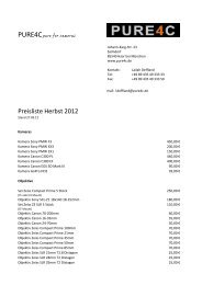
sinaCAMInstallation7.6 Connecting AUX DevicesThe 10-pin AUX terminal enables the connection of a remote control unit, iris control devices, timecodesignals or an exposure trigger signal.7.6.1 Pin Assignment of the 10-Pin AUX TerminalFigure 5: Pin Assignment of the 10-Pin AUX TerminalTable 6: Pin Assignment of the 10-Pin AUX TerminalPin no.Assignment1 5 V out2 GND3 TxD (RS-232) or Tx+ (RS-485)4 RxD (RS-232) or Rx+ (RS-485)5 Trigger Out6 Iris Control (PWM)7 Trigger In8 Timecode In9 CTS (RS-232) or Rx- (RS-485)10 RTS (RS-232) or Tx- (RS-485)Connector type:ODU MINI-SNAP G51L0C-P10QC00-A000Mating connector:E.g., ODU MINI-SNAP S11L0C-P10MCC0-6200<strong>User</strong> <strong>Manual</strong> Rev.: D 15
sinaCAMInstallation7.6.4 Exposure Trigger InterfacesinaCAM can be connected to an external exposure trigger generator. This is useful for, e.g., rotatingmirror shutter integration or other applications where exact sensor timing is essential.Note: The "GenLock"-mode must be set to "ExpTrgIn" to enable this feature (see chapter 9.4.3GenLock).A falling edge on the Trigger In pin triggers the start of sensor exposure, a risingedge stops the sensor exposure. In other words: The exposure length is controlled viathe negative pulse with of the Trigger In signal while the frame rate is controlled viathe frequency.Max. ratings:V high : 2.0 to 5.0 VV low : 0 to 0.8 VNegative pulse width: min. 1 usPositive pulse width: min. 10 msFrequency: max. 60 Hz (60 fps)Slew Rate: max. 2.5 nssinaCAM signals the actual sensor timing on the Trigger Out pin with the same meaning of the edges asdescribed above.Figure 8: AUX Connection Example – External Exposure Trigger<strong>User</strong> <strong>Manual</strong> Rev.: D 17
sinaCAMInstallation7.8 Connection ExamplesFigure 10: Standard Single-Link SetupFigure 11: Advanced Dual-Link SetupFigure 12: Broadcast Setup<strong>User</strong> <strong>Manual</strong> Rev.: D 19
InstallationsinaCAM7.9 Installing Lenses Attach C-mount lenses, suitable for 2/3” CCD cameras, to the standard C-mount thread of the remoteheads. In case of B4-mount or PL-mount lenses use the corresponding adapters (option).7.10 Adjusting the Lens Scale PositionDepending on filming situations, it can be necessary to equip a lens at a different angle than usual for thelens scale to remain readable. For this, sinaCAM remote camera heads support 12 different positions forthe lens mount, each 30° apart. The lens mount is held in the chosen position by the lens mount lock, withthe lens scale on top by default.Figure 13: Adjusting the Lens Scale PositionTo adjust the lens scale position follow these steps: Remove the screw from the lens mount lock’s lower screw hole, then partially screw it into the upperone (1).Note: The screw will not go all the way in. Grip the screw head to pull out the lens mount lock (2). Make sure the locking lever is in the open position (3). You can now adjust the position of the lens (4).Note: Inside, the lens mount is equipped with 12 holes (each 30° apart) forthe lens mount lock. Choose one of the valid positions, then reinsert the lens mount lock (5) to fixthe lens mount in its place. Move the screw back into the lower screw hole of the lens mount lock andtighten it (6). Then move the locking lever back into the closed position (7).20 Rev.: D <strong>User</strong> <strong>Manual</strong>
sinaCAMInstallation7.11 Adjusting the Flange Back DistanceIf the focus is sharp when zoomed in, but soft when zoomed out, the back focus may need adjustment.sinaCAM remote heads allow for easy back focus adjustment by changing the flange back distancebetween the rear of the lens and the CCD. Use typical back-focusing techniques, e. g. a test chart or aback focus collimator.NOTICEWrong flange back distance adjustment can cause unsatisfactory shooting quality. Flange back distanceadjustment should only be performed by experts.Figure 14: Flange Back Distance AdjustmentTo adjust the flange back distance follow these steps: Lift up the locking lever (A). Turn the adjustment ring (B) until the flange back distance is accurately set(± 1 rotation = ±250 µm):– To decrease the distance turn to the right (-).– To increase the distance turn to the left (+). Push down the locking lever. Check the adjustment with a control measurement.<strong>User</strong> <strong>Manual</strong> Rev.: D 21
OperationsinaCAM8. Operation8.1 Switching ON and OFFAfter the base unit is connected to the power supply, the power LED glows red.Switching ON Push the power switch.– The power LED of the base unit changes from red to green.– The HOME menu screen comes on.– The system LED of the remote head lights up in orange, starts flashing green and finally glowsgreen continuously.Note: The system LED of the remote head can indicate additional status information. For moreindications refer to chapter 11 Remote Head System LED Indications.Switching OFF Push and hold the power switch for about 4 seconds.– The power LED of the base unit changes from green to red.– The display goes off.– The system LED of the remote head goes off.8.2 Using the Menus Use the arrow buttons and F1/F2-buttons to select menu items asdisplayed. Use the scroll wheel to select and to confirm settings.Figure 15: The Scroll Wheel Turn the scroll wheel to select. Push the scroll wheel to confirm.22 Rev.: D <strong>User</strong> <strong>Manual</strong>
sinaCAMOperation8.3 Toggling between Standard/Alternative MemoryIn order to save and reuse different menu settings, sinaCAM has two separate memories(Standard/Alternative memory).Figure 16: Standard/Alternative Setting Push the F1-button to toggle between Standard/Alternative memory.The display shows the actual memory:F1 - SA. = Standard memoryF1 - AS. = Alternative memoryImportant: If changed settings need to be saved for later reuse, always select the memory (Standardor Alternative) before changing any settings.8.4 Saving of New SettingsFigure 17: Saving of New Settings Push the F2-button to save new settings.New settings will be stored in the preset memory (Standard or Alternative).8.5 Frame Grabbing to USB Storage DeviceTo capture a snapshot of the current image, simply connect a USB storage device to the USB interface onthe front panel. This feature can be disabled by setting “Auto Grab” in the service menu to OFF.The sinaCAM will then start capturing a frame and store it in 8-bit JPEG format. During this process thecolor of the background light turns to green. Please keep the storage device connected during this "green"phase and while a possible LED at the storage device indicates an ongoing data transfer! As soon as the"green" phase is over, the USB device can be disconnected. For each additional frame grab, disconnectthe USB device first and then reconnect it again.You can also manually trigger a frame grab from the Service menu by pressing F2.Note: Frame grabbing works only with images from remote camera head 1.<strong>User</strong> <strong>Manual</strong> Rev.: D 23
The MenussinaCAM9. The Menus9.1 The Menus at a GlanceFigure 18: The Menus at a GlanceDue to continuous product development, the content of the menus is subject to change without notice.24 Rev.: D <strong>User</strong> <strong>Manual</strong>
sinaCAMThe Menus9.2 HOME MenuThe HOME menu contains basic setting options and is the gateway to the LEVEL, MODE and SYS(SYSTEM) menu.Figure 19: HOME Menu9.2.1 FPS (Frames Per Second)This value affects the sensor frame rate together with the HD-SDI link speed and link format. With theMay 2012 firmware update, this field also offers the choice between the sinaCAM's standard full HDresolution (1920×1080) and 720p modes (1280×720).Note: Not all formats can be transmitted over a single HD-SDI link. At the default full HD resolution(1920×1080), frame rates above 30 progressive frames per second need dual-link HD-SDI. The respectiveFPS settings are marked with "DL" at the end.Available settings:Selectable sensor frame rates are 23.98, 24, 25, 29.97, 30, 48 (not with 720p!), 50, 59.94 and 60 framesper second. For some sensor frame rates, a selection of several link formats can be selected. Theircharacteristics are listed below:9.2.1.1 i (interlaced)Interlaced video is a technique of packing two subsequent sensor frames into two fields at half verticalresolution. The first field contains all odd numbered lines of the first frame; the second field contains alleven numbered lines of the second frame. With this technique it is possible to transmit double sensorframe rates over single-link HD-SDI, but with the probability to perceive "combing" motion artifacts onprogressive displays. Select among: 50i: interlaced video field rate for productions targeting 50 Hz television systems 59.9i: interlaced video field rate for productions targeting 59.94 Hz television systems 60i: interlaced video field rate for productions targeting 60 Hz television systems<strong>User</strong> <strong>Manual</strong> Rev.: D 25
The MenussinaCAM9.2.1.2 p (progressive) / pDL (progressive Dual-Link)Progressive video is a technique of transmitting all horizontal lines of an image at one time as a singleframe. This format is recommended as a high quality mastering format.24p / 48pDL: progressive frame rates for productions targeting 24 Hz film systems. Be aware that48pDL needs dual-link HD-SDI cabling and equipment.23.9p: progressive frame rate for productions targeting both 24 Hz film and 29.97 Hz video systems25p / 50p(DL): progressive frame rates targeting 50 Hz television systems. Be aware that 50pDLneeds dual-link HD-SDI cabling and equipment.29.9p / 59.9p(DL): progressive frame rates targeting 59.94 Hz television systems. Be aware that59.9pDL needs dual-link HD-SDI cabling and equipment.30p / 60p(DL): progressive frame rates targeting 60 Hz television systems. Be aware that 60pDLneeds dual-link HD-SDI cabling and equipment.9.2.1.3 psf (progressive segmented frame)Progressive video segmented frame is a technique of packing all horizontal lines of an image into twofields at half vertical resolution. The first field contains all odd numbered lines of the frame; the secondfield contains all even numbered lines of the frame.This allows making high quality progressive material available for equipment that only accepts interlacedsignals.9.2.2 Shutter9.2.2.1 FULL24psf: progressive segmented frame rate for productions targeting 24 Hz film systems.23.9psf: progressive segmented frame rates for productions targeting both 24 Hz film and 29.97 Hzvideo systems25psf: progressive segmented frame rate targeting 50 Hz television systems.29.9psf: progressive frame rate targeting 59.94 Hz television systems.30psf: progressive segmented frame rate targeting 60 Hz television systems.sinaCAM is equipped with an electronic shutter that reduces the exposure time in order to reduce motionblur.Available settings:FULL; 1/50; 1/60; 1/125; 1/250; 1/500; 1/1000; 1/2000; 1/5000By selecting FULL the exposure time is determined by sensor frame rate. E.g., the combination ofFPS = 25p and Shutter = FULL leads to 1/25 sec = 40 ms exposure time.9.2.2.2 1/50; 1/60; 1/125; 1/250; 1/500; 1/1000; 1/2000; 1/5000By selecting one of these values, the exposure time is electronically limited. The values are measured inseconds. E.g., 1/500 sec = 2 ms exposure time.Please note that the exposure time cannot exceed the time derived from the selected frame rate. E.g., aframe rate of 60 fps will lead to an exposure time of 1/60 sec = 16.7 ms, even if the Shutter setting is1/50 sec = 20 ms.26 Rev.: D <strong>User</strong> <strong>Manual</strong>
sinaCAMThe Menus9.2.3 Gain (Exposure Control)The gain value sets the camera’s transfer characteristics. Shooting at a lower ASA value results in darkerimages than shooting at a higher value. On the other hand, low ASA values result in images with lessvisible noise.Available settings:ASA 200; ASA 400; ASA 800Note: ASA rating corresponds to ISO rating.9.2.4 WBalance (White Balance)sinaCAM provides three choices for white balance adjustment:– Fixed color temperature settings– One-push automatic white balance (AWB)– Full manual control of white balance (MAN)9.2.4.1 Fixed Color Temperature SettingssinaCAM provides a selection of fixed white balance settings optimized for various indoor and outdoorlight conditions.Available settings:3200 K; 4300 K; 5600 K; 6500 K9.2.4.2 One-Push Automatic White Balance (AWB)This function calculates white balance parameters from the current image content at the push of a button.For best results point the camera head at a white surface.Note: Automatic white balance affects the same camera settings as manual white balance!Figure 20: White Balance Adjustment ScreenFor automatic white balance follow these steps: Select the menu item USER under WBalance. Focus the remote heads on any white object. Push the arrow button below AWB!White balance adjustment is performed automatically within a few seconds.<strong>User</strong> <strong>Manual</strong> Rev.: D 27
The MenussinaCAM9.2.4.3 <strong>Manual</strong> White Balance (MAN)With this function it is possible to change the red channel to green channel ratio and the blue channel togreen channel ratio. <strong>Manual</strong> adjustments can provide better color accuracy than the automatic whitebalance settings, especially when shooting under a mixture of light sources.Note: <strong>Manual</strong> white balance affects the same camera settings as automatic white balance!Available settings: Red Level Head 1: −99 to +99 Red Level Head 2: −99 to +99 Blue Level Head 1: −99 to +99 Blue Level Head 2: −99 to +99Figure 21: <strong>Manual</strong> White Balance Adjustment ScreenFor manual white balance follow these steps: Select the menu item USER under WBalance. Optionally perform automatic white balance adjustment (overwrites current manual settings!). Push the arrow button below MAN.The manual white balance adjustment screen (WB ADJUST) comes up. Change red and/or blue level setting.28 Rev.: D <strong>User</strong> <strong>Manual</strong>
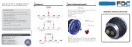
10b Codevalues10 2 09 188 167 146 125 1040830620410 2010b Codevalues1020918816714612510408306204102010 2 09 188 167 146 125 1040830620410 20010b Codevalues1020918816714612510408306204102010 2 09 188 167 146 125 1040830620410 200sinaCAMThe Menus9.2.5 Gamma & CM (Color Management)The Gamma & CM menu item defines the color space encoding that is applied to the output image. ThesinaCAM base unit comes with presets for Rec. 709 and S-Log gamma correction. It is possible to addcustomized gamma look-up tables (LUT) via the web interface (see chapter 10.2.5 Change Gamma LUT).Both legacy and extended color space output can be selected for every LUT.sinaCAM’s output values for legacy and extended color space adhere to the standard for HD video in10-bit systems as defined in SMPTE 274M.For legacy color space:64-940 for Y and 64-960 for Cb and Cr.For extended color space (called undershoot/overshoot in SMPTE 274M):4-1019 for YCbCr.Note that the difference between legacy and extended color space mainly affects how the resultingfootage has to be interpreted. A common misconception is that using extended color space provides ahigher dynamic range – this is not the case. The advantage is merely a slightly more exact color andbrightness gradation: 877 possible values (64 to 940) with legacy range versus 1016 possible values(4 to 1019) with extended range.Note: Extended color space is usually not displayed correctly on HD-SDI monitors,leading to clipped blacks and whites on the monitor, except on HD-SDI monitors thatexplicitly support extended color range signals.At the same time, legacy color space will most likely not be displayed correctly on DVI monitors, leadingto slightly grayish blacks and whites, unless the monitor is explicitly configured for legacy color spacesignals.Available default settings:R709LEG (gamma curve based on Rec. ITU-R BT.709, legacy color space)R709EXT (gamma curve based on Rec. ITU-R BT.709, extended color space)SlogLEG (gamma curve based on S-Log, legacy color space)SlogEXT (gamma curve based on S-Log, extended color space)<strong>User</strong>LEG (if uploaded by user – custom gamma curve, legacy color space)<strong>User</strong>EXT (if uploaded by user – custom gamma curve, extended color space)Figure 22: Rec. 709 vs. S-Log Gamma CurvesRec. 709Gamma Curve1020918816ASA/ISO 200 ASA/ISO 400 ASA/ISO 800714612510408306204102S-LogGamma Curve0014bit linear light space (lin)14bit linear light space (lin)14bit linear light space (lin)<strong>User</strong> <strong>Manual</strong> Rev.: D 29
The MenussinaCAM9.3 LEVEL MenuThis menu has white and black color level adjustment options for both remote heads. The white level isset individually for each head while the black level is set via one value with a second value setting thedifference between remote head 1 and 2.Figure 23: LEVEL Menu9.3.1 White LevelThe white level can be adjusted by using typical level adjustment tools, e.g., a test pattern with a series offive boxes ranging from dark gray to white with a pair of moving white bars on a white background. Thewhite level is correctly set when the right-hand white bar is barely visible.Available settings: White Level Head 1: −99 to +99 White Level Head 2: −99 to +999.3.2 Black LevelThe black level can be adjusted by using typical level adjustment tools, e.g., a test pattern with a numberof vertical black and gray bars that represent the various levels of black. The black level is set correctlywhen the very blackest bar disappears into the background.Available settings: Black level: −99 to +99– Head 1>2: −99 to +99 (difference between head 1 and 2)9.3.3 BBalance Red (Black Balance Red)Adjusts the red channel in relation to the black level setting.Available settings: BBalance Red: −99 to +999.3.4 BBalance Blue (Black Balance Blue)Adjusts the blue channel in relation to the black level setting.Available settings: BBalance Blue: −99 to +9930 Rev.: D <strong>User</strong> <strong>Manual</strong>
sinaCAMThe Menus9.4 MODE MenuThe Mode menu contains additional options for 2D and 3D recording.Figure 24: MODE Menu9.4.1 DVI-Mode9.4.1.1 CAM19.4.1.2 CAM2sinaCAM has a various number of digital monitor output possibilities at 60 Hz.Available settings:CAM1; CAM2; AltFrame; AltLine; Subtract; AnaglyphDVI monitor output of image from remote camera head 1DVI monitor output of image from remote camera head 29.4.1.3 AltFrame (Alternate Frame Sequencing)Alternate frame sequencing is a method of transmitting a 3D signal via a standard DVI connection.Images filmed with two remote camera heads are displayed in alternating order. The first left image isfollowed by the corresponding right image, then the next left image followed by the next right image andso on. This method requires LCD shutter glasses that can open and close the lenses for the left and righteye in rapid succession.9.4.1.4 AltLine (Alternate Line)9.4.1.5 Subtract9.4.1.6 AnaglyphAnother method of transmitting a 3D signal via a standard DVI connection. Line 1 is taken from theimage sent by camera head 1, line 2 from head 2, line 3 from head 1, line 4 from head 2 and so on. Theimages from both camera heads are displayed at the same time, but each at half vertical resolution. Thismethod is optimal for line-alternating polarized displays together with appropriate passive 3D glasses.This mode is used for exact calibration of two camera heads in 3D mode by determining the focal point.The image from camera head 1 is displayed in grayscale. The same goes for the image from camera head2, however this time the colors are inverted. When an object is focused on exactly by both camera heads,the object practically disappears on the monitor – all objects at approximately the same distance are thendisplayed correctly (without double images).Another method of transmitting a 3D signal via a standard DVI connection. The image from camera head1 is output in red, the image from head 2 in cyan. Viewing the resulting anaglyph image through red/cyanglasses will create a 3D effect.<strong>User</strong> <strong>Manual</strong> Rev.: D 31
The MenussinaCAM9.4.2 H-Flip (Horizontal Flip)In professional settings, 3D camera rigs often utilize two separate cameras or camera heads mounted ata 90° angle to each other. The incoming light is distributed between the two camera heads via a beamsplitter (a semi-transparent mirror). Such setups make it necessary to flip the incoming image for one oreven both of the cameras horizontally.Available settings:None; CAM1; CAM2; Both9.4.2.1 NoneNo horizontal flip is performed.9.4.2.2 CAM1Image from remote camera head 1 is flipped horizontally.9.4.2.3 CAM2Image from remote camera head 2 is flipped horizontally.9.4.2.4 BothImage from both remote camera heads is flipped horizontally.9.4.3 GenLockGenLock is used to synchronize multiple cameras to ensure that all cameras in a synchronization chainbegin reading the first pixel of an image from the sensor at the same time. The system needs a clockingcomponent that provides the synchronization data – currently, sinaCAM cannot provide a clock itself.Multiple sinaCAMs can be daisy-chained. The last camera in a chain must terminate the signal.Supported output formats: 720p60; 720p59.94; 720p50; 720p30; 720p29.97; 720p25; 720p24; 720p23.98 1080i60; 1080i59.94; 1080i251080p60; 1080p59.94; 1080p50; 1080p48; 1080p30; 1080psf30; 1080p29.97; 1080psf29.97;1080p25; 1080psf25; 1080p24; 1080psf24; 1080p23.98; 1080psf23.98Available settings:Free Run; Slv+Term; SlvChain; ExpTrgIn32 Rev.: D <strong>User</strong> <strong>Manual</strong>
sinaCAMThe MenusFigure 25: GenLock Example Setup with two sinaCAM Base Units and their Settings9.4.3.1 FreeRun (Free Run)The camera doesn’t synchronize with any signal. Even if it should receive sync data, it will run on its ownclock completely free from any synchronization.9.4.3.2 Slv+Term (Slave+Terminating)The camera is last in a synchronization chain and terminates the signal.9.4.3.3 SlvChain (Slave Chain)The camera is in the middle of a synchronization chain. It syncs itself to the signal and forwards the syncsignal to subsequent devices.9.4.3.4 ExpTrgIn (Exposure Trigger In)The Exposure Trigger In option enables providing an external trigger signal via the camera’s AUXterminal. "Falling edge" triggers exposure of the sensor while "rising edge" triggers the reading of sensordata.Note: The Shutter setting is ignored when this GenLock mode is active. The HD-SDI output is not insync with the exposure trigger signal!<strong>User</strong> <strong>Manual</strong> Rev.: D 33
The MenussinaCAM9.4.4 SharpenThis option sets the amount of sharpening applied to the image.Available settings:0 to 99Figure 26: MTF Graph for Sharpening FunctionExample values: 0, 10, 20 … 80, 90 (red curves) and 99 (green curve).34 Rev.: D <strong>User</strong> <strong>Manual</strong>
sinaCAMThe Menus9.5 SYSTEM MenuThis menu provides information about the system, such as IP address, date & time, software and firmwareversion. Two submenus provide access to some advanced system settings and allow software/firmwareupdates via USB. Additionally, the system’s factory settings can be restored.Figure 27: SYSTEM MenuMenu items:Service– Brings up the SERVICE menu.USB– Brings up the USB menu.Displayed system information in SYSTEM menu:IP address (used for web interface)Date & time (set via web interface) For more system info, push the arrow button below INFO.The INFO screen opens.9.5.1 INFO ScreenFigure 28: INFO ScreenDisplayed system information in INFO screen:Available internal memorySoftware version of the base unitFirmware version of the base unit Firmware version of remote head 1 Firmware version of remote head 2<strong>User</strong> <strong>Manual</strong> Rev.: D 35
The MenussinaCAM9.5.2 SERVICE MenuFigure 29: SERVICE MenuMenu items:Factory Preset– Select “Factory Preset” and push the scroll wheel to return the sinaCAM to its factory settings..Head Bars– Activates test bars generated by the camera heads (current image settings apply).Base BarsActivates test bars generated by the base station (image settings are without effect). The basebars output to HD-SDI terminals 1A/1B are slightly different from those for 2A/2B, with the1A/1B outputs displaying a white rectangular on the left, see figure below (it is gray for 2A/2B).Note: The Base Bars test image is not output via DVI!Figure 30: Base Bars test image with camera head 1/2 indicator field highlightedAutoHeadPwr– ON = By default, the base station automatically detects if a remote camera head is connected andactivates its 18V power supply (via the camera head coax cable) accordingly.– OFF = Auto detection is disabled, the 18V head power supply is forced into “always on” mode.NOTICEDo not connect any equipment other than sinaCAM camera heads to the remote head terminals whileAutoHeadPwr is set to “OFF”. The 18V supply voltage on these interfaces can damage the equipment!Displayed system information in SERVICE menu:Fan State– Indicates the status of the base station’s internal fans36 Rev.: D <strong>User</strong> <strong>Manual</strong>
sinaCAMThe Menus9.5.3 USB MenuFigure 31: USB MenuWhile in this menu, you can manually trigger a frame grab to a connected USB stick by pressing F2.Menu items:Auto Grab– By default, the sinaCAM initiates a frame grab every time a USB stick is connected (see chapter8.5, Frame Grabbing to USB Storage Device). If necessary, this can be disabled by setting AutoGrab to OFF.Update– Only shown when a USB stick with an update package is connected to the sinaCAM’s USB port.Select “Update” and push the scroll wheel to start the software/firmware update process.Note: Supported file systems are FAT32, ext2 and UDF (no NTFS!). The update package must be inthe USB stick’s root directory. Make sure there is only one package on the USB stick, otherwise it isnot guaranteed that the most recent one will be installed.<strong>User</strong> <strong>Manual</strong> Rev.: D 37
The Web InterfacesinaCAM10. The Web Interface10.1 Getting Started10.1.1 Required Tools1. PC with one available Ethernet port or a local Ethernet connection2. Web browser3. sinaCAM update package (e.g., SinaCam_1.0_1575.pkg)Note: The latest firm- and software updates can be downloaded from: www.sinacam.eu/support/10.1.2 Connecting to sinaCAM Start the web browser. Use an Ethernet cable to connect the sinaCAM to the PC itself or to the local Ethernet network thePC is operating in. Make sure one of the following are supported:– DHCP– Zero configuration networking for ad-hoc networking Switch on the sinaCAM. Look up the sinaCAM IP address in the sinaCAM menu SYSTEM. Crosscheck the IP addresses of sinaCAM vs. PC Both shall be in the same subnet. Enter the sinaCAM IP address into the web browser’s address field. Log in with the username eddy and the password 99999999.Figure 32: Web Manager - Login38 Rev.: D <strong>User</strong> <strong>Manual</strong>
sinaCAMThe Web Interface10.2 Setup Menu10.2.1 SummaryFigure 33: Web Manager - SummaryThis menu screen gives an overview of the current system configuration and some additional information.10.2.2 Network SettingsNOTICEChanging and/or disabling of network settings can lead to a lock out from sinaCAM’s webconfiguration feature. Make sure not to unintentionally change any settings.<strong>User</strong> <strong>Manual</strong> Rev.: D 39
The Web InterfacesinaCAMFigure 34: Web Manager - Network SettingsHere you can change the network settings of the sinaCAM.10.2.3 Wireless SettingsNote: The Wireless Settings menu is only available if the optional available WLAN module for thesinaCAM is installed. Without WLAN module, this menu has no effect.10.2.4 Date & TimeFigure 35: Web Manager - Clock AdjustHere you can set the sinaCAM’s system date and time.40 Rev.: D <strong>User</strong> <strong>Manual</strong>
sinaCAMThe Web Interface10.2.5 Change Gamma LUTFigure 36: Web Manager - Update Gamma LUTIn addition to the factory preset gamma look-up tables (LUTs), the sinaCAM can beconfigured with custom LUTs.Note: At this point there is no feedback if a faulty LUT file is uploaded.10.2.5.1 Naming <strong>User</strong> LUTsRegardless of the LUT file’s name, the gamma settings contained therein will be select-able as USER inthe sinaCAM menu. Thus, only one user setting can be stored on the sinaCAM using the regular uploadmethod, as uploading a new user LUT overwritesthe previous USER settings.However, if the LUT is put into a tar archive, uploading that archive to the sinaCAMwill create a new user setting with the name of the LUT file within the archive. It is also possible toupload several LUTs at once by placing them within the same archive. Supported compression methodsfor the archive file are xz, lszma, bz2 and gz.10.2.5.2 Gamma LUT File FormatA LUT file, as supported by the sinaCAM, is a text file with no header. It contains 16384 hex values,assigning one to each of the 16384 (14-bit) possible input values from the camera head’s sensor. Thevalues are given in text form (without a preceding "0x"!), separated by any whitespace character(including line breaks), and can range from 0 to FFF, thus mapping the 14-bit input values to a12-bit format.<strong>User</strong> <strong>Manual</strong> Rev.: D 41
The Web InterfacesinaCAM10.3 Updating the FirmwareFigure 37: Web Manager – Update Firmware Go to the Update Firmware menu. Browse and select the .pkg file to upload. Push Start Update.The upload should take about a minute, after which the following screen should appear:Figure 38: Web Manager – Firmware Now UpdatingAfter a while, a blank screen should appear – the system is booting. The Ethernet connection isterminated at this point. Check the firmware version displayed in the local sinaCAM menu SYSTEM INFO. Reset the sinaCAM to its original settings via the Factory Preset command in the sinaCAM’s localSYSTEM menu. If everything was successful, switch the power off and on again for a final test.42 Rev.: D <strong>User</strong> <strong>Manual</strong>
sinaCAMRemote Head System LED Indications11. Remote Head System LED IndicationsTable 7: Remote Head System LED IndicationsNo powerSystem bootingStateLink detection in progress, power supply for remotecamera head activeLink detection in progress, resyncPower supply for remote camera head over-current(Host only)Device / Host connected, but no data being transferredDevice / Host connected, data being transferredError during data transfer (e.g., CRC error, singlebit error detected)System error (e.g., internal error)OffSolid orangeFast flash greenIndicationShown for a minimum of 1 s even if the linkdetection is fasterFast flash orangeShown for a minimum of 1 s even if the linkdetection is fasterSolid redSlow pulse greenSolid green whenever data transferred (i.e.blinks synchronously with data)500 ms red pulseIn case of multiple errors, there shall be at least200 ms green before the next error is indicatedFast flash red<strong>User</strong> <strong>Manual</strong> Rev.: D 43
MeasurementssinaCAM12. Measurements(all measurements in mm)Figure 39: Base Unit MeasurementsFigure 40: Remote Camera Head Measurements44 Rev.: D <strong>User</strong> <strong>Manual</strong>
sinaCAMTechnical Specifications13. Technical SpecificationsTable 8: Technical Specifications – Remote Camera Head HDC1-100Image SensorSensitivityResolutionDynamic RangeSignal/Noise RatioInterfaceMax. Cable LengthsLens MountPower ConsumptionOperating Temperature RangeRemote Camera Head HDC1-1002/3” Single Chip Kodak CCD Sensor (RGB)2004×1144 Pixels, Progressive Scan2000 Lux @ f 8.0 / 0 dB Gain (100 % video out)160 Lux @ f 2.2 / 0 dB Gain (100 % video out)1920×1080 Pixels13.5 f-stops64 dB @ 0 dB GainCoaXPress, 75 Ω BNC Cable80 m (260 ft) with Standard BNC Cable180 m (590 ft) with Gepco VHD1100 Cable (Option)C-mount with Flange Back Distance adjustment4.6 W max.0 to 45 °C (32 to 113 °F)Table 9: Technical Specifications – Base Unit HDC1-200Digital Signal ProcessingWhite Balance ModesBlack LevelExposure ControlGammaElectronic ShutterRemote Head ConnectionsBase Unit HDC1-200Single Chip DSP (dual 14-bit)AWB: Automatic White Balance (Push to set White Balance)3200 K, 4300 K, 5600 K, 6500 KMAN: <strong>Manual</strong> White Balance (red and blue adjust)adjustable200, 400, 800 ASARec. 709, S-Log, custom via web interfaceFull Frame, 1/50 s to 1/5000 sCoaXPress (via 75 Ω BNC Cable)Output Signals up to 4× HD-SDI (SMPTE 292M, 372M)DVI (Digital Monitor Output 1920×1080 @ 60 Hz)HD-SDI Video FormatsYCbCr 4:2:2 / 10 bit1920×1080 / 24p, 24psf, 25p, 25psf, 50i, 30p, 30psf, 60i,48pDL*, 50pDL*, 60pDL*, 23.98p, 23.98psf, 29.97p, 29.97psf,59.94i, 59.94pDL** = HD-SDI Dual-Link Mode3D MonitoringSynchronizationWith May 2012 firmware update:1280×720 / 24p, 25p, 30p, 50p, 60p, 23.98p, 29.97p, 59.94pCAM1, CAM2, Alternate Frame, Alternate Line,Subtract, AnaglyphInternal or GenLock to Tri-Level Sync or Black Burst<strong>User</strong> <strong>Manual</strong> Rev.: D 45
Technical SpecificationssinaCAMRemote Control Panel SupportBase Unit HDC1-200With July 2012 firmware update:Sony RCPs that use the 700 Protocol can be connected via the AUXterminal, for example:Sony MSU-700/700A/750/900/1000/1500Sony RCP-700/701/720/721/730/731/740/741/750/751/920/921/1000/1001/1500/1501/1530Sony RM-B150/B750Supported features: Master Black setting 1 Master White setting 1 Master Gain setting (-6 to +12 dB) Shutter setting 5600K (electronic color temperature conversion) on/off PsF (CCD progressive read function) on/off Auto White Balance Step Gamma setting: 0.40 (BBC) or 0.45 (Rec. 709) Gamma setting 1 Knee Point setting 1 Knee Slope setting 1 Black Gamma setting 1 , Low/L Mid/H Mid/High range setting White Clip setting 1 Detail 1 Level setting (sharpening) "Test" button enables output of a test pattern(generated at camera heads, image processing with currentsettings is applied) "Bars" button enables output of SMPTe color bars(generated at base station, no image processing)1 Master setting and separate R/G/B settingsCommunication Ports 100 MBit Ethernet, USB 2.0, RS-232 / 485<strong>User</strong> InterfaceGraphical <strong>User</strong> Interface, Web Interface10-Pin AUX TerminalRS-232 / 485, Iris Control, Exposure Trigger I/O, Timecode I/O2-Pin Power Terminal12 to 24 V DCPower Consumption30 W max. (incl. two Remote Camera Heads)Operating Temperature Range 0 to 45 °C (32 to 113 °F)46 Rev.: D <strong>User</strong> <strong>Manual</strong>