2N EntryCom User Manual - Came UK
2N EntryCom User Manual - Came UK
2N EntryCom User Manual - Came UK
- No tags were found...

Create successful ePaper yourself
Turn your PDF publications into a flip-book with our unique Google optimized e-Paper software.
<strong>2N</strong> ® <strong>EntryCom</strong>Door Entry System<strong>User</strong> and Service <strong>Manual</strong>Version 2.0
Dear customer,We congratulate you on having purchased the <strong>2N</strong> ® EnrtyCom doorcommunicator, which is the successor to the popular product <strong>2N</strong> ® - ENTRYCOM V1. Wehope you will fully enjoy using this new product for a long time to come.Merits of the Product1. Exclusive design, – high-grade stainless steel finish.2. Slim line design – no cutting into a supporting wall is required.3. Exclusive long-life white illumination – LEDs.4. New waterproof design.5. Buttons have no mechanical parts – long service life.6. Up to 16 buttons per unit.7. Optional equipment – camera, display, etc.8. Increased protection through Vandal Resistant panel.9. Electronic volume and Handsfree control – no need to open the cover.10. Ringing tone detection – hangs up automatically after a defined amount of rings.11. Voice menu based programming.Version ChangesList of <strong>Manual</strong>/Product Changes2.0 A new version of the communicator firmware released in April 2007.Marking: FW:07-02-22• New voice functions – new parameters 974, 976 and 977• Double-tone detection• New implicit value of parameter 951• Antivandal assortment upgraded2
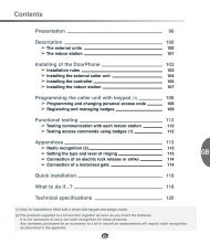
1. FEATURES .................................................................................................. 41.1. OPTIONAL ACCESSORIES: .............................................................................................................. 42. PURPOSE.................................................................................................... 53. PRODUCT MIX ............................................................................................. 63.1. BASIC AND EXTENDER UNITS ......................................................................................................... 63.2. INSTALLATION ACCESSORIES ......................................................................................................... 73.3. INCREASED PROTECTION ACCESSORIES......................................................................................... 83.4. GSM AD VOIP CONNECTION ACCESSORIES.................................................................................... 83.5. DISPLAY........................................................................................................................................ 83.6. VIDEO ACCESSORIES..................................................................................................................... 93.7. ELECTRIC LOCKS........................................................................................................................... 93.8. OTHER ACCESSORIES.................................................................................................................... 94. TERMINOLOGY.......................................................................................... 105. FUNCTION DESCRIPTION .......................................................................... 115.1. FROM EXTERNAL USER'S VIEW (VISITOR)..................................................................................... 115.2. FUNCTION DESCRIPTION – NUMERICAL KEYPAD UNITS.................................................................. 115.3. FROM INTERNAL USER'S VIEW (SURVEY OF FUNCTIONS)............................................................... 125.4. SIGNALS OVERVIEW .................................................................................................................... 135.5. MESSAGE OVERVIEW ................................................................................................................... 135.6. CALL TERMINATION OPTIONS - SUMMARY ..................................................................................... 145.7. CODE LOCK ................................................................................................................................ 145.8. TRADITIONAL BUTTON TELEPHONE............................................................................................... 145.9. DTMF TRANSMISSION DURING OUTGOING CALL ........................................................................... 155.10. BUTTONS SUBSTITUTION.............................................................................................................. 155.11. KEYPAD OPERATION INSTRUCTIONS - SUMMARY ........................................................................... 156. INSTALLATION INSTRUCTIONS.................................................................. 186.1. START UP ................................................................................................................................... 186.2. MECHANICAL MOUNTING.............................................................................................................. 186.3. BUTTONS LABELS – INSERTION, REPLACEMENT ............................................................................ 207. ELECTRICAL INSTALLATION ..................................................................... 217.1. COMMON INSTALATION ................................................................................................................ 237.2. CAMERA INSTALLATION................................................................................................................ 277.3. DISPLAY INSTALLATION ................................................................................................................ 277.4. CONNECTION OF EXTENDER UNITS............................................................................................... 288. PROGRAMMING......................................................................................... 319. FULL PARAMETER CHART......................................................................... 3410. MAINTENANCE.......................................................................................... 3811. SECTION FOR ADVANCED USERS.............................................................. 3811.1. AUTOMATIC MULTIPLE NUMBER DIALLING ..................................................................................... 3811.2. ARRIVAL/DEPARTURE, DAY/NIGHT MODES ................................................................................... 4112. TECHNICAL PARAMETERS ........................................................................ 4212.1. TELEPHONE PARAMETERS ........................................................................................................... 4212.2. OTHER PARAMETERS................................................................................................................... 423
1. Features• Operates on any analogue telephone line• Telephone-controlled electronic lock switch• Exclusive white button backlight – white LEDs• Modularity – up to 54 buttons + keypad• Applicable as a standard telephone and code lock (keypad version)• Flat design – installation no need to cut into mounting surface• Water resistant:• Hermetically sealed buttons• Separate electronics from name plates• Telephone-based programming• Detection of all standard tones• Stable line power feeding• High acoustic quality• Electronic volume and Handsfree control – no need to open cover• Special functions includes automatic dialling of multiple numbers, silentdialling, departure/arrival, day/night mode, second switch delay1.1. Optional Accessories:• Vandal resistant panel• New resistant metal cover for better protection against vandalism.• Flush mounting steel box included in the cover price.• Can be purchased and installed as an option.• Additional (second) switch• With switching and breaking contact (relay).• Time-unlimited switch option.• <strong>Came</strong>ra unit• Can be installed into any basic unit (incl. Vandal Resistant).• High-quality colour CCD.• Wide angle, adjustable direction.• Proximity reader unit – can be installed into the basic unit as an option.• Display module• Can be installed into any basic unit as an option.• Graphic LCD, backlight with automatic brightness regulation.• Up to 1,000 characters including text and graphics.• PC configuration, USB interface.4
2. PurposeThe <strong>2N</strong> ® - <strong>EntryCom</strong> door communicator replaces a traditional door entry systemwhich would traditionally have to have a whole cabled distribution infrastructure behindit. The connectivity of the unit is flexible in that as standard the unit can connect to anytelephone system via either an analogue extension or trunk port. The <strong>EntryCom</strong> unit canalso connect to any network provider’s analogue telephone line.<strong>2N</strong> ® - <strong>EntryCom</strong> is also easy to use – just press the desired call button and the<strong>EntryCom</strong> unit will automatically “dial“ the number pre-stored in the respectivememory. The number of buttons is flexible as it is a modular unit.<strong>2N</strong> ® - <strong>EntryCom</strong> also has a switch that controls the electric lock by using anytelephones keypad (by tone-dialling the password).In addition to the buttons, you can use a numerical keypad, which is used as a codelock. Using the keypad, you can operate the device as a button telephone and dial therequired numbers directly or retrieve them from any of the 54 memories available. Youcan disable non-desired functions.<strong>2N</strong> ® - <strong>EntryCom</strong> provides improved and feature rich options compared with standarddoor entry systems, this is because you can make use of functions such as callredirection if not answered, or have a day and night mode set up for automaticredirection of the call for instance after normal working hours.The <strong>2N</strong> ® - <strong>EntryCom</strong> parameters meet all technical requirements mandatory fordevices designed for the PSTN (public switched telephone network) connection.5
3. Product Mix3.1. Basic and Extender UnitsPart No. 9135130EBasic unit3 buttonsPart No. 9135130KEBasic unit3 buttons + keypadPart No. 9135181EExtender unit8 buttonsPart No. 9135160EBasic unit3x2 buttonsPart No. 9135160KEBasic unit3x2 buttons + keypadPart No. 913582EExtender unit8x2 buttonsPart No. 9135310EInfo panelA backlit buttonless panel used for thetelephone directory, house number, etc.Part No. 9135311EInfo panel – name plateReplaces four name plates with one cover.Enables the use of one half of theextender unit for the telephone directory,opening hours, etc.Part No. 9135320EInfo panel + 4 bell buttonsAn independent product not connected tothe telephone line. Combines four bellbuttons and space for the company ordepartment name, opening hours, etc.All the above-mentioned units can be wall mounted without requiring any additional accessories.All the basic units can be complemented with a camera, proximity reader (see later) and display(under preparation). All units can be made more resistant using the Vandal resistant cover.Additional accessories (see later) are needed for outdoor flush mounting purposes.6
3.2. Installation AccessoriesPart No. 9135331EWall mounting rooffor 1 moduleDimensions (WxHxD):103 x 218 x 60 mmPart No. 9135351EFlush mounting boxwith 1-module frameDimensions:125 x 235 x 46 mmHole:110 x 220 x 50+- 5 mmPart No. 9135361EFlush mounting box with 1-module roofRoof dimensions (WxHxD) :129 x 240 x 41 mmHole (WxHxD):110 x 220 x 50mm +- 5mmPart No. 9135332EWall mounting rooffor 2 modulesDimensions (WxHxD):203 x 218 x 60 mmPart No. 9135352EFlush mounting boxwith 2-module frameDimensions:225 x 235 x 46 mmHole:210 x 220 x 50+- 5 mmPart No. 9135362EFlush mounting box with 2-module roofRoof dimensions (WxHxD) :229 x 240 x 41 mmHole (WxHxD):210 x 220 x 50mm +- 5mmAll mounting accessories are made from stainless steel particularly necessary foroutdoor applications unless there is suitable weather protection. The flush mountingframe box (without roof) enables installation of the <strong>EntryCom</strong> unit indoors so that itdoes not protrude from the wall (up to 1 mm).7
3.3. Increased Protection AccessoriesPart No. 9135511EVandal resistant cover for basicunit + Flush mounting box *)Part No. 9135511KEVandal resistant cover forbasic unit with keypad + Flushmounting box *)Part No. 9135515EVandal resistant cover for oneextension unit + Flushmounting box *)*) Attention! This box is not 9135351E !!! It is a special box only for Vandal resistant covers.The purpose of the covers shown above is to make the basic units or sets with up to 11buttons as weather and vandal resistant as possible. More extensive sets can be tailormade.Remember that the Vandal resistant set must always be flush mounted andneeds no roof even if used outdoors.3.4. GSM ad VOIP connection accessoriesGSM gateway Easygate,501303EAnalog/VoIP gateway,Part No. 9134171E3.5. DisplayBlack & white, Graphic LCD 128 x 64 pixels,white backlight, up to 1000 characters,configurable via USB interface, can beinstalled into any basic unit as an option.Part No. 91352408
3.6. Video AccessoriesPart No. 9135210EIn-built colour CCD cameraPAL, resolution 420 TV rows, sensitivity 2 luxThe camera can be built in any basic unit. Inthe case of poor light, the camera switchesinto the monochrome mode automatically.Supplementary infrared light.Horizontal/vertical tilting option.3.7. Electric LocksPart No. 9134147E7" colour LCD monitor (TFT)The selected model features acomposite video signal input with highsensitivity for long cabling runs. Vividcolours, wide-angle display option, inbuiltTV set. The right to change thedesign is reserved.Part No. 9134145EMPEG4 LAN video serverVideo records can be observed byanybodies PC via the LAN, no SWinstallation is needed. Serves up to 10 PCsat the same time. The MPEG-4compression ensures the network load isapproximately 10 times lower thanuncompressed. The Internet can also beused to watch the video.. Quality / dataflow control option. Free SW for intelligentrecording of the video record into a PC(includes movement detection).Part No. 932070EBEFO 1211 12V / 600 mAPart No. 932080EBEFO 1221with torque pinPart No. 932090EBEFO 1211MBwith mechanical blocking3.8. Other AccessoriesPart No. 9135250EAdditional switchSwitching and breaking contact option,time-unlimited switching, up to 48 V / 2A.Part No. 91341481E12V / 2A adapterA stabilised power supply must be used ifa camera is installed. It can also feed thelock and backlight.Part No. 9134148ESIEMENS ® adapterThis is required when connecting to aSiemens HiPath Telephone systemPart No. 932928E12V TransformerPart No. 9135301Ename platePart No. 9135302Edouble-button name plate9
4. TerminologyLine pick-up/seizure/off-hook – call start, line locked, busy.Line hang-up/clear – call end, handset hang-up.DTMF – dual tone multi-frequency signalling.PSTN – public switched telephone network.Outgoing call – <strong>EntryCom</strong>-telephone connection made, e.g. by a pressing a button.Incoming call – telephone-<strong>EntryCom</strong> connection.Programming mode – <strong>EntryCom</strong> programming mode accessible from by dialling intothe intercom only.Code lock – mode for entering the password for switch 1 or 2 activation using anumerical keypad.Telephone mode – you can make a call, dial a number and hang up using thenumerical keypad.DTMF transmission during call – for outgoing calls only, numbers are tone-dialled bya numerical keypad button.Button substitution – the numerical keypad can be used instead of a number prestoredunder a button memory.10
5. Function Description5.1. From External <strong>User</strong>'s View (Visitor)Like normal Doorbells, <strong>EntryCom</strong> buttons are provided with labels the visitor finds theappropriate button (e.g. Mr. Smith) and presses it this activates <strong>EntryCom</strong> to then dialthe number pre-programmed for under that button, the visitor can then hear the ringingtone from the loudspeaker and the required (Mr. Smith‘s in this case) telephone isringing. If the <strong>EntryCom</strong> unit is connected to a telephone system you may be able to tagthe port that <strong>EntryCom</strong> is connected to so that you can see on the ringing phone that itis the <strong>EntryCom</strong> that is calling. When the called party answers the call, the visitor andtenant can speak to each other and If an electric lock is connected to <strong>EntryCom</strong>, thecalled person can open the door by entering the correct password on the telephonekeypad to activate the door or barrier. When the caller hangs up, <strong>EntryCom</strong> detects thePBX or analogue line tone and hangs up too. <strong>EntryCom</strong> also hangs up when it “hears”the busy tone or if the call takes more time than pre-programmed to connect. You canpre-program the amount of time that you have to speak into the microphone howeverwhen you are reaching the programmed time the unit gives a warning tone 10 secondsbefore hanging up so that the called party can extend the call if required.Notes:• If the visitor presses another button during the call, <strong>EntryCom</strong> hangs up for a fewseconds before dialling the new number.• If a button is pressed that has no number stored within it <strong>EntryCom</strong> picks up theline, sends a refusal tone (refer to the Signals Overview) and hangs up.• If the visitor presses the same button during the call, <strong>EntryCom</strong> may hang up (canbe programmed to stop this feature if required).• The above mentioned rules are only applied if the Automatic Multiple NumberDialling mode is OFF. For this special mode refer to the Automatic Multiple NumberDialling section.5.2. Function Description – Numerical Keypad UnitsThe 2ENTRY ® - <strong>EntryCom</strong> basic units, Part Nos. 9135130K and 9135160K, areequipped with a numerical keypad. The keypad provides a number of functions:• traditional code lock• features as if a normal telephone set• DTMF transmission during an outgoing call• substitution of up to 54 buttonsThe keypad features a smart metal design and very favourable price to performanceratio. For the description of the functions from the user‘s view see below.11
5.3. From Internal <strong>User</strong>'s View (Survey of Functions)• Calling to <strong>EntryCom</strong>You call the appropriate extension and <strong>EntryCom</strong> makes the call and gives aconfirmation tone after two rings (or as pre-programmed). Now you can speak andcontrol the 2 switches, program <strong>EntryCom</strong> (see later), and listen to what is going onoutside and speak to the calling party if desired..• Opening door<strong>EntryCom</strong> contains a switch to which an electric lock can be connected (notincluded in this pack). This switch can be telephone keypad controlled using a(digital) password in two ways as shown in the default password 00 example below:orThe switch activation time can be programmed once the switch is enabled thiswill also automatically terminate the call in the next 30 seconds.Notes:• If the Automatic Multiple Number Dialling with Confirmation or the Silent AutomaticMultiple Number Dialling with Confirmation mode is selected and the passwordstarts with digits 1 to 5, an asterisk must always be used.• You Must enter every digit in the password within five seconds (or as preprogrammed)to avoid <strong>EntryCom</strong> from hanging up.• Switch 2 activation (light, e.g.):The second switch (if an additional switch is installed) can be controlled in the sameway.• Switch 2 synchronisation:Switch 2 can also be used to delay the opening of another door. Once the switch 2delay timeout is programmed, the second switch is synchronised automatically withthe first one, the delay being 1 – 25 seconds.• Switch activation signalling (for both switches)After the correct password is entered, the switch is activated and you can hear theconfirmation signal on your telephone. You can now speak (e.g. say: “The door isopen“) or listen (to the door-opening sound, etc.) until the switch is deactivated.Upon deactivation, you can hear the storing signal (see the Signals Overview).• Call extension<strong>EntryCom</strong> beeps 10 seconds before the call end to extend the call by 30 secondspress on your telephone (DTMF). You can use this function repeatedly. Thevisitor, however, cannot use this function!• ProgrammingThe access to this mode is password-protected. For details refer to theProgramming section. The voice menu considerably helps with programming the<strong>EntryCom</strong> unit. Having entered the programming mode, you can also alter anyparameter and memory settings.Caution: The above mentioned functions (except for calls to <strong>EntryCom</strong>) require atone-dialling telephone set.12
5.4. Signals OverviewSignal Name MeaningConfirmationRefusalLong continuoustone• sent immediately after line seizure for incoming calls (can beheard by the calling party);• signals switch activation (by DTMF) - can be heard by theperson “at the other end“ who activated the switch• signals that a non-programmed button has been pressed;• signals that an incorrect password has been entered on thekeypad;• can be heard from the loudspeaker after line connection (firstconnection signalling);• signals an incoming call if <strong>EntryCom</strong> has not beenprogrammed;• When a disabled function has been entered from the keypad.Storing • Signals switch deactivation (if activated by DTMF).Hang-up • Sent to notify that the call is terminated (in all cases).• signals that the unit is going through full initialisation or diallingmemory or password clearing;• Heard from the loudspeaker while the switch is activated bykeypad.“Attention, your callis being terminated”signals that the preset maximum call time will elapse within 10seconds during outgoing and incoming calls“Wait, please“ • Optional message during call establishing“Communicatornumber ............... • Optional message for communicator identificationis calling”Voice menu In the programming mode.5.5. Message overviewParametervalue976, 977Languageorder – CzechversionMessage about a callterminationMessage about a call establishing0 original signal Switched off !!!Attention, your call isCommunicator number...... is1*) EnglishWait, pleasebeing terminatedcalling2 Czech Pozor, končí hovor Čekejte, prosímVolá komunikátorčíslo ........3 Slovak ................... ................... ...................4 German ................... ................... ...................5 Russian ................... ................... ...................6 Polish ................... ................... ...................7 Slovenian ................... ................... ...................8 Portuguese ................... ................... ...................*) Initial value. ATTENTION – Czech version of the product has Czech language under number 1 andEnglish is under number 2!13
5.6. Call Termination Options - Summary1. The busy or continuous tone *) after the call end.2. The ringing tone *) after a predefined count of rings.3. The subscriber “at the other end“ pressed .4. The preset maximum call duration has elapsed.5. 30 seconds after the switch use has elapsed.6. A <strong>EntryCom</strong> button was pressed during the call.7. The keypad button was pressed during the call (can be disabled).*) The communicator is able to detect a permanent tone, busy tone and ringing toneeven if the tone has two frequency components as in the <strong>UK</strong>, the U.S.A. (the so-calledBTT tone) and in Canada. This new function does not require setting of any parameter.One of the tone components must be of 440 Hz.5.7. Code LockThe electronic lock connected to the <strong>EntryCom</strong> can not only be activated by thephone but also directly from the door using the keypad. In this mode, the keypadbehaves like a standard code lock with the following features:• Both switches can be controlled (if 2 connected)• Password length - 1 to 16 digits;• Up to 10 passwords per switch;• Switch activation time - 1 to 9 seconds;• Acoustic switch activation signalling – continuous tone.The code lock uses the same passwords as the ones that have been defined for thetelephone based switch control. Remember that the default passwords (00 for switch 1and 11 for switch 2) cannot be entered from the numerical keypad because they arenotoriously known.ControlEnter the correct password and . If the password is valid, a long tone istransmitted for a predefined time (5seconds by default). The corresponding switch isactivated during this time. If the password is invalid, <strong>EntryCom</strong> sends a refusal signal.5.8. Traditional Button TelephoneAny number can be “dialled” in this mode. To dial, press , and to hang up use .These keys are typically provided with pictograms and . PSTN calls can bebarred for a line in the PBX. The dialling type (tone, pulse) is selected in theprogramming mode. With pulse dialling, the character initiates (upon off-hook)transition to tone dialling – like on any other telephone.Note: If this function is enabled, you can press to hang up an outgoing call initiatedby pressing a separate button.14
5.9. DTMF Transmission during Outgoing CallThis function enables the unit to transmit DTMF tones when the connection with oneof the pre-programmed numbers has been established. It is used in combination withautomatic information systems, voice mailboxes, etc., which ask the calling party toselect a service using tone dialling. This function, however, does not allow you to calldestinations other than the pre-programmed ones.5.10. Buttons SubstitutionThis function is an analogy to memories in comfortable telephone sets. After twodigits ranging between 01 and 54 (0 may not be omitted) are pressed, the call to thepre-programmed number is made. You can use <strong>EntryCom</strong> as if it had up to 54 separatebuttons, which saves buying the extender units and space on the installations wall. Theideal solution is to use a few standard buttons for the most important speed diallingoptions e.g. Warden, Reception and then provide a list of pre-programmed options viathe optional info panel that can be purchased.Admissible Keypad Function CombinationsAll of the above mentioned 4 functions can be combined freely – each of them can beenabled or disabled separately as desired.5.11. Keypad Operation Instructions - Summary• Door opening – code lockEnter any valid password for switch 1 and .Warning! Password 00 may not be used!• Switch 2 activation:Enter any valid password for switch 2 and .Warning! Password 11 may not be used!• Traditional button telephonegets <strong>EntryCom</strong> ready to dial a number.… Dials a number.Transmits into tone dialling during pulse dialling.Transmits a character in tone dialling.Hangs up anytime during a call.• DTMF transmission during outgoing call( of a single button, not in the telephone mode!)… - tone-dials a number.- The character is sent normally.- The character is sent normally.• Buttons substitution:01…54 – the number that complies with the selected button (memory) is dialledafter a timeout.- If an asterisk is pressed after number 01…54, the number is dialledimmediately unless it is identical with the set password.15
Frequently Asked Questions Regarding Keypad Function• Can any of the switches be activated permanently?Yes, the additional switch can be activated by one password and deactivated byanother.• Is it possible to arrange for the switch to be activated during the whole call?Yes, additional switch can do it.• Is it possible to use a single command to activate one switch first and theother later?Yes, it is possible to use parameter 824, Switch 2 delay.• Can both the switches be activated at the same time?While one switch is activated, the other can be activated by another password. Youcan also use parameter 824, Switch 2 delay, defining the shortest delay timepossible (1second) and a sufficiently long switch activation time.• Can I use the code lock while another person is speaking through <strong>EntryCom</strong>?Yes but this is not advisable as you should be aware that the password is privateand could contravene security.• What happens when I press a number with no pre-programmed memory whilethe button replacing function is enabled? The same as if you pressed a buttonthat is not pre-programmed: <strong>EntryCom</strong> seizes the line, beeps refusal (refer toSignalling) and hangs up immediately.• What happens if a password is identical with the memory number while thecode lock and button substituting functions are enabled? The code lockfunction has the highest priority. If, for example, the password is 33 and you press, the switch is activated instantaneously. If you press without an asterisk,the line is seized after a preset delay and the number from memory 33 is dialled.Password Selection TipsTip 1: Keyboard letters facilitate password remembering. For example, it is easier toremember a 9-letter word (e.g. crocodile) than a 9-digit number (276263453).Tip 2: It is not recommended to use such passwords as 3333. This leads to aconsiderable wear and tear of one button and an unauthorised person mayguess your password easily. It is ideal to employ all keys evenly, using severalcodes for different persons or groups.16
ENTRYCOM Statuses and Available OperationsHang-upOutgoing callIncoming callProgrammingTelephonemodeOperationButton pressing – new call --- --- Call extension - DTMF --- --- Call termination - DTMF --- Hang-up upon continuous, busy or ringing--- toneSwitch activation – DTMF password --- --- Programming start --- --- --- ---Switch activation – code lock 1) --- --- ---DTMF into outgoing call --- --- --- 2)Button replacing (speed dial from memory) 1) --- --- ---Off-hook by key (into telephone mode) --- --- --- ---KeypadHang-up by key --- 1) --- --- Hang-up by key --- 1) --- --- ---Explanatory notes:… Yes, always … Yes if this function is programmed1) This holds if DTMF is disabled during outgoing calls (the corresponding tone istransmitted in that case).2) If pulse dialling is selected, it is possible to switch into tone dialling by pressing(but not vice versa!).17
6. Installation Instructions6.1. Start UpPlease check the contents of your delivery:Basic unit1 pcThis manual1 pcInbus key 2/51 pcTransparent name plate foil of size A5 1 pcDowels2 pcsScrews2 pcsSubstitute name plate1 pcNote: If you have bought a complete “packet“, the delivery may contain additional itemsincluding instructions for use and lists of available parts.6.2. Mechanical MountingMounting OptionsWhat You Need for MountingIndoor wallmounting- <strong>2N</strong> ® <strong>EntryCom</strong> onlyIndoorflushmounting- <strong>2N</strong> ® <strong>EntryCom</strong>1-module flush mounting box withframe, Part No. 9135351E, or2-module flush mounting box withframe, Part No. 9135352EOutdoorwallmounting- <strong>2N</strong> ® <strong>EntryCom</strong>- 1-module wall-mounting roofPart No. 9135331E, or- 2-module wall-mounting roofPart No. 9135332EOutdoorflushmounting- <strong>2N</strong> ® <strong>EntryCom</strong>- 1-module flush mounting box with roofPart No. 9135361E, or- 2-module flush mounting box with roofPart No. 9135362EIncreasedProtection- <strong>2N</strong> ® <strong>EntryCom</strong>- Vandal Resistant cover with a boxdesigned according to the set to bemounted18
Explanatory Notes to the Table Above:For the purpose hereof, indoor environment means:• Interior space with low relative humidity, such as corridors, offices and otherenvironmentally controlled rooms.• Interior space where moisture condenses on walls but in no case flows downthe walls, such as verandas, storing rooms, industrial facilities.• Exterior space sheltered against rain and water flowing down the walls, suchas shelters, passageways.For the purpose hereof, outdoor environment means:Environment, where a product is exposed to rain and / or water flowing down thewalls, such as fences, external walls of buildings, etc.WARNING:The warranty does not cover failures and defects of the product arising asa result of improper installation (in conflict with these instructions). Inaddition, the manufacturer shall not be held liable for damage incurredthrough misappropriation from rooms that are accessible after the attachedelectric lock is activated. The product is not intended as an anti theft / entrydevice on its own only in combination with a classic safety lock.Wall Mounting1. Drill holes using the template,inserted in the manual. Use the walldowels attached.2. With multiple module sets, connect theframes as shown in the figure. Placethe basic unit on the left and extenderunits on the right. The interconnectingcable should be installed later!3. Put the blanking modules on theunused side holes as shown in thefigure.4. If you are utilising a roof module, youshould install it now.5. Screw <strong>EntryCom</strong> onto the wall. Carry the supplycables (line, lock, power supply) through one ofthe holes into the basic unit frame.6. If you use a roof module, fix its upper and sideedges to the wall using silicone as shown in thefigure.Silicone19
Keep the following outdoor mounting principles:• Connect the button backlight for equipment heating – refer to Electrical Installation.• Fill the roof and the fill the gap with waterproof cement to prevent water fromgetting into the box (see Fig.).• Water must not flow in along or around the cables.Flush MountingUse the installation instructions included in the flush mounting box delivery.Anti-Vandal MountingUse the installation instructions included in the Anti-Vandal mask delivery.6.3. Buttons Labels – Insertion, ReplacementInstructions1. Remove the <strong>EntryCom</strong> metal cover. To do this,use a hexagonal key, unscrew the screw asshown in the figure and take the cover off.2. Remove the name plates as shown in the figureusing, e.g., a screw driver.3. Remove the name plate inserts as shownin the figure.4. Insert the labels printed on foil (see later).5. Replace the name plate inserts.6. Put the name plates back in the depression and click into position. The name plateskeep the matt foil steady.7. Replace and screw on the metal cover.Note: You can remove the name plates even without removing the metal cover however damage, if any,incurred as result of this, is not covered by the warranty.20
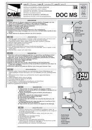
Label Material and PrintingEvery <strong>EntryCom</strong> delivery includes a sheet of transparent foil that can be easilyprinted, with a laser printer. Cut the printed foil into pieces and insert the labels into thename plates. Do not use paper to avoid water logging.Make sure that the text does not cover up the red arrows printed on the nameplate, we recommend you to print the foil using a template (MS Word), available atwww.2n.cz .Single surface buttonName 01Name 0<strong>2N</strong>ame 03Horizontally split buttonName 01Name 04Name 0<strong>2N</strong>ame 05Name 03Name 067. Electrical InstallationCompatibility<strong>EntryCom</strong> is designed for conventional, analogue telephone lines and works regardlessof polarity and line parameters.(Refer to the Technical Parameters) and uses tone(DTMF) or pulse dialling to be programmed. Normally, it is connected to a PBX linehowever It can also be connected to an analogue line or the GSM interface providing awireless installation.Connection to Telephone LineConnect <strong>EntryCom</strong> simply using LINE terminals. The advantage is that the<strong>EntryCom</strong> requires no power supply because all power is fed from the telephone line –except for the button backlight and electric lock, if connected. Nevertheless, <strong>EntryCom</strong>can work without these circuits too and sends an acoustic signal on having beenconnected to a line (or after having been disconnected from the line for a defined periodof time).Printed Circuit Board (PCB) DescriptionExplanatory notes to the figure:1. Terminal board 11. Extension unit connector2. Left button connector 12. Series number3. Display connector 13. Main microprocessor4. Voice memory 14. Configuration jumper block5. One-chip Handsfree telephone 15. Right connector6. Switch 2 connector 16. Jumpers7. Keypad backlight connector 17. <strong>Came</strong>ra connector8. Connector for non-standard functions 18. <strong>Came</strong>ra setting jumpers9. Microphone connector10. Keypad connector19. Loudspeaker connector and panelgrounding21
Description of TerminalsGNDSW1LIGHTLINEVIDEO-+This terminal protects <strong>EntryCom</strong> against static electricity damage.Switch 1 designed primarily for electric doorlock control.These two terminals are connected to the 12V power supply witharbitrary polarity. The power supply can feed the electric lock too.These two terminals are connected to the analogue telephone line withany polarity.Video signal output – used only if a camera unit is included. Thecoaxial cable is connected with an internal conductor to +, withshielding to -.Description of JumpersConnector (8)• Here connect the current call indicator (LED).• Write-protection (if the jumper is mounted).• do not connect• Microphone sensitivity reduction (mount the jumper for noisyenvironments).<strong>Came</strong>ra setting – connector (18): refer to the instructions enclosed to the camera unit.Parallel ConnectionParallel connection of multiple telephone sets was commonly used in the era inwhich telephone lines were rare, It carries unnecessary risks to connect the unit in thisway. It is in no case recommended to connect <strong>EntryCom</strong> in parallel to anothertelephone or another <strong>EntryCom</strong> door communicator. It is neither admissible to useequipment that switches one line between two or more sets (intelligent double branch,etc.).7.1. Common InstalationTypical Electric Lock Connection<strong>EntryCom</strong> contains a solid-state switch equipped with V-MOS transistors, which isable to switch both ac and dc regardless of polarity. Make sure that the current andvoltage values do not exceed limits (refer to the Technical Data) and that the technicalparameters of the lock and power supply are compatible.23
El. lockPowersupplyAC or DC12VTel.lineNever switch 230 or 120 V mains voltage directly!!!If you do not have an electric lock and want to have one, you should select a 12V lock, this being the most common type. Connect the lock according to the figure,which shows the button backlight supply too (see later).Dc-supplied lock: Practically all locks can be dc and ac supplied. The ac supply ismore advantageous because the lock buzzes, which is the clearest signalling methodhowever to use a dc supply lock (from batteries, e.g.), you are recommended to equip<strong>EntryCom</strong> with acoustic signalling (continuous tone during the whole switch activationtime).Caution: If the lock power supply fails and the telephone system carries on working, thekeypad-equipped <strong>EntryCom</strong> system is unaware of the failure the switch will bepassword-activated and the activation is acoustically signalled, but the electric lock willnot work because of the lack of power.Typical Button Backlight Power Supply<strong>EntryCom</strong> features a high-quality white-LED name plate backlight. This backlightshows low power requirements, long life and even illumination of all name plates. If astandard 12 V electric lock (see above) is connected to <strong>EntryCom</strong>, the backlight can bepowered using the lock power supply. Connect the power supply as shown in the figure.Just make sure that the power supply (adapter transformer) is able to supply the24
equired current constantly and that it is cooled properly (do not wrap it in anythermally insulating material, or use ill-ventilating covers, etc.!). The required currentdepends on the count of buttons and other elements in the set and can be determinedfor 12 V according to the following formula:Basic unit without keypad80 mABasic unit with keypad200 mA1 one-side extender unit 80 mA1 two-side extender unit 100 mA<strong>Came</strong>ra130 mAReader150 mADisplay200 mAThe above mentioned currents are maximum values at 12V.Cable Arrangement inside the CoverWe recommend you to use a UTP cable (8-wire, approx. 5.5 mm output diameter) for<strong>EntryCom</strong> connection. Push the cable into the groove on the left side of the cover. Ifyou combine this cable with another one (e.g. the electric lock 2-wire cable), insert the2-wire first and then the UTP cable to prevent the 2-wire cable from falling out. You canalso fit the cables with common clamp tape.WARNING! An improper cable arrangement may cause a malfunction of theproduct. Before closing the cover, check all wires and the cover for perfectclosing.Grounding Terminal Connection - MandatoryAny person that gets in contact with <strong>EntryCom</strong> may carry an electrostatic charge ofseveral thousands of Volts. Drawing one’s finger near to the <strong>EntryCom</strong> metal panelmay result in spark discharge. The purpose of the grounding terminal is to protect the25
product against this discharge. The terminal carries the charge from the panel to theground directly, not through the <strong>EntryCom</strong> circuits.Where no grounding cable is available, it is possible to connect the groundingterminal with any of the telephone line terminals*). In some telephone systems one lineterminal is directly connected with the ground, the others carry current to the groundthrough overvoltage protection.*) Note: This connection eliminates direct connection of the line conductor onto thepanel because there is a protective element between the panel and the groundingterminal.Separate Button Backlight and Electric Lock FeedingSeparate power supplies are necessary where the lock requires voltage higher than 12V. In this case, an additional power supply (12V) must be used to illuminate the buttonbacklight - see the figure below. Other reasons for such connection are the effort tominimise consumption from the back-up supply (which supplies the lock, not thebacklight), or just that two weaker power supplies are availableEl. lockSupplyAC or DCmax.48VSupplyAC or DCmax.12Vtel.lineConnection of Switch 2A new additional switch, Part No. 9135250E, has been designed for <strong>EntryCom</strong>.It can be mounted into any basic unit, as an added option. To connect it, follow theinstructions included in the switch delivery.26
7.2. <strong>Came</strong>ra InstallationThe camera unit, Part No. 9135210E, can be built into any <strong>EntryCom</strong> basic unitduring installation or as an option to be added later. You can also use the camera unit incombination with any Vandal resistant panel. It is a colour CCD camera with highresolution of 420 TV rows, with a monochrome night mode (infrared backlight hiddenunder the nameplates), and has a wide-angle pin-hole lens (90º diagonally) and a tiltinghinge for manual direction adjustment.The camera has a PAL composite output and can be connected to any TVdisplay (e.g. Part No. 9134147E - 7" TFT LCD), or a video server (Part No. 9134145E,MPEG4 LAN video server). A coaxial or twisted cable can be used for connection.A sight glass is included in the delivery, which replaces the non-transparent<strong>EntryCom</strong> basic unit sight glass imitation. To install the camera, follow the instructionsthat come with it.IMPORTANT!To install the camera, use the stabilised 12 V dc power supply. To get a suitable (12V /2A) one, order Part No. 91341481E.7.3. Display InstallationThe display module, Part No. 9135240E, can be built into any <strong>EntryCom</strong> basicunit (excepting units with vandal resistant panel) during installation or as an option to beadded later. It is black & white, graphic LCD with resolution 128 x 64 pixels, whitebacklight and USB interface for configuration.It has memory for up to 1000 characters, and it is controlled by basic modulebuttons and keypad, if present. Each character can be alphanumeric or graphic up towhole display size.A sight glass is included in the delivery, which replaces three button labels on<strong>EntryCom</strong> basic unit. To install the display, follow the instructions that come with it.IMPORTANT!To install the disply, use the stabilised 12 V dc power supply. To get a suitable (12V /2A) one, order Part No. 91341481E.27
7.4. Connection of Extender UnitsThe easy installation of the button extender units is one of the great advantages ofusing the <strong>EntryCom</strong> system. The installation could not be easier - the units areconnected using one cable (included in every extender delivery) in a chain manner(every element in the chain is connected with the preceding one). Every unit has twoconnectors – one input (for connection towards the <strong>EntryCom</strong> basic unit) and oneoutput (for connection of another, remote unit). For proper function and sequence of thebuttons keep the right orientation of the units and do not interchange these connectors!This connector is intended for thenext extension module connection.Maximum Count of Extender UnitsPart No. 9135181E (1x8 buttons) 6 5 4 3 2 1 0Part No. 9135182E (2x8 buttons) 0 0 1 1 2 2 3This table shows that single-button and double-button units can be combined easily.28
Cable Interconnection of Units• Every extender unit delivery contains a connecting cable with identical ends. Theconnection ratio is 1:1. It is impossible to insert the connectors incorrectly becausethey are provided with a key.• The basic unit is always on the left. The extender units are “chained“, each unitbeing connected with its neighbour.• The cable cannot be pulled through the frame-connecting hole until the frames areinterconnected (refer to the Mounting section).This connector is intended for thenext extension module connection.Imortant warning!Extension modules must be interconnected by mounting jumper (tunnel),delivered together with each extension unit. This part is made from conductileplastic. If it is necessary to place extenson unit at some distance, or if you lostthe jumper, you must interconnect metallic covers by another way.29
Button NumberingButton numbering – single-button sets7 15 231 8 16 242 9 17 253 10 18 2611 19 27SameNumbering12 20 28Plan if theunit has akeypad131421222930To be continued to 54Button numbering – double-button sets7 15 23 31 39 471 4 8 16 24 32 40 482 5 9 17 25 33 41 493 6 10 18 26 34 42 5011 19 27 35 43 51Samenumbering12 20 28 36 44 52plan if theunit has akeypad.131421222930373845465354Caution: The Vandal Resistant panels are only available as single-button sets and oneextender unit maximum.Button numbering – infopanel sets:The numbering plan will not change when you install the infopanel name plate,Part No. 9135311E, into an extender unit however 8 numbers will be omitted when youinstall the infopanel, Part No. 9135310E.30
8. ProgrammingAll <strong>EntryCom</strong> parameters, including the keypad ones, are set remotely using anytone-dialling telephone set (or a mobile phone). First call <strong>EntryCom</strong> and enter theprogramming mode. The access to this mode is service password protected.A voice menu is available in the programming mode and so you need not use thismanual to program standard parameters. The menu is stored in the <strong>EntryCom</strong> memoryin the default language. Having entered the full parameter or memory number, you canhear how the parameter has been programmed, thus checking the programmednumbers for correctness.All parameters are stored safely in the non-volatile EEPROM memory. The memorycapacity does not limit the count or length of numbers, passwords, etc. This means thataltogether 324 memories for 16-digit telephone numbers, 54 Arrival/Departure passwordmemories, 20 switch password memories, etc. are available.Tip - Before You Start Programming• Write or print the values to be programmed to minimise the risk of error. Moreover,this gives you an idea of what you have programmed. Make sure that programmingis not barred (JP1 jumper) – refer to the PCB Description subsection.Entering Programming ModeYou can enter the programming mode only during an incoming call (telephone –<strong>EntryCom</strong> call). The programming barring jumper must not be mounted. To get into theprogramming mode, enter the service password in the format password (do notforget to enter the asterisks before and behind the password!). The service password is12345 by default and can be changed ,. If you enter the password correctly, the voicemenu is launched. Now you can start programming.Programming ProcedureYou can set parameters in any order and as many times as you wish. To change aparameter use the following command:Function numberparameterA three-digit function number is assigned to every parameter to be programmedand to every memory (refer to the Programming Chart). This number indicates to<strong>EntryCom</strong> which parameter to change, and is used as "Enter". When it is entered,<strong>EntryCom</strong> repeats the parameter (or memory) number and reads the current contents(excluding passwords). Now you can enter new data – of variable meaning and lengthdepending on the function selected (refer to the Programming Chart). Finally, pressagain for confirmation. <strong>EntryCom</strong> confirms the data saving. Repeat this procedurefor each parameter.Programming Error• Any wrong value can be re-programmed by another command (immediately or anytime later).• If you make a typing error, cancel the entered value with . Then you can re-enterthe whole number.• If you enter an incorrect function number or parameter value, <strong>EntryCom</strong> sends arefusal signal and you have to start with the function number again.• If you do not press any button within a predefined timeout, <strong>EntryCom</strong> sends a hangupsignal and hangs up. The timeout is 5 seconds; every character is followed by30 seconds for you to think over your setting. The 5-second limit starts when31
<strong>EntryCom</strong> has read all that relates to the current user position in the programmingmenu. The timeout can be prolonged – see the chart.Switch Password ProgrammingEach switch can be controlled with up to 10 different passwords that are listed in the<strong>EntryCom</strong> memory. Passwords can be added to the list using functions 811 and 821and deleted with functions 812 and 822 individually. The default status is a singlepassword in the list, namely 00 for switch 1 and 11 for switch 2. These two specialpasswords cannot be entered from the <strong>EntryCom</strong> keypad. To cancel them, you have toremove them from the list:32orFunction 997 deletes the entire password list for both switches including thepasswords 00 and 11. Function 999 deletes the entire password list for both switchestoo but recovers the passwords 00 and 11 and the service password 12345.Password Selection RestrictionsControlling the switches by phone, you can enter the password without any startingand terminating characters and the password length is not limited. <strong>EntryCom</strong> has toverify after every character received whether the password is complete or not.Therefore:make sure that no password is identical with the beginning of another password.• Should you use such confusing passwords for switch control, you have to enter thelonger password (by phone) with asterisks at the beginning and end.• If <strong>EntryCom</strong> refuses to store a password, it means that the switch password list isfull, or the password has already been entered.• The switch password may not be identical with any Arrival/Departure, Day/Night, orservice password.• For password selection tips see the Instructions for Keypad Use.Deleting All Passwords, All Memories, Complete InitialisationThe following three functions facilitate your programming by clearing all previoussettings:997 - deletes the entire password list for both switches including passwords 00 and 11.998 - deletes memories of all buttons (01 - 54) plus Arrival/Departure and Day/Nightpasswords.999 - clears the whole memory and resets the default values (see the chart).Protection against Unintentional DeletionThe above functions need no special parameter but must be protected againstunintentional initiation. Therefore, enter the service password as the function parameter.Warning: Full initialisation takes a few seconds, <strong>EntryCom</strong> sends a continuous tonewhile memory clearing. Functions 997 and 998 take a little less time and are signalledby a continuous tone too.The button memories can be deleted individually too – just enter a “blank” whileprogramming. For example: clears memory 1 of button 01.
9. Full Parameter ChartParameter Parameter Name Range Default NoteUp toAll buttonX X X NUMBER011-54616 blankmemoriesMemory number, 1 - 6digitsButton number, 01 - 54Digits 0-9 can only be entered directly into the memories. Special characters are entered additionally using function XX7:017to547018to548019to549559811821812822813823Enter specialchars, andspaceCount ofautomatic diallingcyclesArrival/DeparturepasswordDay/NightpasswordEnter up to 10switch 1passwordsEnter up to 10switch 2passwordsDelete valid switch1 passwordsDelete valid switch2 passwordsSwitch 1 closingtimeSwitch 2 closingtimeEntering format: X X 7 X X XXButton number, 01 – 541 = 2 = 3 = spaceButton memory number, 1 – 6Character position, 01 - 16Note: The digits behind this position are shifted automatically.X X 8 X0-9 0 = offCount of cycles, 0 - 9Button number, 01 - 54up to 16digitsup to 16digitsup to 16digitsValidpasswordblankblank824 Switch 2 delay 0-25 s 00011X X 9 PASSWORDUp to 16 digitsButton number, 01 - 54The same as for Arrival/Departure, identical for all buttons• Passwords 00 and 11cannot be entered from thekeypad!• Up to 10 switch passwords• Delete passwords usingfunctions 812, 822Deletes individual valid switch1 passwords.Deletes individual valid switch2 passwords.0-9 s 5s 0 = switch disabled0-9 s 5s 0 = switch disabled0 = switch 2 is notsynchronised with switch 1901 Dialling type 0-1 0 = tone 1=pulse 40/60902Dialling timeoutafter pick-up5-99 8 = 0.8s Range of 0.5 - 9.9s903 DTMF level 0-12 6 1 step = 1 dB904Automatic MultipleNumber Diallingtype0-30 = disabledfor allbuttons906 Ticking into call 0-12 0 = off1 = loud with confirmation2 = silent with confirmation3 = SP without confirmation 1 )4 = SP without confirmation 1 )The called party recognisesbetter that the incoming call isfrom <strong>EntryCom</strong>.34
Parameter Parameter Name Range Default Note911Count of ringsbefore incomingcall answering1-99 2Warning!!! No connection isestablished if a higher value isentered than is allowed by thePBX ringing timeout!!!912 Max. call duration 1-99 12=120s Range of 10s-990s913 Log-in timeout 1-99 3 3 = 30 seconds915Hang-up timebetween calls5-99 15 = 1.5s921 Code lock mode 0-1 1 = enabled922Buttons replaced0 = disabled0-1 0 = disabledby keypad1 = enabled923 Telephone mode 0-1 0 = disabled For details on these functions924Tone diallingsee the Keypad Description.0-1 0 = disabledduring call931Microphone0 = Maximum microphone0-3 2power-up levelsensitivity932Automaticresponse speed0-3 2 3 = Maximum response speed933 Reception volume 0-15 7 15 = Maximum reception volume934Transmissionvolume0-15 7 15 = Maximum transmission volume935 Message volume 0-15 7 15 = Maximum message volume936 Beeping volume 0-12 12 12 = Maximum tone volume937DTMF hearing(side tone) volume0-3 3 3 = Maximum DTMF volume938Loudspeakervolume0-15 7 15 = Maximum loudspeaker volume941Minimum continuoustone time<strong>EntryCom</strong> hangs up.If the tone is longer,10 - 99 20 = 2s942Minimum busy toneperiod0-255 8 = 0.08s943Maximum busy toneThese parameters control the0-255 70 = 0.7speriodbusy tone detection. They are944Maximum tonespacedifferenceautomatic dialling.used for call termination and0-255 10 = 0.1s945Minimum count ofbusy tone periods2-9 4951Minimum ringingtone time1 - 200 50 = 0,5 s 2 )The longest ringing period952Minimum longspace must be in the interval5 - 100 10 = 1 sspace timebetween parameters 952 and953Maximum longspace time10 - 100 60 = 6 s953.Count of ringingIf the preset count of periods is1 - 99 10periodsexceeded, the call is terminated.954 If the preset count of periods is exceeded and automatic dialling is enabled, another attemptfollows. In the event of Automatic Dialling without Confirmation, the ringing tone is recognisedand ends before the preset count of periods is exhausted; the call is regarded as successful.Maximum timeout for961pressing the next digit1-9 5 s During password entering, etc.35
Parameter Parameter Name Range Default NotePossibility to hang up0 = no963 by pressing the same1button1 = yes964965971974976977Possibility to dial thenext number bypressing anotherbuttonPossibility to hangup by pressing #(DTMF)Count of messagerepetitionsCommunicatoridentificationnumberlanguage selectionfor a messageabout a callterminationlanguage selectionfor a message ofcalling0 = no1 = yes0 = no1 = yes110 - 9 316digits0 - 8 10 - 8 1-There is a 3-second spacebetween every two messages.The number enablescommunicator identification.0 = 1 = English 3 )2 = Czech 3 ) 3 = Slovak4 = German 5 = Russian6 = Polish 7 = Slovenian8 = Portuguese991 Service password 12345 12345 by default997Deletion ofpasswords of allswitchesServicepasswordDeletes passwords 00 and 11too.998Clearing of allmemoriesClears memories 01 to 55.Full initialisationClears memories 01 to 55999 Warning! Changes the service password too (setting the default value of12345).1 ) Types 3 and 4 of Automatic Dialling without Confirmation differ from each other in how they process veryshort calls (a few seconds). Dialling type 4 regards a call as successful in all cases, type 3 only if the doorwas opened.2 ) New implicit value, a smaller possibility of an unintentional detection3 ) Czech version has language order: 1 = Czech, 2 = EnglishIf You Forget the Service PasswordIf you forget the service password, contact the manufacturer. The manufacturer canchange your service password to 12345 remotely without altering any other parameter.Second Switch Synchronisation -Explanation(The numbers in the figureare parameter numbers.)SWITCH 1SWITCH 2The parameters can be set to overlapactivation of the two switches.SWITCH 1SWITCH 236
Account of parameters 941, 942, 943, 944Busy tonePeriodParameter 942Tone timeSpacetimeParameter 943500 250Example:Tone – space difference is500 – 250 = 250 ms ... Set parameter 944 to 300 ms.Note:Increase parameter 944 also when Hélios is placed in the hall or corridor with a largedecay time.Account of parameters 951, 952, 953Ringing tone (example)Ringing toneLong spaceAt this time <strong>EntryCom</strong> detects,that ringing tone had ended.Param. 952Param. 953 Param. 95337
10. MaintenanceCleaningIf used frequently, <strong>EntryCom</strong>, especially the keypad, gets dirty. To clean it, use a pieceof soft cloth moistened with clean water. We recommend you to obey the followingprinciples while cleaning:• Never use aggressive detergents (such as abrasives or strong disinfectants);• Clean the device in dry weather in order to make waste water evaporate quickly.Label Replacement, Programming Status ChangesFor necessary steps refer to the preceding subsections. Keep the following for later changes:• this manual;• the completed programming form (including a copy);• unused transparent foil strips for button labels.Always use the product for the purpose it was designed and manufactured for, in complianceherewith.The manufacturer reserves the right to modify the product in order to improve its qualities.<strong>2N</strong> <strong>EntryCom</strong> contains no environmentally harmful components. When the product‘sservice life is exhausted and you would like to dispose of it please do so in accordance withapplicable legal regulations.11. Section for Advanced <strong>User</strong>s11.1. Automatic Multiple Number DiallingWhen you press a <strong>EntryCom</strong> button, you may find out that the called line is busyor the called party is absent. <strong>EntryCom</strong> is able to identify these situations and solvethem by Automatic Multiple Number Dialling if one of three automatic dialling modes isenabled. Up to 6 numbers can be stored for each button.The three automatic modes (see below) recognise the continuous, busy andringing tones, In all of these modes, automatic dialling can be disabled or the requiredcount of cycles can be preset (1 to 9; if none of the stored numbers is answered, thewhole cycle is repeated starting with the first number again) for each button separately.You can program Automatic Multiple Number Dialling for selected buttons only,retaining the others in the default mode, the selection of one of three automatic diallingmodes is common.Automatic Multiple Number Dialling without ConfirmationThis mode can be used in common cases to enable the visitor to get througheven if the called line is busy or the called subscriber is absent. Hence, the secondmemory of the button may include the secretary’s number, the third memory the porter‘slodge number, etc.This mode recognises the ringing tone and if the tone ends before the predefinedcount of rings, <strong>EntryCom</strong> regards this as a successful connection, this solution is notfully reliable because detection may be hindered by noise, etc.No message is played back in this mode.38
Evaluation of Situations in Speakerphone Automatic Dialling without ConfirmationSituationBusy toneCall or silence without previousringing toneContinuous tone (at the PBX, e.g.)Ringing tone, which is terminatedbefore 10 rings are made (the countof rings is variable)Ringing tone, 10 rings are made (thecount of rings is variable)to ,<strong>EntryCom</strong> ActionHangs up in approximately 2 seconds and dials thenext number.Waits for the preset timeout (log-in time), then hangsup and dials the next number.Hangs up in approximately 2 seconds and dials thenext number.Regarded as a successful call, continues for themaximum timeout (maximum call duration).For details refer to the text under the table.Hangs up and dials the next number.These digits are interpreted as password beginning.Call extension or password beginning.Hang-up command.If the ringing tone stops before the predefined count of rings is achieved and the call is thus veryshort (e.g. 2 seconds), it is not clear whether the call should be regarded as successful.Therefore, a new type of automatic dialling has been added - type 4. The difference is asfollows:• Type 3 regards such a call as successful only if the door is opened.• Type 4 regards all such calls as successful.Automatic Multiple Number Dialling with ConfirmationThis mode is used where maximum connection reliability is required – foremergency calls. The called line (the supervisory control centre, e.g.) must be operatedby a well-trained person to confirm connection. The DTMF is used as the most reliablecriteria for successful connection. The called line must press on its telephone. If thecalled number is busy or remains unanswered until the preset timeout or in other cases(see the table), <strong>EntryCom</strong> dials the next number in the sequence.Evaluation of Situations in Speakerphone Automatic Dialling with ConfirmationSituation<strong>EntryCom</strong> ActionBusy toneHangs up in approximately 2 seconds and dials thenext number.Call or silenceWaits for the preset timeout (log-in time), thenhangs up and dials the next number.Ringing toneWaits for the preset count of rings, then hangs upand dials the next number.Continuous tone (at the PBX,e.g.)Hangs up in approximately 2 seconds and dials thenext number.DTMF char or Immediately hangs up and dials the next number.DTMF charConfirms reception (2 beeps) and the call continuefor the preset time at most (maximum call duration).These digits are interpreted as control characters -refer to the DTMF Control subsection.39
Note: It is sometimes difficult to recognise the above-described situations reliably due toa poor quality of the PSTN connection. Excessive noise in the surroundings may alsohave a negative impact. However, this may only decelerate automatic dialling (the busytone may not be recognised, e.g.). Even if <strong>EntryCom</strong> cannot identify the DTMF, theconnection is established (yet for a shorter time).Silent Automatic Multiple Number DiallingThis mode fully conceals the fact that a telephone call is made. When a button ispressed, the loudspeaker is off and no PBX or dialling tone can be heard. Theloudspeaker is switched on when the called subscriber confirms connection (bypressing on its telephone). Thus, a potential thief cannot establish whether the calledperson is in the building or not.Otherwise, the function is the same as with Automatic Multiple Number Diallingwith Confirmation.MessagesThere are situations in which the calling person does not want to or cannot speakfor security reasons in the automatic dialling mode. In these cases, <strong>EntryCom</strong> can playback a message stored in its memory. The test series includes the “Wait please,connection is being established" message. Later, more messages will be available tothe user.DTMF ControlIf Automatic Multiple Number Dialling with Confirmation or Silent AutomaticMultiple Number Dialling is enabled, <strong>EntryCom</strong> can be controlled as shown in the tablebelow. For convenience, commands 1 to 5 are arranged as they are usually used.DTMFCHARACTERororto ,FUNCTIONConfirmation indicating to <strong>EntryCom</strong> that a call was successful.<strong>EntryCom</strong> sends its confirmation signal, the call goes on until theend of timeout and any of the following commands can be used.Message muting (during playback).WARNING! You may not speak while <strong>EntryCom</strong> is playing backthe message!!!Message re-plays (once).Call extension: a call is extended by 30 seconds by thiscommand. Can be used repeatedly.Call termination.These digits are interpreted as a password beginning - for switchcontrol.Notes:• These commands do not work in the Automatic Multiple Number Dialling modewithout Confirmation!• The above-mentioned commands may not be accepted due to poor connection ifsent during a message. To avoid this, press the button during the time of silence(between messages).40
11.2. Arrival/Departure, Day/Night Modes<strong>EntryCom</strong> can identify easily where to “route” (switch) a call after a button is pressed.All you have to do is call <strong>EntryCom</strong> and enter the following:I‘m leaving:I‘m back:passwordpasswordAll buttons can be switched all at once by a common Day/Night password orindividually by separate Departure/Arrival passwords.How does switching work?• Every button has memories for 6 numbers (intended primarily for Automatic MultipleNumber Dialling).• If the Automatic Multiple Number Dialling mode is OFF, memory 1 is used for the Daymode and memory 3 for the Night mode. This is a simple two-number switching.• If the Automatic Multiple Number Dialling mode is ON, memories 1, 2, 3, 4, 5, 6 areused for the Day mode and memories 3, 4, 5, 6 are used for the Night mode in theabove-mentioned order. This accelerates the process; numbers that would not beanswered are skipped over.• If the Night mode is on and memories 3 to 6 are empty, memories 1 and 2 are used.• If the Night mode is on, memories 1 and 2 are omitted for all buttons and thiscannot be disabled individually using the Arrival function.• In the Day mode, the buttons assigned to persons who used the Departure function(are on a leave) shall remain in the Night mode until the same persons use theArrival function (after the leave, e.g.).Example 1 – administration building, automatic dialling is off:Button 01: labelled Mr. Smith, memory 1 = Mr. Smith‘s line, memory 3 – secretary‘sline, password for button 01 is 777.1. Mr. Smith is leaving for holiday. He calls <strong>EntryCom</strong> and enters: 777 1 .2. A visitor comes, presses Mr. Smith‘s button – <strong>EntryCom</strong> calls the secretary.3. Mr. Smith comes back. He calls <strong>EntryCom</strong> and enters: 777 0.Example 2 – family house, Silent Automatic Multiple Number Dialling:Button 01: labelled The Johnsons, memory 1 = living room, 2 = workshop, 3 = Mr.Johnson’s mobile telephone, 4 = Mrs. Johnson‘s mobile telephone.Arrival/Departure password for button 01 is 333.1. The family is leaving for holiday. They call <strong>EntryCom</strong> and enter: 333 1 .2. A visitor presses the Johnson’s’ button – <strong>EntryCom</strong> calls Mr. Johnson‘s mobilephone and, if unsuccessful, Mrs. Johnson‘s mobile phone.3. Etc.41
12. Technical Parameters12.1. Telephone ParametersParameter Value ConditionsMinimum required off-hook line current 15 mA Off-hookMinimum required on-hook line voltage 20 V Hang-upDC voltage drop (off-hook)< 8 V< 16 VI = 25 mAI = 50 mALead current while hang-up < 25 μA U = 60 VOff-hook AC impedance220 Ω + 820 Ω115 nF parallel20 to 60 mAReturn loss > 10 dB 20 to 60 mABandwidth 300 to 3500 Hz 20 to 60 mARinging impedance> 2 kΩC = 1 μF25 to 50 HzRinging detector sensitivity 10 to 20 V 25 to 50 HzTime of response to ringingVariablePulse dialling 40 / 60 ms 20 to 60 mADTMF level-6 and -8 dB 20 to 60 mA± 2 dBDTMF detector sensitivity Min. -40 dB 20 to 60 mADial tone detector sensitivity Min. -40 dB 350 - 500 HzBusy tone detection speed Variable 350 - 500 HzContinuous tone detection speed Variable 350 - 500 HzRinging tone detection speed Variable 350 - 500 HzOvervoltage protection – common mode 1000 V 8 / 20 μsOvervoltage protection – between A, Bconductors1000 V 8 / 20 μs12.2. Other ParametersSwitch – max. voltageSwitch – min., voltageSwitch – max. currentBacklight – rated voltageBacklight – max. voltageBacklight – currentconsumptionOperational temperaturerange48 V AC, DC9 V AC, DC2 A AC, DC12 V24 Vup to 1 A-20 to + 60 ºCCoverage IP 53Dimensions (1 module) 210x100x29 mm (h x w x d)Weightup to 500 g42
<strong>2N</strong> TELEKOMUNIKACE a.s.PRAGUE: Modřanská 621, 143 01 Praha 4,tel.: +420 261 301 333,fax: +420 261 301 999,e-mail: sales@2n.cz,www.2n.cz© 2007, <strong>2N</strong> TELEKOMUNIKACE a.s.. - Prague DR 1322v2.0