Navigator (.pdf) (240360480,4802,8802,S) - Sabine, Inc.
Navigator (.pdf) (240360480,4802,8802,S) - Sabine, Inc.
Navigator (.pdf) (240360480,4802,8802,S) - Sabine, Inc.
- No tags were found...

Create successful ePaper yourself
Turn your PDF publications into a flip-book with our unique Google optimized e-Paper software.
SABINEthe sound of innovation13301 US Highway 441 Alachua, FL 32615 Phone (386) 418-2000 Fax (386) 418-2001 www.<strong>Sabine</strong>.com
Su m m a r y o f Fe at u r e sEC - De c l a r at i o n o f Co n f o r m i t ySeSe c tt i i o n NiNi n e: e: ApAp pp ee n d i i c ee ssDe c l a r at i o n o f Co n f o r m i t yEC - DECLARATION OF CONFORMITYCE Ma r k i n gSABINE, INC.13301 NW US HIGHWAY 441ALACHUA, FLORIDA USAdeclare that the productEQUALIZERSABINE MODEL NAVIGATORIs in conformity withCouncil Directive: 73/23/EEC and 89/336/EEC (EMC Directives)Standards to which conformity is declared:EN 60065: 1993EN 60742: 1995EN 55103-1: 1997EN 55022: 08:94 + a1:05:05EN 55103-2: 1997Manufacturer’s Signature:Date: SEPTEMBER 30, 2005 Name: Doran Oster, <strong>Sabine</strong> President
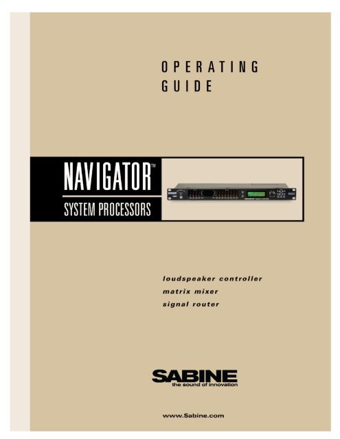
Su m m a r y o f Fe at u r e sNAVIGATOR SERIES:• Front Panel Controlable• Line Inputs• Remote Control Wall Panel Ready• Ethernet Control ReadyNAV240-U (2 x 4 System Processor)NAV360-U (3 x 6 System Processor)NAV<strong>4802</strong>-U (4 x 8 System Processor)NAV<strong>8802</strong>-U (8 x 8 System Processor)NAVIGATOR S SERIES:• No Front Panel Control (for security)• Mic / Line inputs• Remote Control Wall Panel• Ethernet Control ReadyNAV240-S (Blank Front 2 x 4 System Processor)NAV360-S (Blank Front 3 x 6 System Processor)NAV<strong>4802</strong>-S (Blank Front 4 x 8 System Processor)NAV<strong>8802</strong>-S (Blank Front 8 x 8 System Processor)NAVRC-100 (Wall-mounted remote control panel [requires -R Option])• 24-bit A/D and D/A conversion, 40-bit extended processing• 20 to 20 KHz Frequency Response• +18 dBu Maximum Signal Input & Output• Floating Point SHARC Processor• 115 dB dynamic rangeEach Input/Output channel provides• Precise control of Level and Polarity• Parametric Filters: up to 8 filters, numeric or graphic control• Crossover: Bessel, Butterworth, and Linkwitz Riley filters; slopes to 48 dB/octave• High Shelf Filter (3KHz to 20KHz) and Low Shelf Filter (20 Hz to 1KHz)• FBX Feedback Exterminator: 8 Filters, with Setup Mode• Compressor/Limiter, with controls for ratio, threshold, attack, release, and gain• Digital Delay, up to 650 (80 on 240 & 360) msec delay, adjustable in 21 microsecond increments• Bypass: dedicated switches for all functions• Channel Select buttons that toggle between Mute and Edit, with easy linking• LED Indicators: Edit, Mute, Level• LCD Display: All parameters and status displays• Store up to 30 programs• Multiple levels of password security• Front panel RS232 and USB connections for computer control<strong>Navigator</strong>2 Remote for Windows TM Software included with every unit; runs up to 16 <strong>Navigator</strong>s:All front panel controls, plus more, including:• Graphic filter adjustments• Password protection• View & edit frequency response curves• Store and recall files, setups, programs• Control and link up to 16 <strong>Navigator</strong>s (<strong>4802</strong> and <strong>8802</strong> units only)• Future-proof FREE Flash RAM upgrade capability: upgrade your firmware and software using <strong>Sabine</strong>’s<strong>Navigator</strong> Upgrade WizardOperating Guide Version 2.0 for 2010 <strong>Sabine</strong> <strong>Navigator</strong>s with:<strong>Navigator</strong> Firmware Version 6.19 and up • <strong>Navigator</strong> Remote Software Version 6.9 and up<strong>Navigator</strong>2_OperatingGuide110928.indd5
Ta b l e o f Co n t e n t sTable of ContentsNotesSummary of Features...........................................................................................................................................................5Section One: Introduction...................................................................................................................................................7Section Two: Front & Back Panel Views.............................................................................................................................8Section Three: <strong>Navigator</strong> Applications..............................................................................................................................93.1 Installed Audio........................................................................................................................................................................ 93.2 PRODUCTION Audio................................................................................................................................................................. 10Section Four: Using <strong>Navigator</strong> Front Panel Controls......................................................................................................114.1 Quick Start Guide to the <strong>Navigator</strong> Front Panel.................................................................................................... 12Section Five: Operating the <strong>Navigator</strong>.............................................................................................................................135.1 Input menus....................................................................................................................................................................... 14-165.2 Output Menus................................................................................................................................................................... 16-185.3 GLOBAL PARAMETERS Menus.......................................................................................................................................... 18-225.4 INPUT/OUTPUT REFERENCE GUIDE....................................................................................................................................... 235.5 FEEDBACK CONTROL and PARAMETRIC EQUALIZATION.................................................................................................... 245.6 FBX OPERATING INSTRUCTIONS....................................................................................................................................... 25-26Section Six: Using <strong>Navigator</strong> Remote Software .............................................................................................................276.1 SYSTEM REQUIREMENTS AND RECOMMENDATIONS.......................................................................................................... 276.2 CONNECTIONS.......................................................................................................................................................................... 276.3 INSTALLING and using THE SOFTWARE.............................................................................................................................. 286.4 Upgrading <strong>Navigator</strong> Firmware and Software........................................................................................................ 286.5 <strong>Navigator</strong> remote CONTROL screenS...................................................................................................................... 29-316.6 Saving your work: <strong>Navigator</strong> Files and Programs ............................................................................................... 326.7 CREATING A NAVIGATOR NETWORK (NAV<strong>4802</strong> and NAV<strong>8802</strong> Only)................................................................................. 33Section Seven: Using Optional <strong>Navigator</strong> Hardware and Software Features...............................................................357.1 COntrolling options on blank front panel units................................................................................................. 367.2 wall mounted remote control panel (R Option)............................................................................................... 37-407.3 Mic preamp (M option)......................................................................................................................................................... 41Section Eight: <strong>Navigator</strong> Engineering Specifications....................................................................................................43Section Nine: Cautions & Warranty..............................................................................................................................44-456
Se c t i o n On e: In t r o d u c t i o nSection One: IntroductionCongratulations on your purchase of the <strong>Sabine</strong> <strong>Navigator</strong>. These products are our latest versionsof the popular <strong>Navigator</strong> System Processors.The new <strong>Navigator</strong>s come in four basic input/output configurations. The NAV240 is a 2 by 4 , theNAV360 is a 3 by 6, the NAV<strong>4802</strong> is 4 by 8, and the NAV<strong>8802</strong> is an 8 by 8. These System Processorsare equally at home in both touring and installation applications, where they provide loudspeakermanagement, matrix mixing, and signal routing. State-of-the-art hardware and firmware guaranteesuperior sound quality and reliability.All firmware and software can be upgraded using <strong>Sabine</strong>’s Upgrade Wizard software, included onyour <strong>Navigator</strong> CD.Aside from the powerful array of features packed into a single unit (multiple crossovers, completesignal routing and mixing, FBX filters, parametric filters, high and low shelf filters, delay, compression,and limiting), the <strong>Navigator</strong> also offers a choice of user interfaces.Computer control: When you install the included <strong>Navigator</strong> Remote Control Software you will seea very powerful yet simple user interface. All parameters and system status monitors are availablewithout burying you in cryptic menus. From here you control all audio, security, linking, and file savingfunctions, and you can manage your entire network of <strong>Navigator</strong>s.Front Panel Control: The <strong>Navigator</strong> combines the best of both worlds. The front panel provides accessto every audio and system function for each device. Gain control for each input and output is onetouch away. LED signal meters for each input and output provide a clear picture of signal status, andediting is fast with the datawheel and cursor keys. Quickly control multiple channels simultaneouslyby pressing several channel buttons at the same time, which is very handy for those global changes.Also available in Blank Front Panel.NAVRC-100 Wall-Mount Remote Panel: The attractive NAVRC-100 wall-mounted remote controlpanel allows for control of presets, gain, muting, and other basic functions. One NAVRC-100 cancontrol up to 2 <strong>Navigator</strong>s, and one <strong>Navigator</strong> can be controlled by up to 32 NAVRC-100 panels.Serial Remote Control Devices: <strong>Navigator</strong>s are compatible with all the major serial controllers,including Crestron, AMX, and Cue.How to Use this Operating GuideDetailed instructions are provided for all front panel controls, but you will probably be able to get goingafter taking a look at the Quick Start page. The instructions apply to all <strong>Navigator</strong>s except wherenoted.Later in this guide is an overview of installing and using the <strong>Navigator</strong> Remote Control Software. Formore detailed information please see the Help section of the software.If you have any questions you may call <strong>Sabine</strong>’s Customer Service Department at 386-418-2000from 9:30 am to 6:00 pm EST.<strong>Navigator</strong>2_OperatingGuide110928.indd7
Se c t i o n Tw o : Fr o n t & Ba c k Pa n e l Vi e wsSection Two: Front & Back Panel ViewsNAV240 Front PanelTypical - all front panel control units follow this schemeUSB ConnectorConnect your computer forsoftware controlInput & Outputsignal indicatorsEDIT ButtonEngages Channel Edit modeLCD DisplayMenu keysScroll throughavailable menusData wheelEdits parametervaluesCursor keysMoves cursor throughavailable parametersRS232 Serial ConnectorConnect your computer forsoftware controlChannel Select ButtonsSelects each input oroutput channel for eitherMuting or EditingNAV<strong>4802</strong>-S Blank Front PanelTypical - all blank front panel units follow this schemeMUTE ButtonEngages Channel MutemodeENTER ButtonConfirms actions when inGlobal ScreensGLOBAL ButtonGo to Global ParametersScreensHOME ButtonBack to HomeScreenNAV<strong>4802</strong>USB ConnectorConnect your computer forsoftware controlPower LightGlows red whenunit is turned onNAV<strong>4802</strong> Back Panel (<strong>8802</strong> has euro connectors only)Typical - all front panel control units follow this scheme - options varyEternet Connector**Wall Panel Remote Connector + **OutputsInputsOutputsInputsNAV<strong>4802</strong>-S Back PanelTypical - all blank panel units follow this scheme - options varyWall Panel Remote Connector + **Eternet Connector**RS232 Serial ConnectorMic Preamp**OutputsInputsOutputsInputs+NAVRC-100 required **Available options8
Se c t i o n Th r e e: Nav i g at o r Ap p l i c at i o nsSection Three: <strong>Navigator</strong> Applications3.1 Installed AudioHouse of WorshipNAV<strong>4802</strong>Laptop ControlConference Room - Distributed AudioNAV<strong>8802</strong><strong>Navigator</strong>2_OperatingGuide110928.indd9
Se c t i o n Th r e e: Nav i g at o r Ap p l i c at i o ns3.2 PRODUCTION AudioStereo 3-way, with SubsNAV<strong>4802</strong>Left, Center, RightLaptop ControlNAV36010
Se c t i o n Fo u r: Us i n g Nav i g at o r Co n t r o l sSection Four: Using <strong>Navigator</strong> Front Panel Controls4. 2.5.7.8.NAV<strong>4802</strong>3.1.6.9. 10. 11.BLUE Edit LEDfor each channelRED Mute LEDfor each channel1. MUTE Button: Select this to turn the Channel Select Buttons into MUTE buttons. Each press ofa Channel Select button toggles that channel’s Mute Status, and the RED Mute LED will light indicatingthe channel is muted.2. EDIT Button: Select this to turn the Channel Select Buttons into EDIT buttons. Each press ofa Channel Select toggles that channel’s Edit Status, and the BLUE Edit LED will light indicating thechannel is in Edit Mode.3. Channel Select Buttons: Selects the corresponding channel for either Editing or Muting asdescribed above. Press again to toggle off either Edit or Mute modes. When in Edit mode the LCDmenu display pertains to the channel(s) that are selected. The last modified menu will be displayedon the LCD.CHANNEL LINKING: Linking multiple channels is accomplished by pressing multiple input or outputchannel select buttons at the same time. In this way you apply your edits to multiple channelssimultaneously. Linking is very powerful - it simplifies programming for common parameter valuesacross multiple channels. Multiple inputs can be linked together and multiple outputs can be linkedtogether. You cannot link inputs to outputs.4. Peak Level LEDs: Indicates the current peak level of the Input of Output Signal. Ranges areSignal (anything below -12 dB), -12dB, -6dB, -3dB, Clip/Limit. The Input Clip LED references to thedevice’s maximum headroom. The Output Limit LED references to the threshold of the limiter.TECH TIPFor fast scrollingof frequency ordelay values,hold the Enter Keywhile turning thedatawheel5. LCD: Shows all the necessary information for editing all parameters.6. Rotary Data Wheel: Changes parameter data values. The wheel has travel velocity sensingwhich allow for large or small incremental data changes. For extra coarse modification of delay andfrequency (1 Hz resolution) values, pressing the Enter key simultaneously will increment/decrementthe data value by 100 X.7. MENU Buttons: The two Menu buttons move through the menus in a linear format.>: Next menu screen8. CURSOR Buttons: After choosing a menu to work with, use these keys to move through eachof the editable parameters within the Menu in a linear format. These also move the cursor in certainscreens.: Next parameter or cursorposition9. ENTER Button: Press this key to execute changes in the Global Parameters Screens and in theFBX Setup Screen to initiate Setup Mode. Fast scrolling with the Enter key: Press this key whileturning the data wheel to modify delay and frequency (1 Hz resolution mode) data values by 100X.10. GLOBAL Button: Choose this button to enter the special Global Parameters menu.11. HOME Button: Choose this button to return to the <strong>Navigator</strong>’s Home screen, which displays themodel number and the last loaded preset. This also exits both Edit and Mute modes.11<strong>Navigator</strong>2_OperatingGuide110928.indd
Se c t i o n Fo u r: Us i n g Nav i g at o r Co n t r o l s4.1. Getting Started with the <strong>Navigator</strong> Front Panel· After powering up the unit, the following initialization screen is displayed on the LCD:NAV<strong>4802</strong>*· The initialization process takes about 8 seconds and during that period the unit boots and displaysthe <strong>Navigator</strong> firmware version.· After the initialization process is finished the <strong>Navigator</strong> displays its main creen:NAV<strong>4802</strong>*· The screen shows the current program number and program name assigned to the unit. The programassigned is always the last program the user recalled or stored before powering down the unit.The <strong>Navigator</strong> is now ready to go.4.1.1 Configuring The <strong>Navigator</strong>Working with your <strong>Navigator</strong> is easy. Follow these basic steps as a guide to setting up the your system.For details on working within each menu, please read Section Five on operating the <strong>Navigator</strong>.1. Signal Routing: You first need to get your inputs routed to the appropriate outputs. You can dothis in two ways.A. Press Enter to enter the Global Parameters Menu, press the >>Menu key until you get tothe Configuration Menu, and choose one of the preset configurations. This is the fast wayto get all your routing done.B. Or you can press the Select key on one of the outputs, press the >>Menu until you get to theSource Menu, and choose which of the inputs you want to patch to this particular output.2. Set Input/Output Gain: The first menu you see when pressing the Select key on each input oroutput is the Signal Menu. The cursor is already in the Level field, and you can immediately turn thedatawheel to adjust the input and output gain of each channel. This fast access to gain is very handyfor quick adjustments during your program.3. Mixing: Mixing for each output is done in the Source Menu of each output (see 1.B. above). Inthis menu each input has a gain control so you can set the levels to create just the right mix in thisparticular output.4. Crossover Filters: At this point you may want to set the crossover filters for each of the outputs.You are essentially controlling which band of frequencies you will send to each of your speakers orspeaker systems. Press the Select key for the output you want to set, and press the Menu key untilyou get to the XOVER Menu. You will set filters for the lower and upper rolloff points, the slopes ofthe filters, and type of each filter.5. Equalization: You may want to adjust the frequency response of your system. The <strong>Navigator</strong>gives you a powerful set of EQ tools. For each input and output you can use up to eight filters, andthese can be either Parametric, High Shelving, or Low Shelving filters. Press the Select button onany input or output channel to access the EQ Menu.6. FBX Feedback Exterminator: Each input channel includes 8 patented FBX feedback control filters.Use the FBX Mode menu to begin Setup Mode for maximum gain before feedback. See the resultsof the process in the FBX Menu, and change the default FBX parameters on the FBX Global Menu.7. Save your work: You know how important this one is. If you are editing in the input/output menus,press Home to get to the Main Menu. Then press Global to get to the Global Parameters Menus, andscroll to the Store Menu. Save and name your program here. Do it early and often!12
Se c t i o n Fi v e: Op e r at i n g t h e Nav i g at o rSection Five: Operating the <strong>Navigator</strong>5.1 Input menusEach of the <strong>Navigator</strong> input channels has a separate Menu key. There are 7 function menus for eachinput channel, and you cycle through these by pressing the Menu keys. The first line in the LCD indicateswhich input channel you are editing, and shows the name of that channel if you have addedone (for example, IN_1: ____), The menus are arranged in a linear fashion. Scroll to the right toreach the end, then scroll back to the left until you reach the beginning. Use the Cursor keys to selecta parameter to edit, and use the Data Wheel to make your edit.SignalNAV<strong>4802</strong> & NAV<strong>8802</strong> NAV240, 360NAV240, 360, 480LCD Display hasonly 2 lines. UseCursor key toaccess all parametersin eachwindow· LEVEL: Gain, -40.00 dB to +15.00 dB in 0.25 dB steps.· POL: Polarity, can be normal (+) or inverted (-).· DELAY: Delay in 21 microsecond steps. Can be displayed inms, ft or m. The time unit of the delay can be changed in theGlobal Parameters menu. The maximum delay is 80 ms inthe NAV240 and 360. And, maximum delay is 650 ms in theNAV<strong>4802</strong> and<strong>8802</strong>.EQNAV<strong>4802</strong> & NAV<strong>8802</strong> NAV240, 360· EQ#: Selects one of the 8 available equalizer filters.· LEVEL: Adjusts EQ level. Ranges from -30.00dB to +15.00dBin 0.25dB steps.· FREQ: EQ center frequency. Ranges from 20 to 20,000 Hzin either 1 Hz steps or 1/36 octave steps. The frequency stepscan be selected in the Global Parameters Menu.· BW: EQ Bandwidth. Ranges from 0.02 to 2.50 octaves insteps of 0.01 octave steps for PEQ. The Q value is automaticallyshown beneath the octave value. For Lo-Shf or Hi-Shf, itis either 6 or 12dB/Oct.· Type: Type of EQ. The types can be PEQ (parametric), Lo-Shf (Low shelving), and Hi-Shf (High shelving).<strong>Navigator</strong>2_OperatingGuide110928.indd13
Se c t i o n Fi v e: Op e r at i n g t h e Nav i g at o rFBXFBX Feedback ExterminatorNAV<strong>4802</strong> & NAV<strong>8802</strong> NAV240, 360See Section 5.6for a complete descriptionof howto operate theFBX FeedbackExterminator· EQ#: Selects one of the 8 available FBX filters.· TYPE: Choose Fixed for more gain before feedback, Dynamicfor control of new feedback during the show. See section 5.5for a complete guide to using the FBX function.· LVL: Shows level in dB of the FBX filter (not editable).· FREQ: Shows center frequency of the FBX filter (not editable).· BW: Shows the width of the FBX filter (not editable).FBX-Global ParametersNAV<strong>4802</strong> & NAV<strong>8802</strong> NAV240, 360· LOCK: This refers to Fixed filters only, which by definitionalready are fixed in their centerpoint position. Locking preventsthe filter from getting deeper. Locked is the recommendedsetting. Ready Mode automatically locks fixed filters.· BYPASS: Bypasses all FBX filters on this Input channel. Onindicates bypass; Off indicates FBX is active.· RSTDYN: Reset Dynamic FBX filters. Turning to on togglesthe reset function.· DEPTH: Sets maximum depth of all FBX filters on this inputchannel. Range is 0 to -84dB.· WIDTH: Sets default width of all FBX filters on this inputchannel. Range is 0.01 to 1.00 octave.· SENS: Sets the Sensitivity of the FBX algorithm to the differencebetween music and feedback. Range is 1-5.· PERS: Sets persistence - how long feedback can persistbefore a filter is set. Range is 1-5.· Factory Defaults are recommended for Sensitivity, and Persistencesetting.14
Se c t i o n Fi v e: Op e r at i n g t h e Nav i g at o rFBX-ModeNAV<strong>4802</strong> & NAV<strong>8802</strong> NAV240, 360· SETUP MODE: This screen is used to engage FBX Setupmode. Use this for setup only - not for use during the show.This step provides maximum gain before feedback. Followon-screen instructions and raise gain slowly. For a step-bystepguide to using the FBX see section 5.6.DuckerNAV<strong>4802</strong> & NAV<strong>8802</strong> NAV240, 360Not availableNAV240, 360, 480LCD Display hasonly 2 lines. UseCursor key toaccess all parametersin eachwindowSet the priority of each input on the <strong>Navigator</strong> as it relates to the Ducker function. Lower priorityinputs will be attentuated as higher priority signals are present. Priorities range from 1 (highest) to9 (lowest).CompressorNAV<strong>4802</strong> & NAV<strong>8802</strong> NAV240, 360· THRESH: Compressor Threshold. Ranges from -20 to+20dBu in 0.5dB steps.· ATTACK: Attack time. Ranges from 0.3 to 1ms in 0.1mssteps; from 1 to 100ms in 1ms steps.· RELEASE: Release time. Can be set at 2X, 4X, 8X, 16X or32X the attack time.· RATIO: Set compression ratio, 1:1 to 40:1 (Limit.BypassNAV<strong>4802</strong> & NAV<strong>8802</strong> NAV240, 360· DELAY: Select X using the datawheel to bypass the delay· EQ: Select X to bypass one of 8 EQ filters on this input<strong>Navigator</strong>2_OperatingGuide110928.indd15
Se c t i o n Fi v e: Op e r at i n g t h e Nav i g at o rChannel NameNAV<strong>4802</strong> & NAV<strong>8802</strong> NAV240, 360· Name: Channel name. The maximum length is 6 characters. Use the datawheel to scroll throughall the possible characters, and use the cursor keys to move to the next space. Once the name iscreated it will appear in the upper field of this window.5.2 Output MenusEach output channel of the <strong>Navigator</strong> has a separate menu key. There are 6 menus for each outputchannel. The menus cycle in a linear fashion, just like the input menus. Use the Cursor keys to selecta parameter to edit, and use the Data Wheel to make your edis.SignalNAV<strong>4802</strong> & NAV<strong>8802</strong> NAV240, 360· LEVEL: Gain, -40.00dB to +15.00dB in 0.25dB steps.· POL: Polarity, can be normal (+) or inverted (-).· DELAY: Delay is adjustable in 21 microsecond steps anddisplayed in ms, ft or m. The time unit of the delay can bechanged in the Global Parameters menu. The maximumavailable delay is 650ms (80 for the NAV240, 260).EQNAV<strong>4802</strong> & NAV<strong>8802</strong> NAV240, 360· EQ#: Selects one of the 8 available Equalizer filters.· LEVEL: EQ level. Ranges from -30.00dB to +15.00dB in0.25dB steps.· FREQ: EQ center frequency. Ranges from 20 to 20,000 Hzin either 1Hz steps or 1/36 octave steps. The frequency stepscan be selected in the Global Parameters menu.· BW: EQ Bandwidth. Ranges from 0.02 to 2.50 octaves insteps of 0.01 octave steps for PEQ. The Q value is automaticallyshown beneath the octave value. For Lo-Slf or Hi-Shf, itis either 6 or 12dB/Oct.· Type: Type of EQ. The types can be parametric (PEQ), Lo-Shf(Low shelving), and Hi-Shf (High shelvin).16
Se c t i o n Fi v e: Op e r at i n g t h e Nav i g at o rCrossoverNAV<strong>4802</strong> & NAV<strong>8802</strong> NAV240, 360NAV240, 360, 480LCD Display hasonly 2 lines. UseCursor key toaccess all parametersin eachwindow· FTRL: Choose the type of low frequency filter (high pass).Types can be Buttwrth (Butterworth), Link-Ri (Linkwitz-Riley)or Bessel.· FRQL: Filter cut-off frequency of low frequency crossoverpoint (high pass). Ranges from 20 to 20,000Hz in either 1Hzsteps or 1/36 octave steps. Select frequency resolution in theGlobal Parameters menu.· SLPL: Filter Slope of low frequency crossover point (highpass). Ranges from 6 to 48dB/octave in 6dB/octave steps. Ifthe selected Filter Type is Linkwitz Riley, the available slopesare 12 / 24 / 36 / 48 dB/octave.· FTRH: Choose the type of high frequency filter (low pass).Types can be Buttwrth (Butterworth), Link-Ri (Linkwitz-Riley)or Bessel..· FRQH: Filter cut-off frequency of high frequency crossoverpoint (low pass). Ranges from 20 to 20,000Hz in either 1Hzsteps or 1/36 octave steps. Select frequency resolution in theGlobal Parameters menu.· SLPH: Filter Slope of high frequency crossover point (lowpass). Ranges from 6 to 48dB/octave in 6dB/octave steps. Ifthe selected Filter Type is Linkwitz Riley, the available slopesare 12 / 24 / 36 / 48 dB/octav.CompressorNAV<strong>4802</strong> & NAV<strong>8802</strong> NAV240, 360· THRESH: Compressor Threshold. Ranges from -20 to+20dBu in 0.5dB steps.· ATTACK: Attack time. Ranges from 0.3 to 1ms in 0.1ms steps;from 1 to 100ms in 1ms steps.· RELEASE: Release time. Can be set at 2X, 4X, 8X, 16X or32X the attack time.· RATIO: Set compression ratio, 1:1 to 40:1 (Limit).<strong>Navigator</strong>2_OperatingGuide110928.indd17
Se c t i o n Fi v e: Op e r at i n g t h e Nav i g at o rInput SourceNAV<strong>4802</strong> & NAV<strong>8802</strong> NAV240, 360· 1, 2, 3, 4 – Input channel source for the current output channel. This is your sub-mixer for eachoutput of the <strong>Navigator</strong>. Values range from 0.00 (Maximum level) to -40, then OFF, which mutes thatinput for the output you are editing.Channel NameNAV<strong>4802</strong> & NAV<strong>8802</strong> NAV240, 360· Refer to the Input Menus for details on naming your output chanels.BypassNAV<strong>4802</strong> & NAV<strong>8802</strong> NAV240, 360· DELAY: Select X using the datawheel to bypass the delay· EQ: Select X to bypass one of 8 EQ filters on this output5.3 GLOBAL PARAMETERS MenusThe Global Parameters Menus allow you to control and change global parameters that are relatedto the general operation of the <strong>Navigator</strong>. Press HOME to access the Main Menu, then GLOBALto enter the Global Parameters Menus. All Global Menus require you to press the ENTER key toconfirm the selected edit.Program RecallNAV<strong>4802</strong> & NAV<strong>8802</strong> NAV240, 360The <strong>Navigator</strong> has a built in non-volatile memory that can store up to 30 different program setups. Aprogram can be recalled sing this menu.· PROG: Program Number to be recalled..· NAME: Program Name of the program. This is read only; names can be changed in the Storemenu.18
Se c t i o n Fi v e: Op e r at i n g t h e Nav i g at o rProgram StoreThe <strong>Navigator</strong> has a built in non-volatile memory that can store up to 30 different program setups.A program can be stored using this menu. The old program with the same program number will bereplaced. Once the program is stored in the flash memory, it can be recalled at a later time, even aterpower down.NAV<strong>4802</strong> & NAV<strong>8802</strong> NAV240, 360· PROG: Program Number for the current data to be stored.· NAME: Program Name, allows a maximum length of 12 charactersConfigurationNAV<strong>4802</strong> & NAV<strong>8802</strong> NAV240, 360· MODE - configures the mode of operation.Mode: Out 1 Out 2 Out 3 Out 4 Out 5 Out 6 Out 7 Out 8None Any Any Any Any Any Any Any AnyStereo 2-Way In1 In1 In2 In2 Any Any Any AnyStereo 3-Way In1 In1 In1 In2 In2 In2 Any AnyStereo 4-Way In1 In1 In1 In1 In2 In2 In2 In2The unit assigns the Input source for the corresponding outputs when the Mode of Configuration isselected. The crossover point parameters like the filter type, cut-off frequency and slope have to beconfigured manually in the Xover Menu in each Output menu.*Note: The configuration mode configures the input sources when selected. The user can change thesource afterwards if desired. It does not keep the configuration in memory.Copy ParametersNAV<strong>4802</strong> & NAV<strong>8802</strong> NAV240, 360Copy channel parameters from the source to the target. Whenthe Source and Targets are both Inputs or Outputs, all audioparameters will be copied. When one of the Source or the Target is an input while the other is anoutput, only the Level, Polarity, Delay and EQ are copied.· SOURCE: Channel to be copied from.· TARGET: Channel to be copied to.<strong>Navigator</strong>2_OperatingGuide110928.indd19
Se c t i o n Fi v e: Op e r at i n g t h e Nav i g at o rGeneral System ParametersNAV<strong>4802</strong> & NAV<strong>8802</strong> NAV240, 360· FREQ MODE: Selects the frequency control mode for EQand crossover filters. The coarse adjustment is 36 steps/octave;choose All Frequencies (1 Hz resolution) for fine adjustments.· DELAY UNIT: ms (milliseconds), ft (feet), or m (meters).CommunicationsNAV<strong>4802</strong> & NAV<strong>8802</strong> NAV240, 360· PORT: Choose control port. RS232/USB for direct connectionto a computer, or CAT-5 for Ethernet.· BAUD: Choose the baud rate to match your serial port when connecting via RS232 or USB. Thevalues are 1200, 2400, 4800, 9600, 19200, 38400, 57600, or 115200.· DEVICE#: Assigns the device ID from 1 to 16. Assigning ID numbers is required when you arecreating a network of more than one <strong>Navigator</strong>.PanelNAV<strong>4802</strong> & NAV<strong>8802</strong> NAV240, 360Choose how your <strong>Navigator</strong> wil interact with the NACRC-100Wall Panel Remote. For a complete look at using this withyour <strong>Navigator</strong> please see section XXX on pageXX· PANEL MODE: Master or Slave. The first <strong>Navigator</strong> to be controlled with multiple wall pales shouldbe set to Master. The next one is set to Slave. You can control a maximum of 2 <strong>Navigator</strong>s with onewall pane.· # OF PANELS: 1 to 32. Choose the number of wall panels that control this <strong>Navigator</strong>. The maximumis 32.20
Se c t i o n Fi v e: Op e r at i n g t h e Nav i g at o rEthernetNAV<strong>4802</strong> & NAV<strong>8802</strong> NAV240, 360You can set the parameters for Ethernet connections in this window. Each <strong>Navigator</strong> in a networkmust have a unique IP address. This adjustment is also available in the <strong>Navigator</strong> Software. SeeSection 6.7 of this guide for a complete explanation of creating a <strong>Navigator</strong> Network using standardEthernet connections.• IP ADDRESS: Unique network address of the <strong>Navigator</strong>. Number above is a good place to start.• GATEWAY ADR: Default address of a network. Set as shown above unless your network administratorrecommends another setting.• SUBNET MASK: Limits what the <strong>Navigator</strong> can see on the network. Set as shown above.• Cycle Power When Finished.I/O ModeNAV<strong>4802</strong> & NAV<strong>8802</strong> NAV240, 360Not availableFor units with the “D” option for Digital I/O, only available on NAV <strong>4802</strong> or <strong>8802</strong> units. Choose theInput/Ouput type for each pair of inputs or outputs. A = Analog, and D = Digital.• I12: A = Input pair 1 and 2, set to Analog, etc.• O34: A = Output pair 3 and 4, set to Analog., etc.Mic PreampNAV<strong>4802</strong> & NAV<strong>8802</strong> NAV240, 360Not available - controlled withback panel switchesFor units with the “M” option for Mic Preamp. Choose either Mic level or Line level for each input.This front-panel switching is only available on NAV<strong>4802</strong> or <strong>8802</strong>. NAV240 and 360 have back panelswitches for this function.• 1: Mic = Input 1 set to Mic Level• 2: Line = Input 2 set to Line Level, etc.• P: On = Phantom Power turned on for all inputs<strong>Navigator</strong>2_OperatingGuide110928.indd21
Se c t i o n Fi v e: Op e r at i n g t h e Nav i g at o rPriority InputsNAV<strong>4802</strong> & NAV<strong>8802</strong> NAV240, 360Not availableHere you set the global parameters for the Ducker function of the <strong>Navigator</strong>. Each input can have itsown priority setting (see Input Menus). The settings here effect all ducking functions for each channel.· RELEASE: Release time of gain reduction. Ranges from 0 to 504 ms· ATTACK: Attack time of gain reduction. Ranges from 0 to 504 ms· THRESH: Threshold at which gain reduction begins. Ranges from 0 to 90 dB· ATTENUATE: Attenuation of the mic when gain is reduced. Ranges from 0 to 90 dB· DWELL ATK: Time high-priority signal is above threshold before gain reduction begins on low prioritymics. Ranges from 0 to 1054 ms· DWELL RLS: Time high-priority signal is below threshold before gain reduction releases. Rangesfrom 0 to 1054 msSecurityNAV<strong>4802</strong> & NAV<strong>8802</strong> NAV240, 360The <strong>Navigator</strong> enables the user to secure the unit and prevent undesired changes in the setup. Inorder to make changes to the security levels the user must enter the crrect password.· MENU - Selects the menu to be locked/unlocked. The options are:• In-Signal: Input Signal Menu (Level, Polarity, Delay).• In-EQ: Input EQ Menu.• In-Name: Input Channel Name Menu• Out-Signal: Output Signal Menu (Level, Polarity, Delay).• Out-EQ: Output EQ Menu.• Out-Xover: Output Crossover Menu.• Out-Limit: Output Limit Menu.• Out-Source: Output Source Menu.• Out-Name: Output Channel Name Menu.• Global Parameters: Global Parameters Menu· LOCK: Engages lock (Yes) or unlock (No) for the corresponding menu.· PASSWORD: Enter your 4-character password here. Initial password creation must be done within<strong>Navigator</strong> Remote Software. Entering the same password here initiates the lockout function. PressEnter and your <strong>Navigator</strong> front panel controls will be locked according to the menu selections youmade. You can alter those selections via the front panel or through the software. NAV240 and 360models do not allow for selective menu locking. With these all front panel functions are either lockedor unlocked.22
Se c t i o n Fi v e: Op e r at i n g t h e Nav i g at o r5.4 INPUT/OUTPUT REFERENCE GUIDEThis chart shows all the parameters and edit values for each control on each menu. Use this as yourreference for ranges of all parameters in each menu.Parameters Min Max StepsUnitsLevel Signal LEVEL -40 15 0.25 dBPolarity Signal POL+ / -Delay Signal DELAY 0 21,600 1 21us stepsEQ Number EQ EQ# 1 6 1EQ Level EQ LEVEL -30 15 0.25 dBEQ Frequency EQ FREQ 20 20,000 1 HzEQ Bandwidth EQ BW 0.02 2.5 0.01 OctaveCrossover Low XOver FTRLOff / Butterworth / Linkwitz-Riley / BesselCrossover Low XOver FRQL 20 20,000 1 HzCrossover Low XOver SLPL 6 48 6 dB/octaveCrossover High XOver FTRHOff / Butterworth / Linkwitz-Riley / BesselCrossover High XOver FRQH 20 20,000 1 HzCrossover High XOver SLPH 6 48 6 dB/octaveLimiter Threshold Limit THRESH -20 20 0.5 dBuLimiter Attack Limit ATTACK 0.3 100 0.1/1 msLimiter Release Limit RELEASESource Select Source 1, 2, 3, 4Channel Name Ch-Name NAME2 / 4 / 8 / 16 / 32X Attack timeOff / On6 characters<strong>Navigator</strong>2_OperatingGuide110928.indd23
Se c t i o n Fi v e: Op e r at i n g t h e Nav i g at o r5.5. FEEDBACK CONTROL and PARAMETRIC EQUALIZATIONOperation of the FBX Feedback Exterminator section of the front panel of your <strong>Navigator</strong> is simple,but may require a brief explanation for those of you unfamiliar with <strong>Sabine</strong> FBX products and/or terminology.Let’s begin by defining a few key terms.5.5.1. Glossary of Terms• FEEDBACK describes what happens when a loudspeaker disperses sound back into an amplified microphone,at a level sufficient to allow one or more frequencies to ring out of control. Feedback can occur atany frequency, but is especially painful at mid to high frequencies. The specific frequencies that feedback ina particular situation depend on the acoustics of the environment, the placement of the microphone(s) andspeaker(s), the response characteristics of the sound system components, and the volume of amplification.Anyone who has operated a sound system or attended a conference or a concert is familiar with feedbackand its unpleasant consequences!• A PARAMETRIC EQUALIZER allows the user to precisely specify three critical values that determine anequalizer’s characteristics: the center frequency of the EQ band that is boosted or cut (measured in Hertz),the amount of boost or cut imposed at the center point (measured in dB), and the width of the bell-curveshaped frequency band that is affected (typically measured in octaves).• An FBX FILTER is essentially an automatically placed, narrowly attenuated parametric filter, with the centerpoint of its narrow cut tuned to a precise frequency that feeds back when a sound system amplifies one ormore microphones to a sufficient volume. The <strong>Navigator</strong> will automatically place up to 8 FBX filters in thesignal path, corresponding to 8 distinct frequencies of feedback.• A FIXED FBX FILTER will not move from the original set frequency of the filter. Once it sets itself, it remainsat the same frequency. The system’s gain before feedback is limited primarily by the number of fixed filters;i.e., increasing the number of fixed filters increases the system’s gain before feedback. However, unlessit is LOCKED, a FIXED FILTER may move its notch deeper without changing frequency. Fixed filters aretypically set by turning up system gain to the point of feedback prior to sound check or performance, andthey represent the “first layer” of feedback protection.• A DYNAMIC FBX FILTER acts like a Fixed filter, until all available FBX filters (Fixed or Dynamic) are in useand a new frequency begins to feedback. When this happens, whichever Dynamic filter was set earliest inthe performance will drop its original frequency and move to the new one. Dynamic filters are especiallyuseful with mobile or wireless microphones (where feedback frequencies may change due to microphonerepositioning) and represent the “second layer” of feedback protection. Note that both Fixed and Dynamicfilters can be set while music is playing (except when in Setup Mode). One of the distinguishing propertiesof the <strong>Sabine</strong> FBX algorithm is its ability to distinguish music (or speech, or other sounds) from feedback.• A LOCKED FBX FILTER is a Fixed filter locked in place; i.e., it cannot get any deeper or change its frequency.Locked fixed filters are no longer adaptive. Locking Fixed filters ensures your first layer of feedbackprotection is always in place -- highly recommended.• FILTER WIDTH generally refers to the width (measured in octaves, or fractions thereof)of a filter, including graphic EQ filters, parametric filters, and FBX filters. More specifically, width is definedby determining the outer frequencies (surrounding the filter center point) that are altered ± 3 dB when thefilter is imposed.• CONSTANT Q filters are filters whose widths remain constant regardless of the amount of boost or attenuationimposed by the filters. Constant Q feedback control filters are defined several different ways in ourindustry. Some companies claim their filters are Constant Q because they do not widen when measured atthe deepest part of the filter. Under this meaningless definition, every feedback filter ever made is ConstantQ. However, the top end of these filters get wider and wider as the filter gets deeper. In other words, theytake out more of the program as the filter gets deeper. <strong>Sabine</strong> Constant Q filters uses the most stringentand meaningful definition. Our filters never get wider than the specified width when measured at the top ofthe filter (-3 dB point). Our filters never remove more of the program as the filter gets deeper.• FBX Setup Mode refers to <strong>Sabine</strong>’s exceptionally fast method of placing FBX filters during sound systemsetup. Think of Setup mode as your key to achieving one of the main benefits of the FBX: getting more gainbefore feedback. In Setup the FBX is very sensitive so do not talk into the mics during setup, and tryto keep room noise to a minimum. Setup is designed to allow feedback to occur at lower input levels, and itimposes a strong limiter on the feedback output as it occurs. The net result is that you are able to ring outfeedback more quickly, and at a much quieter level!NOTE: MAKE SURE Setup Mode IS OFF and Ready Mode IS ENGAGED WHEN YOU USE THENAVIGATOR OR YOUR AUDIO SIGNAL QUALITY MAY SUFFER!5.6. FBX OPERATING INSTRUCTIONSFollow these steps to obtain the maximum gain before feedback, with minimal or no loss in the tonal24
Se c t i o n Fi v e: Op e r at i n g t h e Nav i g at o rquality of your program. You should always setup one channel at a time by turning down the otherchannels of the mixer or power amplifiers.STEP ONE: EQUIPMENT SETUPSet up your sound system and position all the speakers and microphones you anticipate using. Whenpossible, avoid placing microphones directly in front of speakers. Patch the <strong>Navigator</strong> into the system(refer to section Three for installation configurations). Set your levels for nominal performance butavoid raising the gain enough to induce feedback. If you are using a graphic EQ, adjust only for thedesired tonal qualities, but DO NOT NOTCH FOR FEEDBACK. If there is any equipment in the signalpath that incorporates a noise gate function, you MUST DISENGAGE these noise gates prior to thesetup procedure. You may reengage them upon setup conclusion. For best results setup your FBXon one input channel at a time. You can mute the audio in the other input channels.FBX BypassBe sure and takethe FBX sectionout of Bypassbefore setup! Dothis in the FBXGlobal Menu.STEP TWO: CHOOSE YOUR FILTER TYPES and REMOVE BYPASSThe default filter setting for your <strong>Navigator</strong> are 6 FBX Fixed Filters and 2 FBX Dynamic Filters perinput channel. You may change that mix of filters, and this should be done before you enter SetupMode. You can always alter the mix of FBX filters and repeat the Setup procedure. To change filtertypes, choose the FBX Menu in the Input Channel you are working on.The factory default for the FBX is BYPASS: On, which means the FBX section is Bypassed. Beforeyou start FBX Setup, select the input channel you are working on, then go to the FBX Global Menu.Set the BYPASS to Off, meaning the FBX section is now active.STEP THREE: ENGAGE SETUP MODE - RESET FILTERSChoose an input channel and select the FBX-Mode Menu. Using the datawheel select “Setup” in theSETUP MODE field, then press ENTER. Press ENTER again to confirm Setup Mode. Setup modeclears all Fixed & Dynamic filters. Do not use Setu mode dring your performance.Press enter to begin Setup -NAV<strong>4802</strong>, <strong>8802</strong> (above), NAV240,360 (below)Raise gain slowly; Setup automatically ends orgot to Ready mode any time by pressing Exit -NAV<strong>4802</strong>, <strong>8802</strong> (above), NAV240,360 (below)STEP FOUR: RAISE MASTER GAINMake sure your power amplifier is turned up and your microphones are turned on. Slowly raise themaster gain of your mixer (or the submix for this input channel of the <strong>Navigator</strong>) until the first feedbackbegins. The FBX will quickly remove the feedback by setting the first filter. Continue to raise the gainslowly. Try to avoid making two or more frequencies feed back at the same time, which sometimeshappens if the gain is raised too quickly. As new frequencies feed back, new filters will be placed.(Note: sometimes the same frequency will feed back a second time, and an earlier filter will notchmore deeply.)Continue raising the gain. Setup mode will end and Ready mode will be engaged in one of twoways:1. All of the Fixed filters and at least the first Dynamic filter are set. This will automatically turnSetup Mode off and the FBX Menu window will be displayed. At this point STOP RAISING THEGAIN!2. You’ve set as many filters as you need or want, even though you haven’t used them all. PressEXIT to prevent any more Fixed filters from setting, or any of the set Fixed filters from notchingmore deeply. Pressing EXIT exits Setup Mode and the FBX Menu window will be displayed.You are now ready to begin your program!<strong>Navigator</strong>2_OperatingGuide110928.indd25
Se c t i o n Fi v e: Op e r at i n g t h e Nav i g at o rNAV<strong>4802</strong> & NAV<strong>8802</strong> NAV240, 360See the results: In the FBX Menu you can view the parameters of all your FBX Filters. Scroll throughall the filters in the FBX# field. You may edit the type of filter, but not the level (LVL), width (BW), orfrequency (FREQ). You may want to create parametric filters based on the results of your FBX Setup,then repeat the Setup procedure to maximize system gain.5.6.1. FBX Setup Mode Cautions & Alternate Setup ProcedureSetup Mode is designed to allow fast and quiet feedback elimination during setup. Setup Mode shouldONLY be used for pre-performance setup. DO NOT USE Setup Mode DURING A PERFORMANCE!This will produce distorted audio and set filters on music or audio program. Setup Mode also may notwork well during setup in a very noisy environment. To speed up feedback elimination, Setup relaxesthe FBX criteria for distinguishing “good” audio from feedback and places filters more readily. If theenvironment is noisy, there is a greater likelihood of placing a filter on audio that is not feedback.If you are working in a noisy environment you can still get the benefit of the Setup procedure, whichis more gain before feedback. Instead of starting in the FBX Mode Menu, begin in the FBX GlobalMenu. This procedure will still eliminate feedback very quickly, though not as quickly as Setup Mode,and without reducing the volume of the feedback before it is filtered out.1. Change the LOCK setting to Off. Now the Fixed filters are available to react to feedback.2. Follow Step Four of the Setup procedure outlined above -- raise the gain for this input channel.3. Continue raising the gain until you achieve the gain before feedback you require, or you set all thefixed filters. You can see the results of this procedure in the FBX Menu (shown above).4. VERY IMPORTANT: Go back to the FBX Global Menu and set LOCK to On. This will lock thefixed filters and prevent them from going any deeper. If you use the factory default settings you willstill have two dynamic filters available for automatic feedback control during the program.Whether or not Setup Mode is used, the end result of setting up FBX filters should be identical. Yoursound system will have clearer, louder, feedback-free sound.5.6.2. FBX Feedback Exterminator - Global ParametersA unique feature of the FBX Feedback Exterminator is the ability to adjust the way the algorithm reactsto feedback. Unlike other feedback controllers, you can create and save your own customizedversions of the FBX.See section 5.1 Input Menus for instructions on using the Global parameters of the FBX.Sensitivity and Persistence are controls that allow the speed and analysis of the FBX algorithm tomatch the type of audio program. Some audio programs, notably certain types of classical music,produce occasional waveforms that are difficult to distinguish from acoustic feedback. The factorydefault Sensitivity and Persistence values should work in almost all conditions; however, you maychange them if necessary to prevent the possibility of triggering a false filter, or to more quickly setthe FBX filters. There is a trade-off between speed of filter placement and how carefully the filter isplaced. More demanding audio sources (that is, program material with musical content that is similarto feedback, like flutes and organs) may require higher Sensitivity & Persistence settings, which willslightly slow down the speed of filter placement, but decrease any possibility of mistaking programaudio for feedback. Lower settings are recommended when you need faster reaction during speechonlyprograms.26
Se c t i o n Six: Us i n g Nav i g at o r Re m o t e Co n t r o l So f t wa r eSection Six: Using <strong>Navigator</strong> Remote SoftwareThe <strong>Navigator</strong>s are designed with easy-to-use front panel controls. You can experience the full capabilityof the <strong>Navigator</strong> by using the <strong>Navigator</strong> Remote Software, which opens up a whole new level ofprogrammability. With the software you get increased storage capacity -- save an unlimited numberof programs as files, transfer files from one unit to another, and download and upload an entire set ofprograms to your <strong>Navigator</strong>. You can also view and edit every function very quickly and arrange variousfunctions on screen to suit your needs. These setups or screensets can be saved and recalled.All <strong>Navigator</strong> models come equipped with the hardware and software necessary to run the units viaremote control from a Windows-equipped computer. Your unit should include one CD ROM that includesthe <strong>Navigator</strong> Software and the <strong>Navigator</strong> Upgrade Wizard for future upgrades of your firmware.6.1. SYSTEM REQUIREMENTS AND RECOMMENDATIONS1. PC computer equipped with Pentium processor 400 MHz or faster and hard disc with at least 20MB of available space for program files.2. Windows 2000 or higher and SVGA or greater resolution graphic card and monitor.3. One COM port for RS232 or USB serial connection, with a 16550 or faster UART chip.6.2. CONNECTIONSConnection via RS232 serial port if your computer has a 9-pin COM port. Use a standard 9-pinmale to standard 9-pin female RS-232 connector, available from most computer stores. For connectingmultiple <strong>Navigator</strong>s you will need to have the NAV<strong>4802</strong> or <strong>8802</strong> versions which include the built-inEthernet interface for use with a network switch/hub, or use a separate COM port for each <strong>Navigator</strong>.Connect the computer’s COM port to the front panel <strong>Navigator</strong> RS-232 jack. Do not use any connectorsthat are wired for a null modem.Connection via USB port is easy. Using a standard USB cable (Type A to Type B connector as shownbelow) connect the <strong>Navigator</strong>’s front panel USB port to your computer’s USB port. USB drivers areautomatically installed when you install the <strong>Navigator</strong> software.Your computer (Type A) <strong>Navigator</strong> front panel (Type B)TECH TIPSTry these tips if you arehaving difficulty connectingyour <strong>Navigator</strong> unit(s)to a Windows PC.1. Software Version. Make sure the software version installed in your computer is compatible withthe firmware version of your <strong>Navigator</strong>. Read the release notes at www.<strong>Sabine</strong>.com.2. Check cable. For RS232 you need a serial 9-pin, not a null modem.3. COM Port. Make sure the COM Port selected is correct. If not you may get an “Invalid Port” messagewhen running the software. Click OK and then correct the port setting. You may have to restart thesoftware. Also make sure no other serial devices are using that COM port.4. Find the COM when using USB. The driver for the <strong>Navigator</strong>’s USB port is installed when youinstall the <strong>Navigator</strong> software. USB COM ports are assigned dynamically by your computer, so youwill need to find out which COM port is being used by your USB-connected <strong>Navigator</strong>.a. With the power on connect the <strong>Navigator</strong> to your compuiter using a USB cable. You will see amessage in your System Tray indicating the new USB device has been found.b. In Windows, click Start and select Settings, Control Panel, then double click System.c. Click on Hardware, Device Manager and open up Ports (COM & LPT).d. You will see the USB driver assigned to one of the COM ports. Use this COM port number whensetting up the connection in the <strong>Navigator</strong> software (Step 4 on the next page).5. Refresh your COM Ports. This is a good choice if you are having trouble connecting.In Windows, click Start and select Settings, Control Panel, then double click System.Click on Hardware, Device Manager and open up Ports (COM & LPT).Right click the COM Port for your <strong>Navigator</strong> and select Remove (or Uninstall).Your computer will verify your intent and then reboot. As it reboots, it will rebuild your COM Port file.This will clean out previous settings for devices no longer attached to your computer and may allowthe <strong>Navigator</strong> software to locate your unit(s).NOTE: COM Port Properties & Settings (Bits per second, Data bits, Parity, Stop bits & Flow control) are controlled by the <strong>Navigator</strong> Software and need not be adjusted.<strong>Navigator</strong>2_OperatingGuide110928.indd27
Se c t i o n Six: Us i n g Nav i g at o r Re m o t e Co n t r o l So f t wa r e6.3. INSTALLING and using THE SOFTWAREFollow the on screen instructions for installing the <strong>Sabine</strong> Remote Control Software for the <strong>Navigator</strong>.If you are using the <strong>Navigator</strong> in a network see Section 6.7 for details.After the installation you should have a <strong>Navigator</strong> software icon on your desktop. We also suggest youinstall the <strong>Navigator</strong> Upgrade Wizard software. This will come in handy when you want to upgradethe firmware in your <strong>Navigator</strong>.Connecting to your <strong>Navigator</strong>:1. First you need to setup the <strong>Navigator</strong>’s front panel settings.For connecting via RS232 or USB: Press the Global button and then the >Menu keyto get to the Comm Menu. The port should be RS232/USB; the baud rate should be115200; the device number should be #1.For connecting via Ethernet: Press the Global button and then the >Menu key to getto the Comm Menu. The port should be CAT-5; the baud rate should be 115200; thedevice number should be unique in each <strong>Navigator</strong> within your <strong>Navigator</strong> network. Startwith #1 and number them sequentially.2. Patch the serial connection to your computer using a standard 9-pin RS232 serial cable or USBcable and run the <strong>Navigator</strong> Software. If you are using an Ethernet connection patch your Ethernetcable from your network switch to the connector on the back of the <strong>Navigator</strong>. For moreinformation on Ehternet connections, see section 6.7.3. The opening screen allows you to choose the Live Mode for connecting to the <strong>Navigator</strong> or DesignMode for offline editing while not connected to a <strong>Navigator</strong>. Choose Live Mode to connect.4. In the Connection Setup screen choose your comm port (RS232/USB) or IP numbers (network)for the device number you are using (device numbers can be changed in the <strong>Navigator</strong> unit in theGlobal Parameters: General menu on the front panel). For connecting to one <strong>Navigator</strong> selectDevice 1, and select RS232/USB. For more about connecting to a <strong>Navigator</strong> Network, see section6.7.NOTE: If you are using USB as your connection please read the Tech Tip on the preceding pagefor important information on finding the correct COM port for your USB connection.5. With the proper COM port (or IP numbers) selected to which you patched your <strong>Navigator</strong> (usuallycom 1 or 2) click the “Connect!” button. Your unit is connected when the System Statusdisplay on the upper left of the main screen shows “Up Sync OK” or “Link OK.” Refer tothe illustrations on the following page for a look at the connection status screens.6. If you have any trouble connecting, see the Tech Tip on this and the previous page.Once you are connected you can proceed to use all the powerful features of the <strong>Navigator</strong>. For abasic explanation of all controls on the main screen, please see the following page.6.4 Upgrading <strong>Navigator</strong> Firmware and SoftwareThe firmware is the internal operating system of your <strong>Navigator</strong> unit. Software is the program youinstall on your computer to control the <strong>Navigator</strong>. Your <strong>Navigator</strong> CD includes the <strong>Navigator</strong> UpgradeWizard program. You will use this program to upgrade the firmware in your unit. You can do this anytime in order to get any recent improvements or added features.Here is the procedure for upgrading your firmware.1. Use your browser and visit www.<strong>Sabine</strong>.com amd choose Professional Audio Products. Click tothe <strong>Navigator</strong> page, choose Firmware Upgrades, and download the latest firmware. You can savethe file anywhere on your computer, but make a note of it!2. Run the <strong>Navigator</strong> Upgrade Wizard and follow the on-screen instructions. You will be asked tochoose the firmware file, and here you will point to the file you downloaded from <strong>Sabine</strong>.com.3. Continue with the on-screen instructions and you will complete the firmware upgrade.28
Se c t i o n Six: Us i n g Nav i g at o r Re m o t e Co n t r o l So f t wa r e6.5. <strong>Navigator</strong> remote CONTROL screenSConnection ScreensThese screens are used for making the software connection to your <strong>Navigator</strong> in LiveMode. See section 6.3 for more information on connecting your <strong>Navigator</strong>.Connection Setup ScreenConnection Status Displays1. The green area on this screen says “Connecting,” whichindicates your computer and the <strong>Navigator</strong> establishing thecontrol connection.2. When the connection is successful you will see the message“Up Sync OK” (shown below) and then “Link OK.”Main ScreensThere are two ways to view the main screen: Mixer or Matrix, as shown on the following page.Guide to Main Screen Menus:• File (Open, Save, Open Setup, Save Setup, New Setup, Exit): Open and Save refer to the.NDAT files which are used to store and recall parameters of the <strong>Navigator</strong> on your computer.These are equivalent to Programs, which are stored in the <strong>Navigator</strong>. Setup files are used tosave other parameters. Think of Setups as your screen sets and network settings. Customdesktop arrangements can be saved and recalled. Links between units are also saved inSetups (.XST files). See section 6.6 Saving Your Work for a complete explanation.• View: Displays the values for every parameter in the <strong>Navigator</strong>. You can print these from here,too.• Device: Choose which <strong>Navigator</strong> to control when connected to a <strong>Navigator</strong> Network.• Function: (Link, Copy, Reset All, Security, Device Name, Preferences) Link opens the screenwhere you can establish multiple link groups and link any parameter across any number of<strong>Navigator</strong>s. Copy opens a screen that allows for flexible copying of any parameter to any<strong>Navigator</strong>. The Security screen provides for password creation and selection of which frontpanelmenus will be locked when using a password. Device Name is just that, and Preferencesallows for default units for delay, EQ bandwidth, and temperature.• Program: From here you can recall or save a Program into the memory of the <strong>Navigator</strong> (ratherthan as a file on your computer). All programs stored within your <strong>Navigator</strong> can be transferredto your PC using Upload All to PC. You can also transfer the files stored on your computer tothe <strong>Navigator</strong> as programs using Download All to Device. See section 6.6 Saving Your Workfor a complete explanation.• Connection: Setup allows you to choose how to connect to one or multiple <strong>Navigator</strong>s. Thiswindow is also displayed when you choose Live Mode from the welcome screen. Connect tothe <strong>Navigator</strong> via RS232or USB as well as Ethernet (NAV<strong>4802</strong> or <strong>8802</strong> only).<strong>Navigator</strong>2_OperatingGuide110928.indd29
Se c t i o n Six: Us i n g Nav i g at o r Re m o t e Co n t r o l So f t wa r eMain Screen - Mixer ViewThis view allows you to work with the <strong>Navigator</strong> processing in a traditional mixer view. Eachinput and output has its own set of processing. Your inputs and outputs also have select buttonsfor routing - just like a mixer. Set up your groups using the buttons at upper right - each groupcan be named and can have its own set of linked functions.Main Screen - Matrix ViewThis view gives you a “processor block” format for working with your <strong>Navigator</strong>. The features arethe same as in Mixer View. With this screen you can get a sense of the routing and signal flow ofyour <strong>Navigator</strong>s.30
Se c t i o n Six: Us i n g Nav i g at o r Re m o t e Co n t r o l So f t wa r eThis is one of the most commonly used screens. Controls for all other screens work in a similar way.Guide to Crossover Screen Controls:• View: Use these buttons to choose which Output graph you will view. You can view multipleoutput response curves. In this example Outputs 1, 2, and 3 are shown.• Control: Use these buttons to choose which Output you will edit using the controls below thegraph area. You can only control one output at a time. In this example we are controillingOutput 2.• EQ Type: Choose between Parametric, Low Shelf, and High Shelf using the pull-down menu.You must choose a filter type before any editing.• EQ Freq.: Set the frequency of the filter center points by typing in a number or using the Slidertool. Note that the scale for ther Slider tool is dynamic - when you choose Frequency thescale displays Hz.• EQ Width: Set the bandwidth of each filter by typing a number into the field or using the Slidertool. Remember to select the field before using the Slider, which shows fractions of an octavein the scale.• EQ Depth: Set the EQ filter depth (or level) by typing a number into the field or using the Slidertool, which shows level setting in dB.• Crossover Type: Sets the type of filter you will use for each of the crossover filters (low or high)in the selected output. Use the pull-down menu to choose the type -- your first step beforeany other editing of the crossover.• Crossover Freq.: Set the frequency at which the filter roll-off begins typing in a value or usingthe Slider tool. Choose the Freq field first and you will see the Slider’s scale display the rangeof vaules at either end of the Slider. You can also edit the filter frequency by grabbing theFilter Handle with your mouse and dragging it along the bottom of the graph display.• Crossover Slope: Set the slope of the filter by typing in a number or using the Slider tool. Youcan also edit the slope dragging the circles that flank the Filter Handle. You will see the slopechange as you adjust these handles.<strong>Navigator</strong>2_OperatingGuide110928.indd31
Se c t i o n Six: Us i n g Nav i g at o r Re m o t e Co n t r o l So f t wa r e326.6. Saving your work: <strong>Navigator</strong> Files and ProgramsYour <strong>Navigator</strong> provides several ways of saving and recalling parameters, and these are useful forpreserving your work. We use the terms Program and File to distinguish where the information isstored. Using the <strong>Navigator</strong> Software gives you access to both the Programs and the Files. If you areoperating the <strong>Navigator</strong> from the front panel you only have access to the programs.1. Programs: These are saved and recalled from the front-panel of the <strong>Navigator</strong>. These are storedin the <strong>Navigator</strong>’s internal memory, and there are 30 possible programs, or presets. Please seesection 5.3 for the instructions on how to Save, Name, and Recall these internal programs fromthe front panel of the <strong>Navigator</strong>. You may also recall and save these <strong>Navigator</strong>-based programsfrom within the <strong>Navigator</strong> software by choosing the Program menu. Remember, these programsare stored in the <strong>Navigator</strong>. It is possible to transfer these programs as a group from the <strong>Navigator</strong>to your computer, or from the computer to the <strong>Navigator</strong>. See the NLT Files section below.2. Files: These saved and recalled on your computer, just like any other file stored on your harddrive. Using your computer as a platform gives you unlimited memory storage of <strong>Navigator</strong> files.There are three types of files associated with the <strong>Navigator</strong>:NDAT files: These files are the equivalent of one of the 30 programs that can be stored withinthe <strong>Navigator</strong>, except in this case they are stored on your computer. All parameters for one<strong>Navigator</strong> are stored in an .NDAT file. You can store as many of these as you need on yourPC. These are accessed using Open File or Save File from the File menu in the <strong>Navigator</strong>software. If you are working in the <strong>Navigator</strong> software and you would like to save your workdirectly into the <strong>Navigator</strong> as a program (you must be connected in Live Mode to do this)choose Recall or Save from the Program menu in the software.NLT files: These files store a listing of 30 <strong>Navigator</strong> programs. Store and recall these usingthe Download and Upload functions in Program menu of the <strong>Navigator</strong> software. Think ofthese files as a way to store all 30 programs of a <strong>Navigator</strong> in one place. This can be handyif you need to make a backup of everything stored within the <strong>Navigator</strong>. Or you may want tocategorize your programs according to applications. These can be downloaded to the <strong>Navigator</strong>all at once using NLT files. Use the upload function to transfer the 30 programs fromthe <strong>Navigator</strong> to your PC. Think of it this way: uploading copies Programs and saves them asFiles on your computer. The default location for these files is the C:\Program Files\<strong>Sabine</strong>\<strong>Sabine</strong> <strong>Navigator</strong> directory on your PC. Here are the step by step procedures for uploadingand downloading.Upload All To PC: Choose this from the Program Menu. This action overwritesprevious uploads - you will get a warning asking you to confirm. If you want keeppreviously uploaded programs you should rename the files in the <strong>Sabine</strong> <strong>Navigator</strong>directory. The upload process creates 30 files, with default names Program 1.ndat,Program 2.ndat, etc.Download All to Device: Choose this from the Program menu. You will see a screenthat lists all the programs, from 1 to 30. Next to each Program is a button that allowsyou to load a <strong>Navigator</strong> file (NDAT) into that program number. Go ahead and loadup to 30 files. This is a good way to get your programs in the order you need themin the <strong>Navigator</strong>. Once you have loaded these files into as many programs as youneed, its time to save this list as an NLT file. Choose Save List. When you want torecall an NLT file you already made, choose Load List. If you want to start a freshlist, choose Clear List.If you like the current list of files and you want to transfer them to the <strong>Navigator</strong>,choose To Device. This will take up to 30 minutes, and it will load these NDAT filesas programs into the <strong>Navigator</strong>. This overwrites the <strong>Navigator</strong>’s programs, so be sureDownload All to Device Screen you are ready to do this.XST files: These Connection Setup files are for storing and recalling computer connectioninformation. This file stores all your IP addresses and comm port selections. You can createand save these files with various connection schemes, for connecting to a single <strong>Navigator</strong>or a group of networked <strong>Navigator</strong>s. Access these by choosing Setup from the Connectionmenu.
Se c t i o n Six: Us i n g Nav i g at o r Re m o t e Co n t r o l So f t wa r e6.7. CREATING A NAVIGATOR NETWORK (NAV<strong>4802</strong> and NAV<strong>8802</strong> Only)Ethernet connection instructions <strong>Navigator</strong>sYour NAV<strong>4802</strong> and NAV<strong>8802</strong> <strong>Navigator</strong>s can be controlled through a standard Ethernet: connection.This option allows for control of up to 16 <strong>Navigator</strong>s in one session of <strong>Navigator</strong> RemoteSoftware.There are three main procedures for creating your <strong>Navigator</strong> network. The first is patching yourhardware, the second is assigning IP addresses to the <strong>Navigator</strong>s, and the third is connecting yournetwork using the <strong>Navigator</strong> software. You only have assign the IP addresses once. From thenon you will simply choose Connect and you will be controlling your network.Hardware and Connections1. Network Switch: In order to create your <strong>Navigator</strong> network you will need a network switch.This device comes in a variety of configurations. Choose one that has enough ports to accommodateall your <strong>Navigator</strong>s plus the computer you will use for control. The maximum number ofports you will need is 17. Many companies offer switches, including NetGear, D-Link, 3Comm,Belkin, and Cisco.2. <strong>Navigator</strong>s: Press the System key on the front paneland scroll through the menus to the General Menu.Choose the Port parameter and change it to CAT-5.3. Ethernet cables: Connect your computer’s network Front panel LCD showing correct port settingcard to a port on the switch with a standard Ethernet cable (RJ45 connectors). Connect each<strong>Navigator</strong>’s network connection to a port on the switch using standard Ethernet cables.Assign <strong>Navigator</strong> IP addresses using <strong>Navigator</strong> Remote SoftwareIf the Ethernet and Wall Panel connectors are pointing in the same direction on the back panelof your <strong>Navigator</strong>, as shown at left, or if you have a blank front panel unit, then follow theseinstructions for assigning IP numbers. If the connectors point in the opposite direction, see theprevious section for instructions on assigning IP numbers.To set up an Ethernet connection on a newer Naigator, or onewith a blank front panel, the Ethernet address must first beprogrammed into the unit using the RS232/USB connection. Todo this, use the remote control software to connect via RS232/USB, then go to the Function menu and select Ethernet Settings.In the dialog that appears (shown at right), enter your preferredEthernet settings for IP address, gateway, and subnet mask (theMAC address is read-only). Click ‘Apply Settings’ and wait for thehourglass cursor to change back into the normal pointer, indicatingthat the settings have been programmed into your <strong>Navigator</strong>.Cycle power on the <strong>Navigator</strong>.Run <strong>Navigator</strong> Software and Connect to your NetworkExit the <strong>Navigator</strong> software, and turn off the <strong>Navigator</strong>. Turn the<strong>Navigator</strong> on, and restart the software. Choose Live Mode, thenEthernet as your connection type, and enter the IP numbers youprogrammed into the unit. The software will recognize these fromnow on, and you can also save these in a separate file: chooseSave File from the menu in the Connections Setup window. Seethe illustration of this window on the following page.<strong>Navigator</strong>2_OperatingGuide110928.indd33
Se c t i o n Six: Us i n g Nav i g at o r Re m o t e Co n t r o l So f t wa r eMain screeen in <strong>Navigator</strong> Software,showing Connection window with IPaddresses assigned and 10 devicespresent. Note System Status atupper left shows the units are alreadyconnected.Hardware connections for a <strong>Navigator</strong> Network34
<strong>Navigator</strong>2_OperatingGuide110928.indd35
Se c t i o n Se v e n: Us i n g Nav i g at o r Op t i o n a l Ha r dwa r e a n d So f t wa r e Fe at u r e sSection Seven: Using <strong>Navigator</strong> Optional Hardware and Software Features7.1. Controlling Options on Blank Front Panel UnitsMicrophone Preamp (M Option)If your <strong>Navigator</strong> has this option installed you will control this function in one of two ways:NAV240, or 360, active or blank front panel: There are up/down push-button switches on the back panelfor setting mic or line level for each input.NAV<strong>4802</strong>, <strong>8802</strong>, active or blank frontpanel: You will need to use the <strong>Navigator</strong>Remote Control software to control theseswitches. Choose “Mic Preamps’ from theFunction menu.To access the front panel controls for Mic/Line switching press the Global buttonand scroll using the Menu keys to the “MicPreamp” menu (see section - 5.3 GlobalParameters Menus).Digital I/O (D Option)<strong>Navigator</strong>s with a D in the part number have theoptional Digital I/O installed. This option is onlyavailable with the <strong>4802</strong> and <strong>8802</strong> series units.Controls for the Digital I/O appear as menu items inboth the front panel and the remote control software.Note that you can mix analog and digital inputs andoutputs on your <strong>Navigator</strong>.To access the front panel controls for the digital I/Opress the Global button and scroll using the Menukeys to the “I/O Mode” menu (see section - 5.3 GlobalParameters Menus).Wall Panel Remote Ready (R Option)All <strong>Navigator</strong>s can have this option added, and itappears as an R in the part number. This option allowsyou to control your <strong>Navigator</strong> with the NAVRC-100Wall Panel Controller, which must be purchasedseparately. As in the Digital I/O, controls for the WallPanel connection appear in both the front panel andthe remote control software.Setting the wall panel involves choosing the mode forthe <strong>Navigator</strong> and setting the total number of wall panels that will control this <strong>Navigator</strong>. See the followingsection of this operating guide for a complete explanation of this procedure.To access the front panel controls for the digital I/O press the Global button and scroll using the Menukeys to the “Panel” menu (see section - 5.3 Global Parameters Menus).36
Se c t i o n Se v e n: Us i n g Nav i g at o r Op t i o n a l Ha r dwa r e a n d So f t wa r e Fe at u r e sSection Seven: Using <strong>Navigator</strong> Optional Hardware and Software Features7.2. Wall-Mounted Remote Control Panel (R Option)Connecting the <strong>Navigator</strong>Your <strong>Navigator</strong> is equipped with two RJ-45 connectors on the back panel. The oneon the left (facing the back of the unit) is the Ethernet connector and the one onthe right is the wall panel connector. Standard CAT-5 Ethernet cable with RJ-45connectors is used to connect the wall panel controller to this jack. The <strong>Navigator</strong>supplies power to the wall panel controller via the Ethernet cable. Run cable fromthe <strong>Navigator</strong>’s location to the wall panel location using industry-standard practices.The maximum cable length from one wall panel to a <strong>Navigator</strong> is 200 feet. Do not install the wall panel yet - youhave to program it first.Programming the Wall Panel - Software SetupUsing the Wall Panel Setup Software you can build custom menus that will appear on the controller. In thisway you can send specific control commands to the connected <strong>Navigator</strong>. For example, you can set up a menuthat allows you to mute or unmute all of the output channels, or allows you to change the gain on one or morechannels. A total of 32 menus can be programmed into the wall controller. Before installing the NAVRC-100 wallpanel controller you will need to program it for use in your application.1. Install the <strong>Navigator</strong> Wall Panel Setup Software: There is a program on the CD-ROM that came withyour <strong>Navigator</strong> or with the NAVRC-100 that must be installed on your computer in order to setup the wallpanel controller. Find and run the installation program here: CD root\<strong>Navigator</strong>\Wallpanel Setup\Setup.exe.After running the installer, there will be an icon on yourdesktop labeled “<strong>Sabine</strong> Wall panel Setup”.2. To get started, double-click the “<strong>Sabine</strong> Wall PanelSetup” icon on your desktop.3. Begin by clicking the “Add Menu” button. This creates ablank menu which you will edit to contain the commandsyou need. In the “LCD Line 1” box type in a name (up to16 characters) for the menu. This is the text that will bedisplayed on the wall panel LCD when you are scrollingthrough the menus.4. In the Command drop-down list select a commandfunction that will be associated with your new menu.Next, click the “Range” button next to the Commanddrop-down list to select the control range for this command. For example,if the menu is for controlling gain you could limit the range of gain valuesavailable for control with the wall panel.5. Now click on the “Link” button to select which device (<strong>Navigator</strong>) andwhich channels on the <strong>Navigator</strong> will be affected with this new command.This is very important - if you forget to do this the wall panel will not work.One exception to this rule is the command for Program Recall. In thiscase you only need to choose the device (#1).6. When you are done setting up your new menu, click Add Menu again toadd new menus, setting each one up as required by your application.When you are done, click the OK button to apply the new menus. Then,click the File->Save menu to save your work! You can recall this file laterto setup another wall panel.For <strong>Navigator</strong> NetworkFor Wall Panel Control<strong>Navigator</strong>2_OperatingGuide110928.indd37
Se c t i o n Se v e n: Us i n g Nav i g at o r Op t i o n a l Ha r dwa r e a n d So f t wa r e Fe at u r e sProgramming the Wall Panel - Transferring the settings to the wall panelThe next step is to transfer these new menus into your wall panel controller. This is done using the programmingport board and cable that comes with your wall panel. You will also need a standard DB9 serial cable for this step.We suggest you do this close to the <strong>Navigator</strong> rather than at the wall panel’s remote location. In this way you willbe able to easily transfer and test the programming.381. Using a standard RS232 cable, connect your computer’s RS232 serial portto the DB9 connector on the programming port. Connect the 10 pin ribbonconnector coming from the programming port board to the wall panel at thejack labeled “Program Port”, making sure that the red stripe on the ribboncable is on the end of the connector labeled PIN 1. Next, connect the wallpanel to your <strong>Navigator</strong> using a standard CAT-5 Ethernet cable (either of theRJ-45 jacks on the wall panel will work). You are now ready to program thewall panel.2. Make sure the <strong>Navigator</strong> is turned off and then click the Program->Update menu on the wall panel setup program. Select the COMport on your PC that is connected to the wall panel, and then click the“Program” button. Next, turn on your <strong>Navigator</strong>. The progress bar on thescreen should immediately begin scrolling. It takes about 20 seconds toprogram the wall panel. After its done (100%), press the Close button.Very important: you must now turn off your <strong>Navigator</strong> and then turn itback on. The wall panel should now be programmed.Setup the <strong>Navigator</strong>To set up your <strong>Navigator</strong> for use with the wall panel, you will need toconfirm the settings in the Global menu. On your <strong>Navigator</strong>, click theGlobal button, and then click the right menu arrow until the “Comm” menuappears. Make sure the Device # is set to 1. This will vary dependingon how many <strong>Navigator</strong>s you have in your system - each needs a unique device number. Next click the rightmenu arrow until the “Panel” menu appears (shown below). Make sure Panel Mode is set to Master and the # ofPanels is set to 1. The dip switches on the wall panel should all be set to the down or off position, which sets theaddress to #1.Follow the steps in the next section to verify that the menuson your wall panel are working correctly - you should be ableto control your <strong>Navigator</strong> using the Menu and Value up/downbuttons on the wall panel. Changes made on the wall panelshould show on the front panel of the <strong>Navigator</strong>. If it doesn’tseem to be working, verify that you have assigned the linkcorrectly in the setup program.Using the Wall PanelThe controls on the wall panel behave just like the controls on the front panel of the <strong>Navigator</strong>. The one differenceis the use of the ENTER and EXIT buttons.1. Press ENTER to begin using the wall panel. This takes you out of the MainMenu, shown at right.2. Press the MENU up/down buttons to scroll to the menu you would like to use.In the example at right we named the first menu “Presets,” and the currentsetting is “2.” Pressing the MENU down button takes us to the next menu,which we called “Volume.”3. Press the VALUE up/down buttons to edit the values of the menu functions. Inthis case we can raise or lower the gain on whatever channel we linked to thismenu.4. When you are done editing values press EXIT to return to the main menu.
Se c t i o n Se v e n: Us i n g Nav i g at o r Op t i o n a l Ha r dwa r e a n d So f t wa r e Fe at u r e sUsing Multiple Wall Panels and Multiple <strong>Navigator</strong>sYour application may require the ability to control one or more <strong>Navigator</strong>s from one or more Wall Panels. Becausethere is only one Wall Panel connector on each <strong>Navigator</strong>, you must connect either multiple <strong>Navigator</strong>s or WallPanels by daisy-chaining the Wall Panels. The Wall Panel has two RJ45 jacks, so you can connect up to two<strong>Navigator</strong>s to one Wall Panel. Or you can connect up to 32 Wall Panels to one <strong>Navigator</strong>. You can combine thesescenarios, too. For example, you might have two Wall Panels, each with the ability to control two <strong>Navigator</strong>s.Here are the procedures for all the possible scenarios. In each case you still must program both the Wall Paneland the <strong>Navigator</strong> as described on the preceding page.1. One Wall Panel connected to one <strong>Navigator</strong>. In this situation, set all the dipswitches on the Wall Panel to ‘off’(down). Set the <strong>Navigator</strong> PANEL MODE to Master, and the # of PANELS to 1. This is the scenario described in thesetup procedure on the previous page of this guide – see that diagram for the location of the Dip Switch controls.Dip Switchs onback of Wall PanelFront Panel <strong>Navigator</strong> LCDConnecting Wall Panel to <strong>Navigator</strong> via CAT5 cable2. One Wall Panel connected to multiple <strong>Navigator</strong>s. Here, set all the dipswitches down as above. Set ONE ofthe <strong>Navigator</strong>s PANEL MODE to Master and the rest of them to Slave. All connected <strong>Navigator</strong>s must have uniqueDevice Numbers – the example below shows a Slave set to Device #2. Set # of PANELS to 1 – you are still usingjust one Wall Panel.3. Multiple Wall Panels connected to a single <strong>Navigator</strong>. Here, each Wall Panel needs a unique address, set bythe dipswitches. For the first Wall Panel , set all dipswitches down as in the above scenarios. For the next, turndipswitch 1 on. For the next Wall Panel , turn dipswitch 1 off and dipswitch 2 on. <strong>Inc</strong>rement these as needed foreach additional Wall Panel. The dipswitch settings for each Wall Panel are binary. See the chart on page 37for the dip switch settings to use when you have multiple Wall Panels. On the <strong>Navigator</strong>, set PANEL MODE toMaster and set # of PANELS to the number of Wall Panels connected. For example, if there are three Wall Panels,set WP NUM to 3, as shown below.4. Multiple Wall Panels connected to multiple <strong>Navigator</strong>s. In this case set the Wall Panel dipswitches asshown above, giving each a unique address. Set ONE of the <strong>Navigator</strong>s PANEL MODE to Master and the rest toSLAVE. On each <strong>Navigator</strong>, set # of PANELS to the number of wall panels connected.<strong>Navigator</strong>2_OperatingGuide110928.indd39
Se c t i o n Se v e n: Us i n g Nav i g at o r Op t i o n a l Ha r dwa r e a n d So f t wa r e Fe at u r e sComplete the installationOnce you have verified the wall panel is working properly it is time to mount it into the 2-gang wall box. This wallbox should be installed in the wall using industry-standard practices, and CAT-5 cable should be running from the<strong>Navigator</strong> to the box (maximum distance is 200 feet of CAT-5 cable).1. Remove the ribbon cable from the wall panel and store the cable and the Programing Port board in a safeplace. You will need this if you choose to re-program the wall panel.2. Plug the CAT-5 cable into either one of the RJ-45 connectors on the back of the wall panel.3. Mount the wall panel on the front of the box using the mounting screws that came with the box.4. Test the wall panel again and confirm that it is controlling the <strong>Navigator</strong>. You are ready!Tips and TroubleshootingCablesIf the wall panel is not functioning properly cables are the most likely cause. Verify that your CAT-5 cables areproperly terminated with RJ-45 connectors. Check the cable with another device to be sure.Version number is flashingIf the second line of the wall panel LCD flashes on and off with the version number, this indicates a problem inthe programming of the <strong>Navigator</strong> Wall Panel Remote software. The mostlikely problem is the LINK settings. Verify that each of your menus are linkedto a device, inputs or outputs, and a channel number. Follow the steps in theProgramming the Wall Panel and Transferring the Settings sections of thisoperating guide and test the wall panel again. The version number should nolonger be flashing.Controlling multiple channelsIf you would like your menus to control multiple channels, you can choosemultiple links using the LINK command in the <strong>Navigator</strong> Wall Panel Remotesoftware. For example, you may want to mute all output channels.The example at right shows the Link Setup for linking all 8 outputs ofa NAV<strong>4802</strong>-RC or NAV<strong>8802</strong>-RC. In this case we chose “Mute” in theCommand menu.Error UpdatingYou may see this message in the <strong>Navigator</strong> Wall Panel Remote software.When you start to program the wall panel the power must be off on your<strong>Navigator</strong> (remember, the wall panel gets its power from the <strong>Navigator</strong>).If the power is on you will see the “Error Updating” message. Turn offyour <strong>Navigator</strong> and chose Program->Update again. You should see thescreen that asks you to choose your comm port - proceed as shown in theTransferring the Settings section of this operating guide.Customer ServiceIf you have any other questions regarding the NAVRC-100 Wall Panel please contact us at sabine@sabine.comor call 800-626-7394.40
Se Se c c t i t o i o n n Se Se v e v n: e n: Us Us i n i n g g Nav i g i g at at o o r r Op Op t i t o i o n n a a l l Ha Ha r r dwa r r e e a a n n d d So So f t f wa t wa r r e e Fe Fe at at u u r r e s e s7.3 Mic Preamp (M Option)This option allows you to switch between mic or line level on the inputs of your <strong>Navigator</strong>. This option alsoprovides for phantom power, switchable for all inputs.Press the Global button on the front panel, then press the Menu>> button several times to get to the MicPreamp Menu. Use the Cursor buttons to move through each selection, and use the data wheel to toggleMic or Line for each input. The last field, marked “P,” is used to turn the phantom power on or off.CAUTION: Make sure your entire sound system is muted before toggling the phantom power on or off!EthernetWall-Panel Control(R)NAV<strong>4802</strong> back panel, with D option (DB25 Connector)and R option (RJ45 connector)<strong>Navigator</strong>2_OperatingGuide110928.indd41
Se c t i o n Se v e n: Us i n g Nav i g at o r Op t i o n a l Ha r dwa r e a n d So f t wa r e Fe at u r e sDigital I/O Option: Wiring diagram for Yamaha AES/EBU Adaptor (for reference only)OutputSignalNAV SideMALE(Yamaha) SideFEMALEGND 1 10IN1- 2 14IN2+ 3 2GND 4 12NC 5NC 6GND 7 13OUT1- 8 18OUT2+ 9 6GND 10OUT3- 11 20OUT4+ 12 8GND 13 22IN1+ 14 1GND 15IN2- 16 15NC 17GND 18 23NC 19OUT1+ 20 5GND 21 24OUT2- 22 19OUT3+ 23 7GND 24 25OUT4- 25 21Wall Panel Control Option: Dipswitch Settings for setting the unique address of up to 32 Wall Panels.Below are the sequenced settings for multiple panels, and these must be used and set in this order.(1)) (2) (3) (4) (5) (6) (7)(8) (9) (10) (11) (12) (13) (14)(15)(16)(17)(18)(19)(20)(21)(22)(23)(24)(25)(26)(27) (28)(29)(30)(31)(32)42
Se c t i o n Ei g h t: Sp e c i f i c at i o nsSection Eight: <strong>Navigator</strong> Engineering SpecificationsAudio PerformanceFreq Response:+/-0.1dB (20 to 20kHz)Dynamic Range:115dB typ (unweighted)CMMR:>60dB (50 to 10kHz)Crosstalk:10k OhmsOutput Impedance:50 OhmsMaximum Level:+18dBuType: Electronically balancedConnectorsAudio:3-pin XLR. Multi-pin Phoenix (NAV8800)RS-232:Female DB-9USB: Type BPower: Standard IEC SocketGeneralPower:115 /230 VAC (50 /60Hz); 20 wattsDimensions:19 “x1.75 “x 8 “ (483 x 44 x 203mm)Weight: 6.4 lbs /2.9 kgAudio Control ParametersGain:-40 to +15dB in 0.25dB stepsPolarity:+/-Delay: Up to 650ms per I/O (<strong>4802</strong>, <strong>8802</strong>)80 ms per I/0 (240, 360, 480)Equalizers (8 per I/O)Type: Parametric, Hi-shelf, Lo-shelfEQ Gain: -30 to +15 dB in 0.25 stepsCrossover Filters (2 Filters per Output)Filter Types: Butterworth, Bessel, Linkwitz RileySlopes: 6 to 48dB/octCompressor/LimiterThreshold: +20 dBu to -20 dBuRatio: 1:1 through infinityAttack: 0.3 to 100msRelease:2 to 32X the attack timeMicrophone PreampGain: 30dB, fixedPhantom Power: +48V, switchable in groups of 4 for <strong>8802</strong>;either on or off for all inputs on other unitsDifferential Input Impedance: 2KohmPriority Input Control/DuckerUp to 8 priority levelsMax attenuation: 90 dBThreshold: 0 to -90 dBAttack time: 8ms to 504 mSRelease time: 8ms to 504 mSTrigger signal detection minimum dwell time: 0 to 1054 mSPre-release delay: 0 to 1054 mSGlobal ParametersNumber of Programs:30Preset Configurations: Generic, 2, 3, 4-Way, plus othersFront Panel & Software Security Locks: Any individualmenu, password protectedUpgradesOperating system firmware stored in Flash RAM. Allfuture upgrades for firmware and software downloadablefrom <strong>Sabine</strong> website using Upgrade Wizard.Notes:Below approximately 200 Hz the feedback filters becomeslightly wider to increase the feedback and rumblecapture speed at these low frequencies.Tests performed using an Audio Precision System Onemodel 322 or equal.(SPECIFICATIONS SUBJECT TO CHANGE WITHOUT NOTICE)One-year limited warrantyPatentedFBX Feedback Exterminator®8 independent digital FBX filters per input channel,controlled automatically from 20 Hz to 20 KHzFilter depth: 3 dB steps from 0 dB to -84 dBMaximum depth adjustable from -4 to -84 dBFilter width: user-controllable from 1.00 to .01 octaveResolution: 1 Hz from 20 Hz to 20 KHzTime required to find and eliminate feedback: typically 0.3seconds @ 1 KHz<strong>Navigator</strong>2_OperatingGuide110928.indd43
Se c t i o n Ni n e: Cau t i o ns a n d Wa r r a n t i esSection NIne: Cautions & WarrantyWarning! This equipment must be earthed.Caution! Risk of electric shock. Do not open.Caution! Shock hazard. Do not remove covers. No user serviceable partsinside. Refer servicing to qualified service personnel.Warning! To reduce the risk of fire or electric shock, do not expose thisproduct to rain or moisture.Attention! Cet appareil doit être relié à la terre.Attention! Risque de choc électrique; ne pas ouvrir.Attention! Risque de choc; ne pas oter les capots. Aucune pièce accessibleà l’intérieur. S’addresser à un technicien qualifié.Attention! Pour réduire le risque d’incendie ou de choc électrique, ne paslaisser l’appareil sous la plouie ou à l’humidité.Achtung! Dieses Gerät muss schutzgeerdet sein.Achtung! Gefar eines elektrischen Stormschlags. Gehause nicht öffnen.Achtung! Gefar eines elektrischen Stormschlags. Gehäuse nicht öffnen.Keine con Benutzer zu bedienenden Teile im Geräteinneren.Überlassen Sie das Gerät zu Servicezwecken nur geschultem Fachpersonal.Um Brandgefar oder das Risiko eines elektrischen Schlagsauszuschließen, das Gerät vor Nässe und Feuchtigkeit schützen.Advertencia! Este equipo debe estar conectado a tierra.Precaución! Reisgo de descarga eléctrica. No abrir.Precaución! Riesgo de descarga eléctrica. No desmontar las tapas. Piezasinteriores no reparables por el usuario. Reparable sólo por personal cualificado.Advertencia! Para reducir el riesgo de incendio o de descarga eléctrica noexponga este producto a la lluvia o humedad.FCC Statement:This device complies with Part 15 of the FCC Rules. Operation is subjectto the following conditions: (1) This device may not cause harmful interference;and (2) This device must accept any interference received, includinginterference that may cause undesired operation. Warning: Changes ormodifications to this unit not expressly approved by the party responsiblefor compliance could void the user’s authority to operate the equipment.NOTE: This equipment has been tested and found to comply with thelimits for a Class B digital device, pursuant to Part 15 of the FCC Rules.These limits are designed to provide reasonable protection against harmfulinterference in a residential installation. This equipment generates, uses,and can radiate radio frequency energy and, if not installed and used inaccordance with the instructions, may cause harmful interference to radiocommunications. However, there is no guarantee that interference willnot occur in a particular installation. If this equipment does cause harmfulinterference to radio or television reception, which can be determined byturning the equipment off and on, the user is encouraged to try to correctthe interference by one or more of the following measures:•Reorient or relocate the receiving antenna.•<strong>Inc</strong>rease the separation between the equipment and receiver.•Connect the equipment into an outlet on a circuit differentfrom that to which the receiver is connected.•Consult the dealer or an experienced radio TV technician forhelp.Canadian Compliance StatementThis digital apparatus does not exceed the Class B limits for radio noiseemissions from digital apparatus set out in the Radio Interference Regulationsof the Canadian Department of Communications.Le present appareil numerique n’emet pas de bruits radioelectriquesdepassant les limites applicables aux appareils numeriques de la class Bprescrites dans le Reglement sur le brouillage radioelectrique edicte par leministere des Communications du Canada.Japanese EMI Compliance StatementWarning!The <strong>Navigator</strong> is designed to operate from standard AC power. Pleasebe sure the power in your area is compatible with the power requirementsmarked on the rear of the unit. Using the wrong input voltagemay cause permanent damage to the unit and will void the warranty.The <strong>Navigator</strong> is supplied with one of the following AC power cords:Japan100 VACU.S./North America 120 VACContinental Europe 230 VACUnited Kingdom240 VACAustralia240 VACCaution!Replace the fuse with a fuse of exactly the same rating specifiedon the rear of the product.1. Read all safety and operating instructions before using this product.2. All safety and operating instructions should be retained for future reference.3. Obey all cautions in the operating instructions and on the unit.4. All operating instructions should be followed.5. Use only shielded audio and data cables.6. This product should not be used in the presence of moisture or rain,or near any water, i.e., a bathtub, sink, swimming pool, wet basement,etc.7. This product should be located so that its position does notinterfere with proper ventilation. Do not use in direct sunlight. Do notplace flat against a wall or in a built-in enclosure that will impede theflow of cooling air.8. This product should not be placed near a source of heat such as astove or radiator.9. Connect only to a power supply of the type marked on the unit adjacentto the power entry module.10. Never break off the ground pin on the power supply cord.11. Power supply cords should always be handled carefully. Never walk orplace equipment on power supply cords. Periodically check cords forcuts or signs of stress, especially at the plug and the point where thecord exits the unit.12. The power supply cord should be unplugged when the unit is to beunused for long periods of time.13. Care should be taken so that objects do not fall and liquids are not spilledinto the unit through the ventilation holes or any other openings.14. This unit should be checked by a qualified service technician if:A. The power supply cord or plug has been damaged.B. Anything has fallen or been spilled into the unit.C. The unit does not operate correctly.D. The unit has been dropped or the enclosure damaged.15. The user should not attempt to service this equipment. Allservice work should be done by a qualified service technician.OSHA 2201; 1995 revised.44
Se c t i o n Ni n e: Cau t i o ns a n d Wa r r a n t i esCAUTIONEXPOSURE TO EXTREMELY HIGH NOISE LEVELS MAY CAUSE A PERMANENT HEAR-ING LOSS. INDIVIDUALS VARY CONSIDERABLY IN SUSCEPTIBILITY TO NOISE INDUCEDHEARING LOSS, BUT NEARLY EVERYONE WILL LOSE SOME HEARING IF EXPOSED TOSUFFICIENTLY INTENSE NOISE FOR A SUFFICIENT TIME. THE U.S. GOVERNMENT’SOCCUPATIONAL SAFETY AND HEALTH ADMINISTRATION (OSHA) HAS SPECIFIED THEFOLLOWING PERMISSIBLE NOISE LEVEL EXPOSURES:DURATION/DAY IN HOURS SOUND LEVEL IN dBA, SLOW RESPONSE8 906 924 953 972 1001-1/2 1021 1051/2 1101/4 or less 115ACCORDING TO OSHA, ANY EXPOSURE IN EXCESS OF THE ABOVE PERMISSIBLE LIMITSCOULD RESULT IN HEARING LOSS. EAR PLUGS OR PROTECTORS IN THE EAR CANALSOR OVER THE EARS MUST BE WORN WHEN OPERATING THIS DEVICE IN ORDER TO PRE-VENT A PERMANENT HEARING LOSS, IF EXPOSURE IS IN EXCESS OF THE LIMITS AS SETFORTH ABOVE. TO ENSURE AGAINST POTENTIALLY DANGEROUS EXPOSURE TO HIGHSOUND PRESSURE LEVELS, IT IS RECOMMENDED THAT ALL PERSONS EXPOSED TOEQUIPMENT CAPABLE OF PRODUCING HIGH SOUND PRESSURE LEVELS SUCH AS THISDEVICE BE PROTECTED BY HEARING PROTECTORS WHILE THIS UNIT IS IN OPERATION.CAUTIONThis apparatus contains a lithium battery. Replacement shall be madeby qualified service personnel only.Call <strong>Sabine</strong> at (386) 418-2000 or consult an authorized <strong>Sabine</strong> agent.FBX and FBX Feedback Exterminator are registered trademarks of<strong>Sabine</strong>, <strong>Inc</strong>., and are the brand names of its line of automatic feedbackcontrollers. Covered by U.S. Patent No. 5,245,665, Australian PatentNo. 653,736, Canadian Patent No. 2,066,624-2, German Patent No.69118486.0, and U.K. Patent No. 0486679. Other patents pending.<strong>Navigator</strong>, Graphi-Q, POWER-Q, REAL-Q, and REAL-Q2 are trademarksof <strong>Sabine</strong>, <strong>Inc</strong>.Copyright 2005. All rights reserved.THIS LIMITED WARRANTY VALID ONLY WHEN PURCHASED AND REGISTERED IN THEUNITED STATES OR CANADA. ALL EXPORTED PRODUCTS ARE SUBJECT TO WARRANTYAND SERVICES TO BE SPECIFIED AND PROVIDED BY THE AUTHORIZED DISTRIBUTORFOR EACH COUNTRY.Ces clauses de garantie ne sont vaiables qu’aux Etats-Unis et au Canada. Dans tous les autrespays, les clauses de garantie et de maintenance sont fixees par le distributeur national et assureepar lui selon la legislation en vigueur.Diese Garantie ist nur in den USA and Kanada gultig. Alle Export-Produkte sind der Garantieund dem Service des Importeurs des jewelligen Landes untervorfen.Esta garantia es valida solamente cuando el producto es comprado en E.U. continentales o enCanada. Todos los productos que sean comprados en el extranjero, estan sujetos a las garantiasy servicio que cada distribuidor autorizado determine y otrezca en los diferentes paises.ONE-YEAR LIMITED WARRANTY/REMEDYSABINE, INC. (“SABINE”) warrants this product to be free from defects in material andworkmanship for a period of one (1) year from date of purchase PROVIDED, however, that thislimited warranty is extended only to the original retail purchaser and is subject to the conditions,exclusions and limitations hereinafter set forth:CONDITIONS, EXCLUSIONS AND LIMITATIONS OF LIMITED WARRANTIESThese limited warranties shall be void and of no effect if:a. The first purchase of the product is for the purpose of resale; orb. The original retail purchase is not made from an AUTHORIZED SABINE DEALER; orc. The product has been damaged by accident or unreasonable use, neglect, improper serviceor maintenance, or other causes not arising out of defects in material or workmanship; ord. The serial number affixed to the product is altered, defaced or removed; ore. The power supply grounding pin is removed or otherwise defeated. In the event of a defectin material and/or workmanship covered by this limited warranty, <strong>Sabine</strong> will repair the defectin material or workmanship or replace the product, at <strong>Sabine</strong>’s option; and provided, however,that, in any case, all costs of shipping, if necessary, are paid by you, the purchaser.THE WARRANTY REGISTRATION CARD SHOULD BE ACCURATELY COMPLETED,MAILED TO AND RECEIVED BY SABINE WITHIN FOURTEEN (14) DAYS FROM THE DATEOF YOUR PURCHASE.In order to obtain service under these warranties, you must:a. Bring the defective item to any Authorized SABINE DEALER and present therewith theORIGINAL PROOF OF PURCHASE supplied to you by the AUTHORIZED SABINE DEALER inconnection with your purchase from him of this product. If the DEALER is unable to provide thenecessary warranty service, you will be directed to the nearest other SABINE AUTHORIZEDDEALER which can provide such service.ORb. Ship the defective item, prepaid, to:SABINE, INC.13301 HIGHWAY 441ALACHUA, FL 32615-8544including therewith a complete, detailed description of the problem, together with a legible copyof the original PROOF OF PURCHASE and a complete return address. Upon <strong>Sabine</strong>’s receiptof these items:If the defect is remedial under the limited warranties and the other terms and conditions expressedhave been complied with, <strong>Sabine</strong> will provide the necessary warranty service to repairor replace the product and will return it, FREIGHT COLLECT, to you, the purchaser.<strong>Sabine</strong>’s liability to the purchaser for damages from any cause whatsoever and regardless ofthe form of action, including negligence, is limited to the actual damages up to the greater of$500.00 or an amount equal to the purchase price of the product that caused the damage orthat is the subject of or is directly related to the cause of action. Such purchase price will be thatin effect for the specific product when the cause of action arose. This limitation of liability willnot apply to claims for personal injury or damage to real property or tangible personal propertyLimited Warrantyallegedly caused by <strong>Sabine</strong>’s negligence. <strong>Sabine</strong> does not assume liability for personal injuryor property damage arising out of or caused by a non-<strong>Sabine</strong> alteration or attachment, nordoes <strong>Sabine</strong> assume any responsibility for damage to interconnected non-<strong>Sabine</strong> equipmentthat may result from the normal functioning and maintenance of the <strong>Sabine</strong> equipment.UNDER NO CIRCUMSTANCES WILL SABINE BE LIABLE FOR ANY LOST PROFITS,LOST SAVINGS, ANY INCIDENTAL DAMAGES OR ANY CONSEQUENTIAL DAMAGESARISING OUT OF THE USE OR INABILITY TO USE THE PRODUCT, EVEN IF SABINE HASBEEN ADVISED OF THE POSSIBILITY OF SUCH DAMAGES.THESE LIMITED WARRANTIES ARE IN LIEU OF ANY AND ALL WARRANTIES, EX-PRESS OR IMPLIED, INCLUDING BUT NOT LIMITED TO, THE IMPLIED WARRANTIES OFMERCHANTABILITY AND FITNESS FOR A PARTICULAR USE; PROVIDED, HOWEVER,THAT IF THE OTHER TERMS AND CONDITIONS NECESSARY TO THE EXISTENCE OFTHE EXPRESS LIMITED WARRANTIES, AS HEREINABOVE STATED, HAVE BEEN COM-PLIED WITH, IMPLIED WARRANTIES ARE NOT DISCLAIMED DURING THE APPLICABLEONE-YEAR PERIOD FROM DATE OF PURCHASE OF THIS PRODUCT.SOME STATES DO NOT ALLOW LIMITATION ON HOW LONG AN IMPLIED WARRANTYLASTS, OR THE EXCLUSION OR LIMITATION OF INCIDENTAL OR CONSEQUENTIALDAMAGES, SO THE ABOVE LIMITATIONS OR EXCLUSIONS MAY NOT APPLY TO YOU.THESE LIMITED WARRANTIES GIVE YOU SPECIFIC LEGAL RIGHTS, AND YOU MAYALSO HAVE OTHER RIGHTS WHICH MAY VARY FROM STATE TO STATE.THESE LIMITED WARRANTIES ARE THE ONLY EXPRESS WARRANTIES ON THISPRODUCT, AND NO OTHER STATEMENT, REPRESENTATION, WARRANTY OR AGREE-MENT BY ANY PERSON SHALL BE VALID OR BINDING UPON SABINE.In the event of any modification or disclaimer of express or implied warranties, or anylimitation of remedies, contained herein conflicts with applicable law, then such modification,disclaimer or limitation, as the case may be, shall be deemed to be modified to the extentnecessary to comply with such law.Your remedies for breach of these warranties are limited to those remedies providedherein, and <strong>Sabine</strong> gives this limited warranty only with respect to equipment purchased in theUnited States of America.INSTRUCTIONS-WARRANTY REGISTRATION CARD1. Mail the completed WARRANTY REGISTRATION CARD to:SABINE, INC.13301 HIGHWAY 441ALACHUA, FL 32615-8544a. Keep the PROOF OF PURCHASE. In the event warranty service is required during thewarranty period, you will need this document. There will be no identification card issued by<strong>Sabine</strong>, <strong>Inc</strong>.2. IMPORTANCE OF WARRANTY REGISTRATION CARDS AND NOTIFICATION OFCHANGES OF ADDRESS:a. Completion and mailing of WARRANTY REGISTRATION CARDS - Should notificationbecome necessary for any condition that may require correction, the REGISTRATION CARDwill help ensure that you are contacted and properly notified.b. Notice of address changes - If you move from the address shown on the WARRANTYREGISTRATION CARD, you should notify <strong>Sabine</strong> of the change of address so as to facilitateyour receipt of any bulletins or other forms of notification which may become necessary in connectionwith any condition that may require dissemination of information or correction.3. You may contact <strong>Sabine</strong> directly by telephoning (386) 418-2000.4. Please have the <strong>Sabine</strong> product name and serial number available when communicatingwith <strong>Sabine</strong> Customer Service.<strong>Sabine</strong>, <strong>Inc</strong>.13301 NW US Highway 441Alachua, Florida 32615-8544 USAPhone: (386) 418-2000 • Fax: (386) 418-2001 www.<strong>Sabine</strong>.com • sabine@sabine.comSAB I N Ethe sound of innovation<strong>Navigator</strong>2_OperatingGuide110928.indd45