RCV e3 High Voltage Thick Film Chip Resistors - Weltron Elektronik ...
RCV e3 High Voltage Thick Film Chip Resistors - Weltron Elektronik ...
RCV e3 High Voltage Thick Film Chip Resistors - Weltron Elektronik ...

Create successful ePaper yourself
Turn your PDF publications into a flip-book with our unique Google optimized e-Paper software.
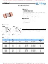
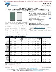
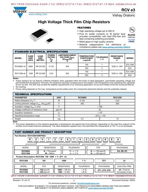
WELTRON <strong>Elektronik</strong> GmbH // Tel: 09852 6727-0 // Fax: 09852 6727-67 // E-Mail: info@weltron.dewww.vishay.com<strong>High</strong> <strong>Voltage</strong> <strong>Thick</strong> <strong>Film</strong> <strong>Chip</strong> <strong>Resistors</strong>STANDARD ELECTRICAL SPECIFICATIONSMODELCASESIZEINCHCASESIZEMETRICPOWERRATINGP 70WLIMITINGELEMENTVOLTAGE U MAX.AC RMS /DCV<strong>RCV</strong>0805 <strong>e3</strong> 0805 RR 2012M 0.125 400FEATURES<strong>RCV</strong> <strong>e3</strong>Vishay Draloric• <strong>High</strong> operating voltage (up to 500 V)• Pure tin solder contacts on Ni barrier layerprovides compatibility with lead (Pb)-free andlead containing soldering processes• Metal glaze on high quality ceramic• Material categorization: For definitions ofcompliance please see www.vishay.com/doc?99912TEMPERATURECOEFFICIENT± ppm/KTOLERANCE± %RESISTANCERANGESERIES100 1E24; E96100K to 10M200 5 E24<strong>RCV</strong>1206 <strong>e3</strong> 1206 RR 3216M 0.25 500100 1E24; E96100K to 10M200 5 E24Notes• These resistors do not feature a lifetime limitation when operated within the limits of rated dissipation, permissible operating voltage andpermissible film temperature. However, the resistance typically increases due to the resistor’s film temperature over operating time, generallyknown as drift. The drift may exceed the stability requirements of an individual application circuit and thereby limits the functional lifetime.• No marking.• Power rating depends on the max. temperature at the solder point, the component placement density and the substrate material.TECHNICAL SPECIFICATIONSPARAMETER UNIT <strong>RCV</strong>0805 <strong>RCV</strong>1206Rated dissipation P (1) 70 W 0.125 0.25Limiting element voltage U max. AC RMS /DC V 400 500Insulation voltage U ins. (1 min) V > 500<strong>Voltage</strong> coefficient of resistance chart ppm/V 25Insulation resistance > 10 9Operating temperature range °C - 55 to + 155Weight mg 5.5 10Note(1) The power dissipation on the resistors generates a temperature rise against the local ambient, depending on the heat flow support of theprinted-circuit board (thermal resistance). The rated dissipation applies only if the permitted film temperature of 155 °C is not exceeded.PART NUMBER AND PRODUCT DESCRIPTIONPart Number: <strong>RCV</strong>1206100KFKEAR C V 1 2 0 6 1 0 0 K F K E AMODEL RESISTANCE TOLERANCE TCR PACKAGING<strong>RCV</strong>0805<strong>RCV</strong>1206K = ThousandM = MillionProduct Description: <strong>RCV</strong>1206 100 100K 1 % ET1 <strong>e3</strong>F = ± 1 %J = ± 5 %K = ± 100 ppm/KN = ± 200 ppm/KEA, EB, EC<strong>RCV</strong>1206 100 100K 1 % ET1 <strong>e3</strong>MODEL TCR RESISTANCE TOLERANCE PACKAGING LEAD (Pb)-FREE<strong>RCV</strong>0805<strong>RCV</strong>1206± 100 ppm/K± 200 ppm/K100K = 100 k10M = 10 M± 1 %± 5 %ET1, ET5, ET6<strong>e3</strong> = Pure tintermination finishWELTRON <strong>Elektronik</strong> GmbH // Tel: 09852 6727-0 // Fax: 09852 6727-67 // E-Mail: info@weltron.deRevision: 12-Jul-12 1 Document Number: 20054For technical questions, contact: thickfilmchip@vishay.comTHIS DOCUMENT IS SUBJECT TO CHANGE WITHOUT NOTICE. THE PRODUCTS DESCRIBED HEREIN AND THIS DOCUMENTARE SUBJECT TO SPECIFIC DISCLAIMERS, SET FORTH AT www.vishay.com/doc?91000
WELTRON <strong>Elektronik</strong> GmbH // Tel: 09852 6727-0 // Fax: 09852 6727-67 // E-Mail: info@weltron.dewww.vishay.com<strong>RCV</strong> <strong>e3</strong>Vishay DraloricPACKAGINGMODEL CODE QUANTITY CARRIER TAPE WIDTH PITCH REEL DIAMETER<strong>RCV</strong>0805<strong>RCV</strong>1206EA = ET1 5000180 mm/7"EB = ET5 10 000 285 mm/11.25"EC = ET6 20 000 Paper tape acc. to330 mm/13"IEC 60068-3 8 mm 4 mmEA = ET1 5000 Type I180 mm/7"EB = ET5 10 000 285 mm/11.25"EC = ET6 20 000 330 mm/13"DIMENSIONSSIZEDIMENSIONS in millimetersSOLDER PAD DIMENSIONS in millimetersREFLOW SOLDERINGWAVE SOLDERINGINCH METRIC L W H T1 T2 a b l a b l0805 2012 2.0 + 0.20- 0.101206 3216 3.2 + 0.10- 0.201.25 ± 0.15 0.45 ± 0.05 0.3 + 0.20- 0.100.3 ± 0.2 0.7 1.3 1.2 0.9 1.3 1.31.6 ± 0.15 0.55 ± 0.05 0.45 ± 0.2 0.4 ± 0.2 0.9 1.7 2.0 1.1 1.7 2.3FUNCTIONAL PERFORMANCEFraction of Rated Dissipation P 70100%500Derating- 50 0 5070100 °C 150Ambient Temperature in ambWELTRON <strong>Elektronik</strong> GmbH // Tel: 09852 6727-0 // Fax: 09852 6727-67 // E-Mail: info@weltron.deRevision: 12-Jul-12 2 Document Number: 20054For technical questions, contact: thickfilmchip@vishay.comTHIS DOCUMENT IS SUBJECT TO CHANGE WITHOUT NOTICE. THE PRODUCTS DESCRIBED HEREIN AND THIS DOCUMENTARE SUBJECT TO SPECIFIC DISCLAIMERS, SET FORTH AT www.vishay.com/doc?91000
WELTRON <strong>Elektronik</strong> GmbH // Tel: 09852 6727-0 // Fax: 09852 6727-67 // E-Mail: info@weltron.dewww.vishay.com<strong>RCV</strong> <strong>e3</strong>Vishay DraloricTEST PROCEDURES AND REQUIREMENTSEN 60115-1CLAUSEIEC 60068-2TEST METHODTESTPROCEDUREStability for product types:<strong>RCV</strong> <strong>e3</strong>REQUIREMENTSPERMISSIBLE CHANGE (R)100 k to 10 M4.5 - Resistance - ± 1 % ± 5 %4.13 -Short timeoverloadU = 2.5 x P 70x R 2 x U max. ;5 s± (0.25 % R + 0.05 ) ± (0.5 % R + 0.05 )4.17.2 58 (Td) SolderabilitySolder bath method;Sn60Pb40non-activated flux;(235 ± 5) °C(2 ± 0.2) sSolder bath method;Sn96.5Ag3Cu0.5non-activated flux;(245 ± 5) °C(3 ± 0.3) sGood tinning( 95 % covered);no visible damageGood tinning( 95 % covered);no visible damage4.8.4.2 -Temperaturecoefficient(20/- 55/20) °C and(20/155/20) °C± 100 ppm/K ± 200 ppm/K4.32 21 (Uu 3 ) Shear (adhesion) 205 N No visible damage4.33 21 (Uu 1 ) Substrate bendingDepth 2 mm;3 timesNo visible damage, no open circuit in bent position± (0.25 % R + 0.05 )4.19 14 (Na)Rapid change oftemperatur<strong>e3</strong>0 min. at - 55 °C;30 min. at 125 °C5 cycles ± (0.25 % R + 0.05 ) ± (0.5 % R + 0.05 )1000 cycles ± (1 % R + 0.05 ) ± (1 % R + 0.05 )4.23 - Climatic sequence: -4.23.2 2 (Ba) Dry heat 125 °C; 16 h4.23.3 30 (Db) Damp heat, cyclic55 °C; 90 % RH24 h; 1 cycle4.23.4 1 (Aa) Cold - 55 °C; 2 h± (1 % R + 0.05 ) ± (2 % R + 0.1 )4.23.5 13 (M) Low air pressure 1 kPa; (25 ± 10) °C; 1 h4.23.6 30 (Db) Damp heat, cyclic55 °C; . 90 % RH24 h; 5 cycle4.23.7 - DC load U =P 70x R4.25.1 -Enduranceat 70 °CU = P 70x R U max. ;1.5 h on; 0.5 h off;70 °C; 1000 h ± (1 % R + 0.05 ) ± (2 % R + 0.1 )70 °C; 8000 h ± (2 % R + 0.1 ) ± (4 % R + 0.1 )4.18.2 58 (Td)Resistance tosoldering heatSolder bath method(260 ± 5) °C;(10 ± 1) s± (0.25 % R + 0.05 ) ± (0.5 % R + 0.05 )4.24 78 (Cab)Damp heat,steady state(40 ± 2) °C;(93 ± 3) % RH;56 days± (1 % R + 0.05 ) ± (2 % R + 0.05 )4.25.3 -Endurance at uppercategory temperature155 °C; 1000 h ± (1 % R + 0.05 ) ± (2 % R + 0.05 )WELTRON <strong>Elektronik</strong> GmbH // Tel: 09852 6727-0 // Fax: 09852 6727-67 // E-Mail: info@weltron.deRevision: 12-Jul-12 3 Document Number: 20054For technical questions, contact: thickfilmchip@vishay.comTHIS DOCUMENT IS SUBJECT TO CHANGE WITHOUT NOTICE. THE PRODUCTS DESCRIBED HEREIN AND THIS DOCUMENTARE SUBJECT TO SPECIFIC DISCLAIMERS, SET FORTH AT www.vishay.com/doc?91000
WELTRON <strong>Elektronik</strong> GmbH // Tel: 09852 6727-0 // Fax: 09852 6727-67 // E-Mail: info@weltron.dewww.vishay.com<strong>RCV</strong> <strong>e3</strong>Vishay DraloricTEST PROCEDURES AND REQUIREMENTSEN 60115-1CLAUSEIEC 60068-2TEST METHOD4.40 -TESTElectrostaticdischarge(human body model)PROCEDUREStability for product types:<strong>RCV</strong> <strong>e3</strong>IEC 61340-3-1;3 pos. + 3 neg. discharges;ESD voltage acc. to styleREQUIREMENTSPERMISSIBLE CHANGE (R)100 k to 10 M± (1 % R + 0.05 )4.29 45 (XA)Component solventresistanceIsopropyl alcohol;50 °C; method 2No visible damage4.30 45 (XA)Solvent resistanceof markingIsopropyl alcohol;50 °C; method 1, toothbrushMarking legible, no visible damage4.22 6 (Fc)Vibration, enduranceby sweepingf = 10 Hz to 2000 Hz;x, y, z 1.5 mm;A 200 m/s 2 ;10 sweeps per axis± (0.25 % R + 0.05 ) ± (0.5 % R + 0.05 )4.37 -Periodic electricoverloadU = 15 x P 70 x R 2 x U max.;0.1 s on; 2.5 s off;1000 cycles± (1 % R + 0.05 )4.27 -Single pulse highvoltage overload,10 μs/700 μsÛ = 10 x P 70 x R 2 x U max.;10 pulses± (1 % R + 0.05 )All tests are carried out in accordance with the following specifications:• EN 60115-1, generic specification• EN 140400, sectional specification• EN 140401-802, detail specification• IEC 60068-2-x, environmental test proceduresWELTRON <strong>Elektronik</strong> GmbH // Tel: 09852 6727-0 // Fax: 09852 6727-67 // E-Mail: info@weltron.deRevision: 12-Jul-12 4 Document Number: 20054For technical questions, contact: thickfilmchip@vishay.comTHIS DOCUMENT IS SUBJECT TO CHANGE WITHOUT NOTICE. THE PRODUCTS DESCRIBED HEREIN AND THIS DOCUMENTARE SUBJECT TO SPECIFIC DISCLAIMERS, SET FORTH AT www.vishay.com/doc?91000
WELTRON <strong>Elektronik</strong> GmbH // Tel: 09852 6727-0 // Fax: 09852 6727-67 // E-Mail: info@weltron.dewww.vishay.comLegal Disclaimer NoticeVishayDisclaimerALL PRODUCT, PRODUCT SPECIFICATIONS AND DATA ARE SUBJECT TO CHANGE WITHOUT NOTICE TO IMPROVERELIABILITY, FUNCTION OR DESIGN OR OTHERWISE.Vishay Intertechnology, Inc., its affiliates, agents, and employees, and all persons acting on its or their behalf (collectively,“Vishay”), disclaim any and all liability for any errors, inaccuracies or incompleteness contained in any datasheet or in any otherdisclosure relating to any product.Vishay makes no warranty, representation or guarantee regarding the suitability of the products for any particular purpose orthe continuing production of any product. To the maximum extent permitted by applicable law, Vishay disclaims (i) any and allliability arising out of the application or use of any product, (ii) any and all liability, including without limitation special,consequential or incidental damages, and (iii) any and all implied warranties, including warranties of fitness for particularpurpose, non-infringement and merchantability.Statements regarding the suitability of products for certain types of applications are based on Vishay’s knowledge of typicalrequirements that are often placed on Vishay products in generic applications. Such statements are not binding statementsabout the suitability of products for a particular application. It is the customer’s responsibility to validate that a particularproduct with the properties described in the product specification is suitable for use in a particular application. Parametersprovided in datasheets and/or specifications may vary in different applications and performance may vary over time. Alloperating parameters, including typical parameters, must be validated for each customer application by the customer’stechnical experts. Product specifications do not expand or otherwise modify Vishay’s terms and conditions of purchase,including but not limited to the warranty expressed therein.Except as expressly indicated in writing, Vishay products are not designed for use in medical, life-saving, or life-sustainingapplications or for any other application in which the failure of the Vishay product could result in personal injury or death.Customers using or selling Vishay products not expressly indicated for use in such applications do so at their own risk. Pleasecontact authorized Vishay personnel to obtain written terms and conditions regarding products designed for such applications.No license, express or implied, by estoppel or otherwise, to any intellectual property rights is granted by this document or byany conduct of Vishay. Product names and markings noted herein may be trademarks of their respective owners.Material Category PolicyVishay Intertechnology, Inc. hereby certifies that all its products that are identified as RoHS-Compliant fulfill thedefinitions and restrictions defined under Directive 2011/65/EU of The European Parliament and of the Councilof June 8, 2011 on the restriction of the use of certain hazardous substances in electrical and electronic equipment(EEE) - recast, unless otherwise specified as non-compliant.Please note that some Vishay documentation may still make reference to RoHS Directive 2002/95/EC. We confirm thatall the products identified as being compliant to Directive 2002/95/EC conform to Directive 2011/65/EU.Vishay Intertechnology, Inc. hereby certifies that all its products that are identified as Halogen-Free follow Halogen-Freerequirements as per JEDEC JS709A standards. Please note that some Vishay documentation may still make referenceto the IEC 61249-2-21 definition. We confirm that all the products identified as being compliant to IEC 61249-2-21conform to JEDEC JS709A standards.WELTRON <strong>Elektronik</strong> GmbH // Tel: 09852 6727-0 // Fax: 09852 6727-67 // E-Mail: info@weltron.deRevision: 02-Oct-12 1 Document Number: 91000