3DROV: A Planetary Rover System Design, Simulation and ...
3DROV: A Planetary Rover System Design, Simulation and ...
3DROV: A Planetary Rover System Design, Simulation and ...

You also want an ePaper? Increase the reach of your titles
YUMPU automatically turns print PDFs into web optimized ePapers that Google loves.
<strong>3DROV</strong>: A <strong>Planetary</strong> <strong>Rover</strong> <strong>System</strong> <strong>Design</strong>, <strong>Simulation</strong> <strong>and</strong> Verification Tool<br />
P. Poulakis (1) , L. Joudrier (1) , S. Wailliez (2) , K.Kapellos (2)<br />
(1) European Space Agency, ESTEC/Automation & Robotics Section<br />
{pantelis.poulakis , luc.joudrier}@esa.int<br />
(2) Trasys Space<br />
{sebastien.wailliez, konstantinos.kapellos}@trasys.be<br />
Abstract<br />
This paper presents the ongoing work on the<br />
<strong>3DROV</strong> planetary rover system simulation<br />
environment. <strong>3DROV</strong> is designed for end-to-end<br />
mission simulations. It includes models of the<br />
planetary environment, the mechanical, electrical, <strong>and</strong><br />
thermal subsystems of the rover, generic onboard<br />
controller, <strong>and</strong> a ground control station module.<br />
Different levels of fidelity exist for the physical models<br />
depending on the scope of the simulation <strong>and</strong> scientific<br />
instrument models are included for simulating science<br />
mission scenarios. <strong>3DROV</strong> offers the ability to attach<br />
onboard algorithms for testing. The simulation<br />
framework relies on ESA’s SIMSAT 4.0 <strong>and</strong> the models<br />
are designed to comply with the SMP 2.0 st<strong>and</strong>ard.<br />
For modeling the rover’s physical subsystems the<br />
novel port-based modeling approach was adopted.<br />
1. Introduction<br />
The operations of planetary robotic agents need to<br />
be taken into account early in the system design phase,<br />
due to the variety of tasks <strong>and</strong> conditions that may be<br />
encountered. The difficulty of designing <strong>and</strong> testing a<br />
planetary rover is to a big extent due to the lack of<br />
knowledge <strong>and</strong> reproduction capabilities of the target<br />
environment, which often ends up being the driving<br />
factor of the design.<br />
<strong>Rover</strong>s are key elements to European planetary<br />
exploration missions, with ESA’s ExoMars due to<br />
launch in 2013 <strong>and</strong> NEXT technology demonstration<br />
mission to the Lunar South Pole in the conceptual<br />
design phase. Thus there is a significant need for the<br />
development of a simulation environment that supports<br />
the system design process <strong>and</strong> provides a virtual<br />
verification testbed. A similar effort has been ongoing<br />
at JPL for several years, resulting in the ROAMS<br />
<strong>Planetary</strong> <strong>Rover</strong> <strong>Simulation</strong> Environment [3],[4].<br />
ROAMS has been used very successfully in NASA’s<br />
Mars Exploration <strong>Rover</strong> (MER) mission, in both the<br />
development <strong>and</strong> operations phases <strong>and</strong> is already<br />
being used for the upcoming Mars Science Laboratory<br />
(MSL) mission.<br />
In this paper we describe the status of the newly<br />
established <strong>3DROV</strong> research activity which aims at the<br />
development of a generic tool that supports the testing<br />
<strong>and</strong> verification at system level of planetary robot<br />
missions. The <strong>3DROV</strong> activity has been initiated by<br />
the Automation & Robotics Section of ESA with<br />
Trasys Space, Belgium as the prime industrial<br />
contractor.<br />
As the work in <strong>3DROV</strong> is ongoing, we present the<br />
current status of the project <strong>and</strong> the future development<br />
<strong>and</strong> validation plans. The structure of the paper is as<br />
follows. Section 2 gives an overview of the design<br />
philosophy <strong>and</strong> high-level architecture of <strong>3DROV</strong>. In<br />
section 3 the chosen simulation framework, SIMSAT,<br />
is described. Section 4 is devoted to the rover physical<br />
subsystem (s/s) models, while section 5 presents the<br />
modeling of scientific instruments within <strong>3DROV</strong>.<br />
Subsequently the design of the Generic Controller is<br />
described in section 6 <strong>and</strong> section 7 focuses on the<br />
developments on the Environment model. Section 8 is<br />
devoted to the Control Station <strong>and</strong> the Visualization<br />
environment of <strong>3DROV</strong>. The last two sections of the<br />
paper present preliminary results of the system <strong>and</strong><br />
validation plans <strong>and</strong> offer a brief discussion<br />
respectively.<br />
2. <strong>3DROV</strong> design<br />
The first section of this paragraph describes in the<br />
design philosophy <strong>and</strong> the goals that drive the<br />
development of <strong>3DROV</strong>. Subsequently the architecture<br />
is presented at system level together with a functional<br />
overview of the main elements.
2.1 <strong>Design</strong> philosophy<br />
The driving philosophy behind the project is to<br />
build a tool for rover system design <strong>and</strong> simulation that<br />
would provide ESA’s Automation & Robotics section<br />
the means to effectively support the development of<br />
European planetary exploration missions. More<br />
specific design requirements of <strong>3DROV</strong> include the<br />
following:<br />
Generic end-to-end simulation capabilities. For<br />
assessing the design on a system or mission level, the<br />
<strong>3DROV</strong> environment must be flexible <strong>and</strong> generic. It<br />
must be able to simulate a mission scenario from the<br />
early stage of its definition until its completion. Thus it<br />
is essential to have the capability to incorporate models<br />
of scientific instruments interacting with the virtual<br />
environment to simulate the daily scientific outputs of<br />
a given scenario. Finally, it is within the scope of<br />
<strong>3DROV</strong> to represent <strong>and</strong> support different planetary<br />
environments (Moon <strong>and</strong> Mars).<br />
Utilize ESA simulation framework <strong>and</strong> st<strong>and</strong>ardized<br />
model interfaces. In order to take advantage of the<br />
technology <strong>and</strong> know-how developed within the<br />
Agency on spacecraft simulations, it was decided to<br />
adopt the SIMSAT 4.0 framework [1]. Developed at<br />
the European Space Operation Center (ESOC) in<br />
collaboration with European industry, SIMSAT is used<br />
for spacecraft <strong>and</strong> ground segment simulations <strong>and</strong><br />
training. To be used within this framework, the models<br />
under development for <strong>3DROV</strong> must comply with the<br />
<strong>Simulation</strong> Modeling Portability 2.0 st<strong>and</strong>ard (SMP<br />
2.0). This st<strong>and</strong>ard was introduced by ESA to aid the<br />
portability of simulation models developed within the<br />
European Space Industry. The above choices also aim<br />
at making the <strong>3DROV</strong> infrastructure compatible with<br />
other groups within ESA (e.g, Operations, the<br />
Concurrent <strong>Design</strong> Facility, etc.).<br />
Different levels of fidelity for multi-domain physical<br />
system models. An important requirement is that<br />
<strong>3DROV</strong> can provide high fidelity dynamic simulations<br />
for the rover physical subsystems but also include the<br />
option to use low fidelity models for fast, mission level<br />
simulation runs. The rover physical models must<br />
include the mechanical, power <strong>and</strong> thermal s/ss as<br />
well, <strong>and</strong> also a dynamically consistent contact model.<br />
The novel port-based methodology has been chosen<br />
for the rover physics-based models, which provides an<br />
intuitive energetic model structure both within <strong>and</strong><br />
between the different domains.<br />
<strong>System</strong> testbench approach. As a tool, <strong>3DROV</strong> is also<br />
meant to be utilized as a testbench for onboard<br />
controllers <strong>and</strong> ground station modules. It should<br />
support hardware in the loop simulation allowing<br />
further use with breadboards <strong>and</strong> engineering models.<br />
Thus it is required that <strong>3DROV</strong> has a modular<br />
architecture with clear interfaces to ease closing the<br />
loop with test modules.<br />
2.2 <strong>System</strong> architecture<br />
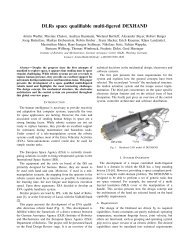
<strong>3DROV</strong> is designed for Linux <strong>and</strong> VxWorks<br />
operating systems. Its main building blocks <strong>and</strong> a highlevel<br />
interconnection can be visualized in<br />
Figure 1. An overview of the functionality <strong>and</strong> role<br />
of each block within the <strong>3DROV</strong> architecture is given<br />
below.<br />
Figure 1. <strong>3DROV</strong> building blocks<br />
The <strong>Simulation</strong> Framework relies on ESA’s SIMSAT<br />
<strong>and</strong> is responsible for the proper execution <strong>and</strong><br />
scheduling of the simulation run.<br />
The Control Station serves as the virtual rover’s<br />
ground control station. It provides the means to set-up<br />
mission scenarios via a 3D graphical environment <strong>and</strong><br />
upload them to the rover while also assigned to display<br />
the onboard telemetry. The robotic ground control<br />
station A-DREAMS [2] has been chosen as the<br />
baseline for <strong>3DROV</strong>.<br />
The Generic Controller assumes the role of the<br />
onboard flight software, as a SIMSAT component, <strong>and</strong><br />
controls all the rover operations. Algorithms or<br />
software modules can be attached on the Generic<br />
Controller – or replace it completely – for testing in the<br />
virtual environment.<br />
<strong>Rover</strong> s/s block includes models of rover physical s/ss,<br />
sensors <strong>and</strong> scientific instruments. Although developed<br />
in different modeling environments they comprise
C/C++ code encapsulated in SMP-2.0-compliant<br />
SIMSAT modules.<br />
The Environment component is responsible for the<br />
ephemeris <strong>and</strong> timekeeping of the system, for<br />
generating terrain <strong>and</strong> atmospheric conditions, <strong>and</strong> for<br />
tracking the rover location. Within the framework it<br />
interfaces with most of the rover submodels (contact<br />
model, thermal model, etc.) to provide them with the<br />
necessary environmental information.<br />
The Visualization Environment acts as the front-end of<br />
<strong>3DROV</strong>, providing real-time visualization of the<br />
simulation run <strong>and</strong> also visualization within the<br />
Control Station to assist the preparation of Activities.<br />
3. <strong>Simulation</strong> framework<br />
One of the initial design choices of the <strong>3DROV</strong><br />
project was to incorporate the ESA developed<br />
SIMSAT simulation framework, version 4.0. SIMSAT<br />
comprises of the following elements:<br />
The SIMSAT Man-Machine Interface (MMI). This<br />
provides the interface between the user <strong>and</strong> the<br />
simulator. The MMI is used to build-up the simulator<br />
as a set of interconnected components, to control the<br />
evolution of the execution (start/stop, save states, etc.)<br />
<strong>and</strong> to monitor its internal parameters.<br />
The SIMSAT Kernel. The kernel is the ‘engine’ of the<br />
simulator, thus taking care of the low level tasks such<br />
as creating <strong>and</strong> running processes, storing <strong>and</strong> reading<br />
data, etc. The kernel is also responsible for st<strong>and</strong>ard<br />
simulation services such as message logging,<br />
scheduling of events <strong>and</strong> time management.<br />
Models. This element includes the models to be<br />
executed within the framework. For <strong>3DROV</strong> these<br />
include the Generic Controller, the <strong>Rover</strong> models <strong>and</strong><br />
the Environment. SIMSAT integrates the models via<br />
the SMP 2.0 interface st<strong>and</strong>ard.<br />
4. Models of physical systems<br />
For the goals of <strong>3DROV</strong> considerable effort is put<br />
in the development of consistent <strong>and</strong> modular models<br />
for the physical systems of a rover. Using a port-based,<br />
lumped-parameter approach we model the mechanical<br />
subsystems (s/ss) <strong>and</strong> the wheel-terrain interaction as<br />
well as the thermal <strong>and</strong> power s/ss of a rover. Two<br />
levels of abstraction exist for the rover models within<br />
<strong>3DROV</strong>: a) a detailed dynamic model of the whole<br />
system where each domain can be plugged in or left<br />
out of a simulation run <strong>and</strong> b) a purely kinematical one<br />
for fast, operation-level simulations.<br />
4.1 Modeling methodology<br />
Physical systems interact via a bidirectional<br />
interconnection comprised of generalized forces <strong>and</strong><br />
generalized velocities. The signal modeling approach<br />
is not suitable to capture this structure intuitively, since<br />
every interconnection carries only one signal. Using<br />
the port-based approach, however, models of physical<br />
systems interact via bidirectional ports which<br />
simultaneously carry effort <strong>and</strong> flow variables, the<br />
product of which represents the power exchange. This<br />
approach offers a systematic as well as intuitive way of<br />
modeling <strong>and</strong> results in a unified way to represent <strong>and</strong><br />
interconnect subsystems from different physical<br />
domains such as mechanical, electrical, thermal, etc.<br />
Rigid body motions are described using Screw<br />
Theory [5], which gives the advantage of expressing<br />
the velocities of bodies geometrically (i.e., coordinate<br />
free) by their respective twists. Generalized forces<br />
acting on the bodies are defined through wrenches.<br />
The dynamics of the mechanical subsystems are<br />
expressed in the port-Hamiltonian framework, where<br />
positions <strong>and</strong> momenta are used as state variables. The<br />
port-Hamiltonian representation gives an intuitive<br />
representation of the energetic structure of a system<br />
[6].<br />
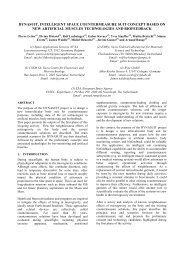
The commercial tool 20sim [7] is used as the<br />
modeling environment for the rover’s physical<br />
subsystems. It inherently supports both the signal <strong>and</strong><br />
the port-based modeling approach <strong>and</strong> thus offers the<br />
possibility to build hybrid models from different<br />
physical domains. 20sim exports the models in C-code<br />
together with the integration method (see Figure 2).<br />
The exported models are attached to the SIMSAT<br />
simulation framework via the SMP-2.0-compliant<br />
interface.<br />
Figure 2. <strong>Rover</strong> s/s models
4.2 Mechanical s/s models<br />
In the current phase of the development of <strong>3DROV</strong><br />
the rover mechanics are modeled within 20sim’s 3D<br />
Editor Toolbox. The mechanical configuration is<br />
defined graphically <strong>and</strong> CAD data is attached to it for<br />
visualization. The rover’s kinematics <strong>and</strong> dynamics<br />
equations are then exported as a 20sim code block,<br />
with power-port interfaces for the actuated parts,<br />
where it is combined with other s/s models. This<br />
process is time consuming when rover mechanical<br />
parameters need to be modified or other mobility<br />
concepts need to be tested, <strong>and</strong> a more generic <strong>and</strong><br />
simplistic approach will be sought in the next phase of<br />
the project.<br />
One important feature of 20sim is that it offers<br />
several methods to h<strong>and</strong>le closed-loop mechanisms,<br />
which makes it very generic for the types of mobility<br />
configurations that we can model.<br />
4.3 Power <strong>and</strong> Thermal s/s models<br />
The core of the power s/s model is the solar panel<br />
models <strong>and</strong> battery models. Applying the power-port<br />
based approach, in the electrical domain, we can attach<br />
models of different levels of fidelity for the power s/s,<br />
depending on the simulation needs. Instruments are<br />
modeled as loads on the electrical network, based on<br />
their nominal consumption characteristics.<br />
The thermal models used within <strong>3DROV</strong> are<br />
derived by simplifying large thermal analysis models<br />
of specific rover configurations. The reference thermal<br />
model under development for <strong>3DROV</strong> aims at<br />
reducing the complex thermal analysis model for the<br />
current configuration of the ExoMars rover to a 30node<br />
model. Expressed in the lumped-parameter<br />
fashion, the nodes of the reduced model represent an<br />
average thermal behavior of the components that the<br />
node includes. The thermal model interfaces (powerports<br />
with the rest of the physical model <strong>and</strong> signals<br />
with <strong>3DROV</strong>’s environment mode) are designed so<br />
that the model can be exchanged with a more<br />
sophisticated one.<br />
4.4 Actuators – Sensors<br />
A high fidelity actuator model within <strong>3DROV</strong><br />
describes in a lumped-parameter way the dynamics of<br />
the respective s/s. This extends to modeling the lowlevel<br />
servo controller of the motor, the transmission<br />
system, its electrical circuit <strong>and</strong> its thermal behavior.<br />
<strong>3DROV</strong> models the functionality <strong>and</strong> signal<br />
processing behavior of sensors neglecting their<br />
physical characteristics (mass, power consumption)<br />
since this would not improve significantly the fidelity<br />
of the system. Thus sensors are modeled as signal<br />
processing blocks that transduce the input magnitude<br />
to a measurement magnitude, allowing the modeler to<br />
include algorithms that induce errors to the outputs.<br />
Sensors modeled within <strong>3DROV</strong> include common<br />
space robotic sensors such as encoders, potentiometers,<br />
temperature sensors, inertial measurement units<br />
(IMUs) <strong>and</strong> sun sensors.<br />
4.5 Contact model<br />
The first instance of the <strong>3DROV</strong> contact model,<br />
currently implemented, assumes the wheels <strong>and</strong> terrain<br />
to be smooth surfaces with orthogonal<br />
parameterizations f(θ,φ) <strong>and</strong> g(u,v). One pair of contact<br />
points is assumed per wheel. Deriving the differential<br />
geometry parameters, namely the metric M, the<br />
curvature K, <strong>and</strong> the torsion T, for each surface patch<br />
we can detect <strong>and</strong> track the wheel-terrain contact<br />
points using contact kinematics equations, as described<br />
in [8]. The ongoing work on the contact model aims at<br />
making it more generic in the terrain surface utilization<br />
by incorporating computational geometry algorithms<br />
for collision detection.<br />
The contact model is also responsible of inducing<br />
forces in the normal direction <strong>and</strong> on the tangential<br />
plane defined by each pair of wheel-terrain contact<br />
points. During simulation the normal forces are<br />
computed numerically using a physically-based<br />
gradient method. In the normal direction of each pair<br />
of contact points a 1 degree of freedom (DoF) Kelvin-<br />
Voigt compliant system is attached (Eq. 1), where Fn is<br />
the normal force, zG penetration depth, kn <strong>and</strong> dn the<br />
spring-damper coefficients. This technique is causal<br />
<strong>and</strong> very efficient for a multibody dynamic simulator,<br />
at the expense of adding one more state per wheel to<br />
the system.<br />
F = k z + d z&<br />
(1)<br />
n<br />
n<br />
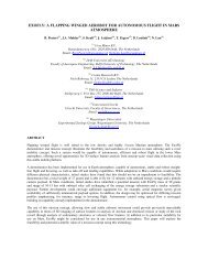
The forces on the tangential contact plane are<br />
calculated in a similar manner, as shown in<br />
Figure 3. Each compliant system has, as a saturation<br />
threshold, the maximum shear capacity of the soil in<br />
the longitudinal direction, given by the terramechanic<br />
(Eq. 2). Above this threshold the wheel starts to slip.<br />
Parameters c <strong>and</strong> φ are soil cohesion <strong>and</strong> friction angle<br />
respectively, <strong>and</strong> A is the wheel-terrain contact area.<br />
G<br />
n<br />
G
F = cA + F tanφ<br />
(2)<br />
Y max n<br />
The reason for decoupling the two directions is to<br />
be able to tune the system parameters separately for<br />
tests. This simplified hybrid contact model performs<br />
well in a multibody simulator, nevertheless it is part of<br />
the ongoing work in <strong>3DROV</strong> to incorporate more<br />
terramechanics effects.<br />
Figure 3. Tangential contact model<br />
5. Scientific instrument models<br />
The instrument models provide a virtual presence of<br />
the rover payloads with respect to data acquisition,<br />
sensor system response properties, <strong>and</strong> payload data<br />
generation including onboard processing.<br />
The <strong>3DROV</strong> infrastructure allows instantiation of<br />
virtual instruments <strong>and</strong> provides the needed structures<br />
<strong>and</strong> real-time mechanisms to integrate <strong>and</strong> execute data<br />
acquisition <strong>and</strong> data product generation algorithms. It<br />
also provides access to the global state of the simulator<br />
<strong>and</strong> in particular the rover state, information needed<br />
for data registration of the scientific measurement. The<br />
instances of the virtual instrument execute comm<strong>and</strong>s<br />
issued by the Generic Controller <strong>and</strong> their states are<br />
sampled in discrete time steps. Thus the operation<br />
behavior of the instrument is monitored <strong>and</strong> can be<br />
acquired by the other subsystems of the simulator.<br />
6. Generic controller<br />
The role of the Generic Controller is to substitute<br />
the rover on-board flight software in the simulator<br />
environment. It receives <strong>and</strong> executes the Activity<br />
Plans as prepared <strong>and</strong> uploaded by the Ground Control<br />
Station <strong>and</strong> transmits back housekeeping <strong>and</strong> science<br />
data. To this end, it interfaces with:<br />
• The rover s/s models for the simulation of the<br />
Activities related to the locomotion, the<br />
communication, the power <strong>and</strong> the thermal s/ss<br />
management.<br />
• The Instrument models for the simulation of<br />
science related Activities.<br />
The Generic Controller functions as an SMP-2.0compliant<br />
module within SIMSAT. It implements a<br />
three-layer <strong>Rover</strong> control architecture ([9],[10],[11])<br />
with the hybrid nature of combining both continuous<br />
<strong>and</strong> discrete event aspects, as shown in<br />
Figure 4.<br />
<strong>3DROV</strong>’s controller module captures these aspects<br />
considering two main entities: the Actions <strong>and</strong> the<br />
Tasks which are elements of the Functional <strong>and</strong> the<br />
Executive level respectively.<br />
The Action represents an elementary robotic activity<br />
<strong>and</strong> encapsulates a control law into a logical behaviour<br />
that determines the instants of its activation, its end or<br />
the occurrence of exceptions.<br />
The Task is a logical <strong>and</strong> temporal composition of<br />
actions or tasks, to achieve an objective in a context<br />
dependent <strong>and</strong> reliable way. Therefore, the Task can be<br />
considered as a discrete-event controller which<br />
rhythms the sequencing of actions (through their<br />
respective local event-based controllers) following a<br />
user-defined scheme. The event-based behaviour<br />
constitutes the interface of an Action to a Task.<br />
Figure 4. Generic controller architecture<br />
The Actions of the Generic Controller are in<br />
principle fixed, but take all necessary dispositions to<br />
allow the operator to fine tune parameters of the<br />
involved algorithms as well as introduce new<br />
algorithms. Consequently, algorithms developed for<br />
rover flight controllers can be integrated to the<br />
<strong>3DROV</strong> Generic Controller for testing.
7. Environment model<br />
This <strong>3DROV</strong> model introduces the environmental<br />
conditions in which a planetary rover operates with<br />
respect to locomotion, energy, communications, <strong>and</strong><br />
science activities. It supports other <strong>3DROV</strong> models by<br />
providing them with environmental data.<br />
The model is designed to be generic <strong>and</strong><br />
configurable so that a wide range of rover missions<br />
with various scientific payloads can be supported. The<br />
components which comprise <strong>3DROV</strong>’s Environment<br />
model are presented in the following subsections.<br />
7.1 Geographical Information <strong>System</strong> (GIS)<br />
component<br />
The GIS component concentrates geographic <strong>and</strong><br />
spatial data in a repository of so-called “locations”.<br />
Locations contain geometrically co-registered datasets:<br />
Digital Elevation Models (DEMs), terramechanical<br />
maps, orbital images <strong>and</strong> other types of terrain<br />
overlays. As such, the <strong>3DROV</strong> GIS mainly serves as a<br />
back-end to the Terrain component (see 7.2) as well as<br />
an imagery server that supports camera <strong>and</strong> scientific<br />
imager models.<br />
The component design relies on the open source<br />
GRASS GIS [12], where the locations are created or<br />
edited offline. With GRASS we can synthesize DEMs<br />
<strong>and</strong> also import <strong>and</strong> interpolate planetary DEMs (e.g.<br />
MOLA) or synthetic DEMs (e.g. from PANGU [13]).<br />
7.2 Terrain component<br />
This <strong>3DROV</strong> component answers queries from<br />
other simulation modules for information about the<br />
relief <strong>and</strong> terramechanical properties of the planetary<br />
terrain. The wheel-terrain contact model is a prime<br />
example of this. Relief is extracted from a DEM, while<br />
mechanical properties are derived from a databaselinked<br />
terramechanical map. In this latter map, patches<br />
of terrain have been assigned soft or hard soil types (<br />
Figure 5) <strong>and</strong> various rock coverage, all of which<br />
are mechanically parameterized.<br />
The Terrain component is also designed to provide<br />
scientific telemetry –raw or processed– for the<br />
simulation of the relevant rover payloads. It is<br />
developed upon the PostgreSQL database <strong>and</strong> its<br />
PostGIS spatial extension [14].<br />
7.3 Orbital <strong>and</strong> Timekeeping component<br />
The Orbital <strong>and</strong> Timekeeping module keeps track of<br />
solar, planetary <strong>and</strong> orbiter ephemerides, line of sight<br />
conditions, <strong>and</strong> solar time. It is typically used by the<br />
solar panel model, to retrieve solar angles, by the<br />
onboard radio communication software to retrieve<br />
rover-orbiter or orbiter-Earth viewing geometry <strong>and</strong><br />
communication lags. The component is based on the<br />
NASA/NAIF Spice Toolkit [12].<br />
Figure 5. Terramechanical map in GRASS<br />
7.4 Atmosphere component<br />
This environment component provides data on the<br />
planetary atmospheric conditions: wind speed,<br />
atmospheric dust, solar flux, ambient temperature,<br />
surface temperature, etc. These magnitudes are<br />
essential for other <strong>3DROV</strong> modules such as the<br />
instruments, the thermal s/s models, <strong>and</strong> the solar panel<br />
models. Due to the fact that planetary atmospheres are<br />
unique this component is the least generic of the four<br />
that make up the <strong>3DROV</strong> Environment Model. The<br />
Martian atmosphere is supported by the Mars Climate<br />
Database [15], which is dynamic <strong>and</strong> scenario-driven.<br />
A simplified atmospheric model describes the Moon<br />
conditions.<br />
8. Control station & Visualization<br />
environment<br />
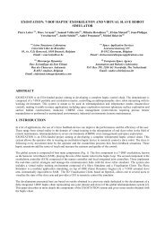
The <strong>3DROV</strong> Control Station simulates the basic<br />
functionalities of a mission Ground Control Station. It<br />
is based on the ESA A-DREAMS Robotic Ground<br />
Control Station [2] (see Figure 6), with the following<br />
functionalities:<br />
Telemetry (TM) acquisition <strong>and</strong> processing: Receiving<br />
TM packets from the Generic Controller (or batch<br />
downloaded data) <strong>and</strong> processing them to the<br />
appropriate level to generate products for further<br />
analysis.
<strong>Rover</strong> housekeeping data monitoring <strong>and</strong> assessment,<br />
for monitoring the rover s/ss behavior during<br />
simulation <strong>and</strong> post-analysis.<br />
Science data monitoring <strong>and</strong> assessment, for science<br />
products analysis. The operator can analyze selected<br />
imagery <strong>and</strong> instruments products on dedicated MMIs,<br />
in order to identify potential scientific targets to be<br />
used in the following Activity Plan.<br />
Activity preparation, validation <strong>and</strong> telecomm<strong>and</strong><br />
(TC), for the specification <strong>and</strong> formal verification of<br />
the Activity Plans to be uploaded to the Generic<br />
Controller. Activity Plans are defined as timelines of<br />
Tasks.<br />
The visualization environment is used both for<br />
visualizing independently in 3D the evolution of the<br />
simulation <strong>and</strong> as an integrated component of the<br />
Control Station.<br />
<strong>3DROV</strong>’s visualization environment renders in a<br />
photorealistic virtual scene the simulated rover <strong>and</strong> its<br />
surrounding environment in the form of meshes. It<br />
visualizes additional items such as ‘targets’, Activity<br />
glyphs <strong>and</strong> image overlays <strong>and</strong> generates the animation<br />
of all modeled mechanisms based on the rover state<br />
values issued by the SIMSAT framework. Shadows<br />
cast by the illumination sources are displayed <strong>and</strong><br />
ambient conditions are tuned to adjust direct sunlight<br />
intensity <strong>and</strong> direction, ambient light <strong>and</strong> surface<br />
reflexivity characteristics according to conditions<br />
published by the Environment model.<br />
The main technologies <strong>and</strong> tools used for the 3D<br />
Visualization environment include material <strong>and</strong><br />
composition scripting, advanced scene managing,<br />
meshes support, resources manager, <strong>and</strong> XML loaders.<br />
Figure 6. The A-DREAMS control station<br />
9. Preliminary results <strong>and</strong> applications<br />
<strong>3DROV</strong> is a newly established research activity<br />
within the Automation & Robotics section of ESA. Up<br />
to now significant work has been conducted on the<br />
development of individual <strong>3DROV</strong> components with<br />
the focus moving to integration. Preliminary results of<br />
the project include the following.<br />
A consistent <strong>and</strong> validated modeling approach has<br />
been taken for the modeling of the rover physical s/ss.<br />
Extensive modeling work has been performed on rover<br />
locomotion s/ss –as preliminary work on <strong>3DROV</strong>–<br />
with application to the c<strong>and</strong>idate chassis configurations<br />
for the ExoMars mission. These models were<br />
simulated for chassis performance evaluations <strong>and</strong><br />
focused on static stability issues. Results are well<br />
documented in [8].<br />
The <strong>3DROV</strong> concept of hardware in the loop was<br />
demonstrated during the ASTRA 2006 workshop at<br />
ESTEC. The Generic Controller, specified in section 6,<br />
was installed onboard the ExoMars Demonstration<br />
<strong>Rover</strong> (ExoMaDer) of the Automation & Robotics Lab<br />
(ARL). The CNES <strong>Rover</strong> Autonomous Navigation<br />
Software [16] was attached to the Controller <strong>and</strong><br />
mission targets were defined from the Control Station.<br />
The experiment was conducted towards the functional<br />
verification of the individual components to be used in<br />
<strong>3DROV</strong> <strong>and</strong> the validation of hardware-in-the-loop<br />
system interfaces.<br />
In addition to this work, the effort of building a<br />
scientific instrument library, for the simulation needs<br />
of <strong>3DROV</strong>, is in progress. Up to date the library<br />
contains models for: the Mars Infrared Mapper<br />
(MIMA), the WISDOM Ground Penetrating Radar, the<br />
Close-Up Imager (CLUPI) <strong>and</strong> the Miniaturized<br />
Moessbauer Spectrometer (MIMOS II).<br />
10. Ongoing development<br />
The development of the <strong>3DROV</strong> is ongoing<br />
towards a complete <strong>and</strong> extendable simulation <strong>and</strong><br />
verification environment.<br />
One of the main areas of focus of the ongoing work<br />
is the development of a generic contact model. While<br />
the current contact model is dynamically consistent<br />
<strong>and</strong> efficient, the implemented contact tracking method<br />
restricts us to using smooth, parameterized terrain<br />
surfaces. Currently a new contact model is designed<br />
with the goal to be generic in the types of surfaces it<br />
can h<strong>and</strong>le <strong>and</strong> also provide contact dynamics<br />
consistency in the simulation.<br />
In parallel to the development of <strong>3DROV</strong> a<br />
complete rover system testbench is being set up at the
ARL. It is comprised of the indoors planetary terrain<br />
surface (aprox. 81m 2 ), a Vicon global motion tracking<br />
system [17] <strong>and</strong> several rover prototype designs.<br />
Moreover, a Single Wheel Testbed (SWT), built by<br />
DLR, has been installed in the lab for the performance<br />
measurements of rover wheel designs. Among other<br />
utilization, the above systems will aid our upcoming<br />
verification efforts for the <strong>3DROV</strong> components. It is<br />
planned to use the SWT for the verification of <strong>and</strong> fine<br />
tuning of the new contact model under development.<br />
11. Conclusions<br />
This paper presents an overview of the current<br />
status of the recently initiated <strong>3DROV</strong> activity. Upon<br />
completion it will provide the necessary infrastructure<br />
to evaluate robotic systems for planetary exploration<br />
missions <strong>and</strong> generate design feedback.<br />
Currently the work focuses on the completion of<br />
individual components within the environment as well<br />
as their integration. Significant effort is also put in<br />
planning system validation methods.<br />
<strong>3DROV</strong> aims at providing a valuable tool to the<br />
Automation & Robotics section of ESA towards<br />
support activities to future European planetary<br />
exploration missions, with specific view on the<br />
ExoMars mission.<br />
12. References<br />
[1] “Introduction to Simsat.”,<br />
URL: http://www.egos.esa.int/portal/egosweb/products/Simulators/SIMSAT/,<br />
Dec 2007.<br />
[2] F. Didot, K. Kapellos, A. Schielle, “A-DREAMS: An<br />
Advanced Ground Control Station for Teleoperation <strong>and</strong><br />
Telemanipulation”, in 8 th ESA Workshop on Advanced Space<br />
Technologies for Robotics <strong>and</strong> Automation (ASTRA’04),<br />
Noordwijk, The Netherl<strong>and</strong>s, 2004.<br />
[3] A. Jain et.al. “ROAMS: <strong>Planetary</strong> surface rover<br />
simulation environment”, in 7 th Int. Symposium on Artificial<br />
Intelligence <strong>and</strong> Automation in Space (iSAIRAS 2003), Nara,<br />
Japan, May 19-23, 2003.<br />
[4] A. Jain et.al. “Recent developments in the ROAMS<br />
planetary rover simulation environment”, in IEEE Aerospace<br />
Conference, Big Sky, Montana, USA, Mar. 6-13, 2004.<br />
[5] S. Stramigioli, H. Bruyninckx, “Geometry <strong>and</strong> screw<br />
theory for robotics”, Tutorial from International Conference<br />
for Robotics <strong>and</strong> Automation (ICRA), IEEE/RSJ, Seoul,<br />
Korea, 2001.<br />
[6] Shaft, A.v.d., L 2-Gain <strong>and</strong> passivity techniques in nonlinear<br />
control, ser. Communication <strong>and</strong> Control<br />
Engineering, Springer-Verlag, 2001.<br />
[7] “20sim Modeling <strong>and</strong> <strong>Simulation</strong> Tool.”, URL:<br />
http://www.20sim.com., Dec 2007.<br />
[8] P. Poulakis, L. Joudrier, S. Stramigioli, “Port-based<br />
modelling <strong>and</strong> simulation of planetary rover locomotion on<br />
rough terrain”, in 9 th ESA Workshop on Advanced Space<br />
Technologies for Robotics <strong>and</strong> Automation (ASTRA’06),<br />
Noordwijk, The Netherl<strong>and</strong>s, 2006.<br />
[9] D. Simon et.al., “Computer-aided design of a generic<br />
robot controller”, Transactions on Control <strong>System</strong>s<br />
Technology, IEEE, Vol.1, Issue: 4, Dec. 1993.<br />
[10] K. Kapellos et.al., “Task Level Specification <strong>and</strong><br />
Formal Verification of Robotics Control <strong>System</strong>s”,<br />
International Journal of <strong>System</strong>s Science, Taylor & Francis<br />
Vol.30, Num.11, Nov. 1999.<br />
[11] K. Kapellos et.al. “The Orccad Robot Control<br />
Architecture <strong>and</strong> Tools in Space Applications”, in 9 th ESA<br />
Workshop on Advanced Space Technologies for Robotics <strong>and</strong><br />
Automation (ASTRA’06), Noordwijk, The Netherl<strong>and</strong>s, 2006.<br />
[12] Neteler, M., Mitasova, H., Open Source GIS: A<br />
GRASS GIS Approach, Springer, New York, November<br />
2007. URL: http://grass.itc.it/.<br />
[13] S. M. Parkes et.al. “Planet surface simulation with<br />
PANGU”, in 8 th International Conference on Space<br />
Operations (SpaceOps 2004), Montreal, Canada, May 17-21,<br />
2004.<br />
[14] “PostgreSQL Database <strong>and</strong> its PostGIS spatial<br />
extension”, URL: http://www.postgresql.org,<br />
http://postgis.refractions.net, Dec 2007.<br />
[15] S. J. Bingham et.al., “The Mars Climate Database”,<br />
Proceedings of the 1 st International Workshop on Mars<br />
Atmosphere Modelling <strong>and</strong> Observations, Granada, Spain,<br />
13-15 Jan 2003.<br />
[16] M. Maurette, “Mars <strong>Rover</strong> Autonomous Navigation”,<br />
Journal of Autonomous Robots, Springer Netherl<strong>and</strong>s,<br />
Vol.14, Numbers 2-3, pp. 199-208, Nov 01, 2004.<br />
[17] “Vicon Motion Tracking <strong>System</strong>s.”, URL:<br />
http://www.vicon.com., Dec 2007.