


Create successful ePaper yourself
Turn your PDF publications into a flip-book with our unique Google optimized e-Paper software.
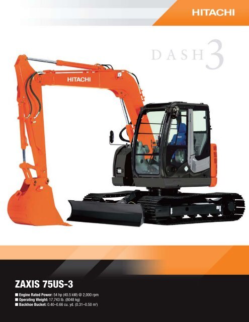
<strong>ZAXIS</strong> <strong>75US</strong>-3<br />
n Engine Rated Power: 54 hp (40.5 kW) @ 2,000 rpm<br />
n Operating Weight: 17,743 lb. (8048 kg)<br />
n Backhoe Bucket: 0.40–0.66 cu. yd. (0.31–0.50 m 3 )
<strong>ZAXIS</strong> <strong>75US</strong>-3 SPECIFICATIONS<br />
Engine<br />
Manufacturer and Model.........................................................Isuzu 4LE2X<br />
Non-Road Emission Standards................................................certified to EPA interim Tier-4 emissions<br />
Net Power (ISO9249)...............................................................54 hp (40.5 kW) @ 2,000 rpm<br />
Cylinders.................................................................................4<br />
Displacement..........................................................................133 cu. in. (2.2 L)<br />
Off-Level Capacity...................................................................70% (35 deg.)<br />
Aspiration................................................................................turbocharged with intercooler<br />
Cooling<br />
Variable-speed fan directly driven by the engine through a linear clutch; nonreversible<br />
Powertrain<br />
Two-speed propel with automatic shift<br />
Maximum Travel Speed<br />
Low ..................................................................................1.9 mph (3.1 km/h)<br />
High .................................................................................3.1 mph (5.0 km/h)<br />
Hydraulics<br />
Open center, load sensing<br />
Main Pumps .........................................................................3 variable-displacement axial piston<br />
Maximum Rated Flow .......................................................2 x 20.9 gpm + 16.3 gpm (2 x 79.2 L/m + 61.6 L/m)<br />
Pilot Pump ............................................................................one gear<br />
Maximum Rated Flow .......................................................5.3 gpm (20 L/m)<br />
System Relief Pressure .....................................................566 psi (3900 kPa)<br />
System Operating Pressure<br />
Implement Circuits............................................................3,771 psi (26 000 kPa)<br />
Travel Circuits ..................................................................4,554 psi (31 400 kPa)<br />
Swing Circuits ..................................................................3,626 psi (25 000 kPa)<br />
Controls .................................................................................pilot levers, short stroke, low effort; hydraulic pilot controls with shutoff lever<br />
Cylinders<br />
Heat-treated, chrome-plated, polished cylinder rods, hardened steel (replaceable bushings) pivot pins<br />
Bore Rod Diameter Stroke<br />
Boom (1) ................................................................................4.5 in. (115 mm) 2.6 in. (65 mm) 34.8 in. (885 mm)<br />
Arm (1) ...................................................................................3.7 in. (95 mm) 2.4 in. (60 mm) 35.4 in. (900 mm)<br />
Bucket (1) ..............................................................................3.3 in. (85 mm) 2.2 in. (55 mm) 28.7 in. (730 mm)<br />
Electrical<br />
Batteries ................................................................................2 x 12 volt<br />
Reserve Capacity ...................................................................100 min.<br />
Alternator Rating ....................................................................50 amp<br />
Work Lights ............................................................................halogen (2), one mounted on boom and one on frame<br />
Undercarriage<br />
Carrier Rollers (per side) .........................................................1<br />
Track Rollers (per side)...........................................................5<br />
Shoes, Triple Semi-Grouser (per side) ....................................40<br />
Drawbar Pull ..........................................................................14,661 lb. (6650 kg)<br />
Track<br />
Adjustment .......................................................................hydraulic<br />
Chain ................................................................................sealed and lubricated<br />
Swing Mechanism<br />
Swing Speed ..........................................................................10.5 rpm<br />
Swing Torque .........................................................................12,244 lb.-ft. (16 600 Nm)
Ground Pressure<br />
24-in. (600 mm) Triple Semi-Grouser Shoes ..........................3.7 psi (26 kPa)<br />
18-in. (450 mm) Rubber Crawler Pads ...................................4.9 psi (34 kPa)<br />
18-in. (450 mm) Rubber Crawler Belt .....................................4.9 psi (34 kPa)<br />
Serviceability<br />
Refill Capacities<br />
Fuel Tank .........................................................................35.7 gal. (135 L)<br />
Cooling System .................................................................2.7 gal. (10.3 L)<br />
Engine Oil with Filter .........................................................3.2 gal. (12.1 L)<br />
Hydraulic Tank..................................................................15 gal. (56 L)<br />
Hydraulic System ..............................................................26 gal. (100 L)<br />
Propel Gearbox (each) .......................................................1.3 qt. (1.2 L)<br />
Operating Weights<br />
With Full Fuel Tank; 175-lb. (79 kg) Operator;<br />
0.53-cu.-yd. (0.41 m3 ), 30-in. (762 mm),<br />
735-lb. (333 kg) Bucket; 5-ft. 4-in. (1.62 m)<br />
Arm; 3,049-lb. (1383 kg) Counterweight;<br />
and 8-ft. 1-in. (2470 mm) Blade<br />
24-in. (600 mm) Triple Semi-Grouser Shoes .....................17,743 lb. (8048 kg)<br />
18-in. (450 mm) Rubber Crawler Pads ..............................17,461 lb. (7920 kg)<br />
18-in. (450 mm) Rubber Crawler Belt ...............................17,412 lb. (7898 kg)<br />
Optional Components<br />
Undercarriage<br />
24-in. (600 mm) Triple Semi-Grouser Shoes ..................3,366 lb. (1527 kg)<br />
18-in. (450 mm) Rubber Crawler Pads ...........................3,036 lb. (1377 kg)<br />
One-Piece Boom (with arm cylinder) .................................1,025 lb. (465 kg)<br />
Arm with Bucket Cylinder and Linkage<br />
5 ft. 4 in. (1.62 m) .........................................................514 lb. (233 kg)<br />
6 ft. 11 in. (2.12 m) .......................................................595 lb. (270 kg)<br />
Boom Lift Cylinder ............................................................196 lb. (89 kg)<br />
Counterweight (standard) ..................................................3,049 lb. (1383 kg)<br />
Operating Dimensions<br />
Arm Length Arm Length<br />
5 ft. 4 in. (1.62 m) 6 ft. 11 in. (2.12 m)<br />
Arm Force ..............................................................................8,554 lb. (38.1 kN) 7,209 lb. (32.1 kN)<br />
Bucket Digging Force .............................................................12,368 lb. (55.0 kN) 12,368 lb. (55.0 kN)<br />
Lifting Capacity Over Front at Ground Level 20-ft.<br />
(6.1 m) Reach ...................................................................4,248 lb. (1927 kg) 4,151 lb. (1883 kg)<br />
A Maximum Reach ...............................................................21 ft. 1 in. (6.43 m) 22 ft. 8 in. (6.92 m)<br />
A’ Maximum Reach at Ground Level .....................................20 ft. 6 in. (6.26 m) 22 ft. 2 in. (6.76 m)<br />
B Maximum Digging Depth ..................................................13 ft. 6 in. (4.11 m) 15 ft. 1 in. (4.61 m)<br />
B’ Maximum Digging Depth at<br />
8-ft. (2.44 m) Flat Bottom .................................................12 ft. 4 in. (3.76 m) 14 ft. 2 in. (4.33 m)<br />
C Maximum Cutting Height ..................................................23 ft. 8 in. (7.21 m) 25 ft. (7.61 m)<br />
D Maximum Dumping Height ...............................................16 ft. 10 in. (5.12 m) 18 ft. 1 in. (5.51 m)<br />
E Minimum Swing Radius ....................................................5 ft. 11 in. (1.80 m) 7 ft. 1 in. (2.16 m)<br />
F Maximum Vertical Wall .....................................................12 ft. (3.67 m) 13 ft. 10 in. (4.22 m)<br />
G Tail Swing Radius .............................................................4 ft. 3 in. (1.29 m) 4 ft. 3 in. (1.29 m)<br />
C<br />
B<br />
D<br />
B'<br />
F<br />
GROUND LINE<br />
A'<br />
A<br />
E<br />
CENTERLINE<br />
OF SWING<br />
G
Machine Dimensions<br />
Arm Length Arm Length<br />
5 ft. 4 in. (1.62 m) 6 ft. 11 in. (2.12 m)<br />
A Overall Length ..................................................................20 ft. 8 in. (6.30 m) 20 ft. 11 in. (6.37 m)<br />
B Overall Height ...................................................................8 ft. 6 in. (2.60 m) 9 ft. 3 in. (2.83 m)<br />
C Overall Width:<br />
24-in. (600 mm) Triple Semi-Grouser Shoes ..................8 ft. 1 in. (2.47 m)<br />
Track Height ...............................................................26 in. (0.65 m)<br />
18-in. (450 mm) Rubber Crawler Pad ............................7 ft. 7 in. (2.32 m)<br />
18-in. (450 mm) Rubber Crawler Belt ............................7 ft. 7 in. (2.32 m)<br />
D Rear-End Length/Swing Radius ........................................4 ft. 3 in. (1.29 m)<br />
E Distance Between Idler/Sprocket Centerline ......................7 ft. 6 in. (2.29 m)<br />
F Undercarriage Length .......................................................9 ft. 7 in. (2.92 m)<br />
G Counterweight Clearance ..................................................30 in. (0.76 m)<br />
H Cab Height ........................................................................8 ft. 10 in. (2.69 m)<br />
I Ground Clearance .............................................................14 in. (360 mm)<br />
J Upperstructure Width ........................................................7 ft. 5 in. (2.25 m)<br />
K Gauge Width .....................................................................6 ft. 2 in. (1.87 m)<br />
L Blade Lift Height ...............................................................15 in. (380 mm)<br />
M Blade Cut Below Grade .....................................................11 in. (280 mm)<br />
N Blade Lift Angle ................................................................27 deg.<br />
Blade Height .....................................................................18 in. (460 mm)<br />
Blade Width ......................................................................8 ft. 1 in. (2.47 m)<br />
<strong>ZAXIS</strong> <strong>75US</strong>-3<br />
H<br />
I<br />
Lifting Capacities<br />
J<br />
K<br />
C<br />
B<br />
Boldface italic type indicates hydraulic-limited capacities; lightface type indicates stability-limited capacities, in lb. (kg). Ratings at bucket lift hook; machine equipped with<br />
12-ft. 8-in. (3.72 m) boom, 0.37-cu.-yd. (0.28 m3) bucket; and situated on firm, uniform supporting surface. Total load includes weight of cables, hook, etc. Figures do not<br />
exceed 87 percent of hydraulic capacities or 75 percent of weight needed to tip machine. All lift capacities are based on SAE J1097.<br />
Load Point 10 ft. (3.05 m) 15 ft. (4.57 m) 20 ft. (6.10 m)<br />
Height Over Front Over Side Over Front Over Side Over Front Over Side<br />
With 5-ft. 4-in. (1.62 m) arm, either 18-in. (450 mm) rubber crawler pads or 18-in. (450 mm) rubber crawler belt, and 7-ft. 7-in. (2.32 m) blade on ground<br />
10 ft. (3.05 m) 3,821 (1733) 3,821 (1733) 3,265 (1481) 3,163 (1435)<br />
5 ft. (1.52 m) 6,566 (2978) 5,570 (2527) 4,056 (1840) 2,987 (1355)<br />
Ground Line 7,676 (3482) 5,286 (2398) 4,709 (2136) 2,842 (1289)<br />
–5 ft. (–1.52 m) 7,249 (3288) 5,285 (2397) 4,657 (2112) 2,807 (1273)<br />
–10 ft. (–3.05 m) 5,260 (2386) 5,260 (2386)<br />
With 6-ft. 11-in. (2.12 m) arm, either 18-in. (450 mm) rubber crawler pads or 18-in. (450 mm) rubber crawler belt, and 7-ft. 7-in. (2.32 m) blade on ground<br />
15 ft. (4.57 m) 2,464 (1118) 2,464 (1118)<br />
10 ft. (3.05 m) 2,871 (1302) 2,871 (1302) 2,775 (1259) 2,775 (1259)<br />
5 ft. (1.52 m) 5,593 (2537) 5,593 (2537) 3,656 (1658) 3,006 (1363) 3,073 (1394) 1,838 (834)<br />
Ground Line 7,400 (3357) 5,285 (2397) 4,479 (2032) 2,824 (1281) 2,816 (1277) 1,776 (806)<br />
–5 ft. (–1.52 m) 7,486 (3396) 5,202 (2360) 4,721 (2141) 2,748 (1246)<br />
–10 ft. (–3.05 m) 6,187 (2806) 5,312 (2409)<br />
A<br />
E<br />
F<br />
D<br />
G<br />
L<br />
M<br />
N
<strong>ZAXIS</strong> <strong>75US</strong>-3 SPECIFICATIONS<br />
Lifting Capacities (continued)<br />
Boldface italic type indicates hydraulic-limited capacities; lightface type indicates stability-limited capacities, in lb. (kg). Ratings at bucket lift hook; machine equipped with<br />
12-ft. 8-in. (3.72 m) boom, 0.37-cu.-yd. (0.28 m3) bucket; and situated on firm, uniform supporting surface. Total load includes weight of cables, hook, etc. Figures do not<br />
exceed 87 percent of hydraulic capacities or 75 percent of weight needed to tip machine. All lift capacities are based on SAE J1097.<br />
Load Point 10 ft. (3.05 m) 15 ft. (4.57 m) 20 ft. (6.10 m)<br />
Height Over Front Over Side Over Front Over Side Over Front Over Side<br />
With 5-ft. 4-in. (1.62 m) arm, 24-in. (600 mm) triple semi-grouser shoes, and 8-ft. 1-in. (2.47 m) blade on ground<br />
10 ft. (3.05 m) 3,821 (1733) 3,821 (1733) 3,265 (1481) 3,426 (1554)<br />
5 ft. (1.52 m) 6,566 (2978) 5,714 (2592) 4,056 (1840) 3,070 (1393)<br />
Ground Line 7,676 (3482) 5,430 (2463) 4,709 (2136) 2,924 (1326)<br />
–5 ft. (–1.52 m) 7,249 (3288) 5,429 (2463) 4,657 (2112) 2,890 (1311)<br />
–10 ft. (–3.05 m) 5,260 (2386) 5,260 (2386)<br />
With 6-ft. 11-in. (2.12 m) arm, 24-in. (600 mm) triple semi-grouser shoes, and 8-ft. 1-in. (2.47 m) blade on ground<br />
15 ft. (4.57 m) 2,464 (1118) 2,464 (1118)<br />
10 ft. (3.05 m) 2,871 (1302) 2,871 (1302) 2,775 (1259) 2,775 (1259)<br />
5 ft. (1.52 m) 5,593 (2537) 5,593 (2537) 3,656 (1658) 3,089 (1401) 3,073 (1394) 1,896 (860)<br />
Ground Line 7,400 (3357) 5,429 (2463) 4,479 (2032) 2,907 (1319) 2,816 (1277) 1,834 (832)<br />
–5 ft. (–1.52 m) 7,486 (3396) 5,346 (2425) 4,721 (2141) 2,831 (1284)<br />
–10 ft. (–3.05 m) 6,187 (2806) 5,456 (2475)<br />
Buckets<br />
A full line of buckets is offered to meet a wide variety of applications. Several tooth selections are available including the ESCO (Vertalok) Standard, Tiger, Twin Tiger, or<br />
Flare tooth. Replaceable cutting edges are available through parts. Optional side cutters add 6 inches (150 mm) to bucket widths.<br />
Bucket Bucket Bucket Arm Dig Force Arm Dig Force Bucket<br />
Type Bucket Width Capacity* Weight Dig Force 5 ft. 4 in. (1.62 m) 6 ft. 11 in. (2.12 m) Tip Radius No. Teeth<br />
in. mm cu. yd. m 3 lb. kg lb. kN lb. kN lb. kN in. mm<br />
Heavy-Duty 24 610 0.40 0.31 633 287 12,061 54.0 8,491 38.0 7,162 32.0 42.80 1087 5<br />
30 762 0.53 0.41 735 333 12,061 54.0 8,491 38.0 7,162 32.0 42.80 1087 6<br />
36 914 0.66 0.50 837 380 12,061 54.0 8,491 38.0 7,162 32.0 42.80 1087 7<br />
Ditching 48 1219 0.64 0.49 727 330 14,344 64.0 8,911 40.0 7,473 33.0 35.69 907 0<br />
*All capacities are SAE heaped ratings.<br />
Bucket Selection Guide*<br />
3<br />
BUCKET SIZE cu. yd. (m )<br />
1.50<br />
(1.2)<br />
1.25<br />
(1.0)<br />
1.00<br />
(0.8)<br />
0.75<br />
(0.6)<br />
0.50<br />
(0.4)<br />
0.25<br />
(0.2)<br />
<strong>Hitachi</strong> 6-ft. 11-in. (2.12 m) Arm<br />
<strong>Hitachi</strong> 5-ft. 4-in. (1.62 m) Arm<br />
lb./cu. yd. 1,200 1,400 1,600 1,800 2,000 2,200 2,400 2,600 2,800 3,000 3,200 3,400 3,600<br />
3<br />
kg/m 700 800 900 1000 1100 1200 1300 1400 1500 1600 1700 1800 1900 2000 2100<br />
Wet Peat<br />
Topsoil<br />
Coal<br />
Caliche<br />
Shale<br />
*Contact your <strong>Hitachi</strong> dealer for optimum bucket and attachment selections. These recommendations are for general conditions and average use. Does not include optional equipment such as thumbs<br />
or couplers. Larger buckets may be possible when using light materials, for flat and level operations, less compacted materials, and volume loading applications such as mass excavation applications<br />
in ideal conditions. Smaller buckets are recommended for adverse conditions such as off-level applications, rocks, and uneven surfaces. Bucket capacity indicated is SAE heaped.<br />
Dry Sand<br />
Dry Clay<br />
Limestone<br />
Wet Earth<br />
Wet Clay, Granite<br />
Moist Sand<br />
Wet Sand<br />
Wet Sand, Gravel
Equipment<br />
Key ● Standard Equipment ▲ Optional or Special Equipment<br />
Engine<br />
● Certified to EPA interim Tier-4 emissions<br />
● Auto-idle system<br />
● Batteries (two 12 volt), 100-min. reserve capacity<br />
● Coolant recovery tank<br />
● Dual-element dry-type air filter<br />
● Electronic engine control<br />
● Enclosed fan guard (conforms to SAE J1308)<br />
● Engine coolant to –34 deg. F (–37 deg. C)<br />
● Fuel filter with water separator<br />
● Full-flow oil filter<br />
● Turbocharger with charge air cooler<br />
● Muffler, under hood, with vertical curved end<br />
exhaust stack<br />
● Radiator, oil cooler, and intercooler with dustprotective<br />
net<br />
● Glow-plug start aid<br />
● 500-hour engine oil-change interval<br />
● 70% (35 deg.) off-level capacity<br />
● Isolation mounted<br />
● Engine oil-drain coupler<br />
Hydraulic System<br />
● Reduced-drift valve for boom down, arm in<br />
● Auxiliary hydraulic valve section<br />
● Spring-applied, hydraulically released automatic<br />
swing brake<br />
● 5,000-hour hydraulic oil-change interval<br />
▲ Auxiliary hydraulic lines<br />
▲ Auxiliary pilot and electric controls<br />
▲ Hydraulic filter restriction indicator kit<br />
▲ Load-lowering control device<br />
▲ Single-pedal propel control<br />
▲ Control pattern-change valve<br />
Undercarriage<br />
● Planetary drive with axial piston motors<br />
● Propel motor shields<br />
● Spring-applied, hydraulically released automatic<br />
propel brake<br />
● Track guides, front idler<br />
● Two-speed propel with automatic shift<br />
● Upper carrier roller (1)<br />
● Sealed and lubricated track chain<br />
Control Owning and Operating Costs<br />
Customer Personal Service (CPS) is part of <strong>Hitachi</strong>’s proactive, fixbefore-fail<br />
strategy on machine maintenance that will help control costs,<br />
increase profits, and reduce stress. Included in this comprehensive<br />
lineup of ongoing programs and services are:<br />
Fluid analysis program – tells you what’s going on inside all of your<br />
machine’s major components so you’ll know if there’s a problem before<br />
you see a decline in performance. Fluid analysis is included in most<br />
extended coverage and preventive-maintenance agreements.<br />
Component life-cycle data – gives you vital information on the projected<br />
life span of components and lets you make informed decisions<br />
Net engine power is with standard equipment including air cleaner, exhaust system, alternator, and cooling fan<br />
at test conditions specified per ISO9249. No derating is required up to 10,000-ft. (3050 m) altitude. Specifications<br />
and design subject to change without notice. Wherever applicable, specifications are in accordance with SAE<br />
standards. Except where otherwise noted, these specifications are based on a unit with standard equipment;<br />
0.53-cu.-yd. (0.41 m 3 ), 30-in. (762 mm), 735-lb. (333 kg) bucket; 24-in. (600 mm) triple semi-grouser shoes;<br />
3,049-lb. (1383 kg) coun-terweight; 5-ft. 4-in. (1.62 m) arm; full fuel tank; and 175-lb. (79 kg) operator.<br />
Undercarriage (continued)<br />
● Triple semi-grouser shoes, 24 in. (600 mm)<br />
● Undercarriage with blade<br />
▲ Rubber crawler pads, 18-in. (450 mm)<br />
▲ Rubber belt, continuous, 18-in. (450 mm)<br />
Upperstructure<br />
● Counterweight, 3,049 lb. (1383 kg)<br />
● Right- and left-hand mirrors<br />
● Vandal locks with ignition key: Cab door / Engine<br />
hood / Fuel cap / Service doors<br />
● Remote-mounted engine oil and fuel filters<br />
Front Attachments<br />
● Centralized lubrication system<br />
● Dirt seals on all bucket pins<br />
● Less boom and arm<br />
● Oil-impregnated bushings<br />
● Reinforced resin thrust plates<br />
● Tungsten carbide thermal coating on<br />
arm-to-bucket joint<br />
▲ Arm, 5 ft. 4 in. (1.62 m)<br />
▲ Arm, 6 ft. 11 in. (2.12 m)<br />
▲ Attachment quick-couplers<br />
▲ Buckets: Ditching / Heavy duty / Heavy-duty high<br />
capacity / Side cutters and teeth<br />
▲ Material clamps<br />
Operator’s Station<br />
● Adjustable independent control positions<br />
(seat-to-pedals)<br />
● AM/FM radio<br />
● Auto climate control/air conditioner, 20,000 Btu/hr.<br />
(5.9 kW), with heater and pressurizer<br />
● Built-in operator’s manual storage compartment<br />
and manual<br />
● Cell-phone power outlet, 12 volt, 60 watt, 5 amp<br />
● Coat hook<br />
● Deluxe suspension cloth seat with 4-in. (100 mm)<br />
adjustable armrests<br />
● Floor mat<br />
● Front windshield wiper with intermittent speeds<br />
● Gauges (illuminated): Engine coolant / Fuel<br />
● Horn, electric<br />
● Hour meter, electric<br />
● Hydraulic shutoff lever, all controls<br />
on machine maintenance by telling you approximately how many hours<br />
of use you can expect from an engine, transmission, or hydraulic pump.<br />
This information can be used to preempt catastrophic downtime by<br />
servicing major components at about 80 percent of their life cycle.<br />
Preventive Maintenance (PM) agreements – give you a fixed cost<br />
for maintaining a machine for a given period of time. They also help<br />
you avoid downtime by ensuring that critical maintenance work gets<br />
done right and on schedule. On-site preventive maintenance service<br />
performed where and when you need it helps protect you from the expense<br />
of catastrophic failures and lets you avoid waste-disposal hassles.<br />
Extended coverage – gives you a fixed cost for machine repairs for a<br />
given period of time so you can effectively manage costs. Whether you<br />
Operator’s Station (continued)<br />
● Hydraulic warm-up control<br />
● Interior light<br />
● Large cup holder<br />
● Machine Information Center (MIC)<br />
● Mode selectors (illuminated): Power modes –<br />
two / Travel modes – two with automatic shift /<br />
Work mode – one<br />
● Multifunction, color LCD monitor with: Diagnostic<br />
capability / Multiple-language capabilities / Maintenance<br />
tracking / Clock / System monitoring with<br />
alarm features: Auto-idle indicator, engine air cleaner<br />
restriction indicator light, engine check, engine<br />
coolant temperature indicator light with audible<br />
alarm, engine oil pressure indicator light with audible<br />
alarm, low-alternator-charge indicator light,<br />
low-fuel indicator light, fault-code alert indicator,<br />
fuel-rate display, wiper-mode indicator, worklights-on<br />
indicator, and work-mode indicator<br />
● Motion alarm with cancel switch (conforms to SAE J994)<br />
● Auxiliary hydraulic control switches in right console lever<br />
● SAE two-lever control pattern<br />
● Seat belt, 2 in. (51 mm), retractable<br />
● Tinted glass<br />
● Transparent tinted overhead hatch<br />
● Hot/cold beverage compartment<br />
▲ Seat belt, 3 in. (76 mm), non-retractable<br />
▲ Monitor system with alarm features: Hydraulic oil<br />
filter restriction indicator light<br />
▲ 24- to 12-volt D.C. radio convertors, 10 amp<br />
▲ Circulation fan<br />
▲ Protection screens for cab front, rear, and side<br />
▲ Window vandal protection covers<br />
Electrical<br />
● 50-amp alternator<br />
● Blade-type multi-fused circuits<br />
● Positive terminal battery covers<br />
▲ ZXLink TM wireless communication system<br />
Lights<br />
● Work lights: Halogen / One mounted on boom /<br />
One mounted on frame<br />
work in a severe-service setting or just want to spread the risk of doing<br />
business, this is a great way to custom-fit coverage for your operation.<br />
And an extended coverage contract also travels well because it’s backed<br />
by <strong>Hitachi</strong> and is honored by all <strong>Hitachi</strong> construction dealers.<br />
Customer Support Advisors (CSAs) – <strong>Hitachi</strong> believes the CSA program<br />
lends a personal quality to Customer Personal Service (CPS).<br />
Certified CSAs have the knowledge and skills for helping make impor-<br />
tant decisions on machine maintenance and repair. Their mission is to<br />
help you implement a plan that’s right for your business and take the<br />
burden of machine maintenance off your shoulders.<br />
DKAZX75UHT3 Litho in U.S.A. (08-11) <strong>Hitachi</strong> Construction and Mining Products • 1515 5th Avenue • Moline, IL 61265 • www.hitachiconstruction.com