ESCON 36/2 DC Hardware Reference - ESCON Setup - Maxon ...
ESCON 36/2 DC Hardware Reference - ESCON Setup - Maxon ...
ESCON 36/2 DC Hardware Reference - ESCON Setup - Maxon ...

You also want an ePaper? Increase the reach of your titles
YUMPU automatically turns print PDFs into web optimized ePapers that Google loves.
maxon motor control<br />
<strong>Hardware</strong> <strong>Reference</strong><br />
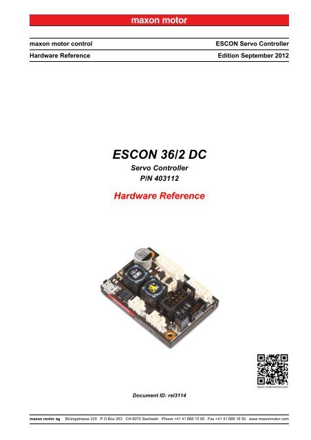
<strong>ESCON</strong> <strong>36</strong>/2 <strong>DC</strong><br />
Servo Controller<br />
P/N 403112<br />
<strong>Hardware</strong> <strong>Reference</strong><br />
Document ID: rel3114<br />
<strong>ESCON</strong> Servo Controller<br />
Edition September 2012<br />
maxon motor ag Brünigstrasse 220 P.O.Box 263 CH-6072 Sachseln Phone +41 41 666 15 00 Fax +41 41 666 16 50 www.maxonmotor.com
TABLE OF CONTENTS<br />
1 About 3<br />
1.1 About this Document . . . . . . . . . . . . . . . . . . . . . . . . . . . . . . . . . . . . . . . . . . . . 3<br />
1.2 About the Device . . . . . . . . . . . . . . . . . . . . . . . . . . . . . . . . . . . . . . . . . . . . . . . 4<br />
1.3 About the Safety Precautions. . . . . . . . . . . . . . . . . . . . . . . . . . . . . . . . . . . . . . 5<br />
2 Specifications 7<br />
2.1 Technical Data . . . . . . . . . . . . . . . . . . . . . . . . . . . . . . . . . . . . . . . . . . . . . . . . . 7<br />
2.2 Standards . . . . . . . . . . . . . . . . . . . . . . . . . . . . . . . . . . . . . . . . . . . . . . . . . . . . . 9<br />
3 <strong>Setup</strong> 11<br />
3.1 Generally applicable Rules. . . . . . . . . . . . . . . . . . . . . . . . . . . . . . . . . . . . . . . 11<br />
3.2 Determination of Power Supply . . . . . . . . . . . . . . . . . . . . . . . . . . . . . . . . . . . 12<br />
3.3 Cabling . . . . . . . . . . . . . . . . . . . . . . . . . . . . . . . . . . . . . . . . . . . . . . . . . . . . . . 13<br />
3.4 Connections . . . . . . . . . . . . . . . . . . . . . . . . . . . . . . . . . . . . . . . . . . . . . . . . . . 14<br />
3.5 Jumpers . . . . . . . . . . . . . . . . . . . . . . . . . . . . . . . . . . . . . . . . . . . . . . . . . . . . . 29<br />
3.6 Potentiometers . . . . . . . . . . . . . . . . . . . . . . . . . . . . . . . . . . . . . . . . . . . . . . . . 29<br />
3.7 Status Indicators. . . . . . . . . . . . . . . . . . . . . . . . . . . . . . . . . . . . . . . . . . . . . . . 30<br />
4 Wiring 31<br />
READ THIS FIRST<br />
These instructions are intended for qualified technical personnel. Prior commencing with any activities …<br />
• you must carefully read and understand this manual and<br />
• you must follow the instructions given therein.<br />
The <strong>ESCON</strong> <strong>36</strong>/2 <strong>DC</strong> is considered as partly completed machinery according to EU Directive 2006/42/EC, Article 2, Clause<br />
(g) and is intended to be incorporated into or assembled with other machinery or other partly completed machinery<br />
or equipment.<br />
Therefore, you must not put the device into service, …<br />
• unless you have made completely sure that the other machinery fully complies with the EU directive’s requirements!<br />
• unless the other machinery fulfills all relevant health and safety aspects!<br />
• unless all respective interfaces have been established and fulfill the herein stated requirements!<br />
A-2 Document ID: rel3114<br />
maxon motor control<br />
<strong>ESCON</strong> Servo Controller<br />
Edition: September 2012<br />
© 2012 maxon motor. Subject to change without prior notice.<br />
<strong>ESCON</strong> <strong>36</strong>/2 <strong>DC</strong> <strong>Hardware</strong> <strong>Reference</strong>
1 About<br />
1.1 About this Document<br />
About<br />
About this Document<br />
1.1.1 Intended Purpose<br />
The purpose of the present document is to familiarize you with the <strong>ESCON</strong> <strong>36</strong>/2 <strong>DC</strong> Servo Controller. It<br />
will highlight the tasks for safe and adequate installation and/or commissioning. Follow the described<br />
instructions …<br />
• to avoid dangerous situations,<br />
• to keep installation and/or commissioning time at a minimum,<br />
• to increase reliability and service life of the described equipment.<br />
The document contains performance data and specifications, information on fulfilled standards, details<br />
on connections and pin assignment, and wiring examples.<br />
1.1.2 Target Audience<br />
The present document is intended for trained and skilled personnel. It conveys information on how to<br />
understand and fulfill the respective work and duties.<br />
1.1.3 How to use<br />
Take note of the following notations and codes which will be used throughout the document.<br />
Notation Meaning<br />
(n) refers to an item (such as order number, list item, etc.)<br />
� denotes “see”, “see also”, “take note of” or “go to”<br />
Table 1-1 Notation used<br />
1.1.4 Symbols & Signs<br />
In the course of the present document, the following symbols and sings will be used.<br />
Type Symbol Meaning<br />
Safety Alert<br />
Prohibited<br />
Action<br />
Mandatory<br />
Action<br />
(typical)<br />
(typical)<br />
(typical)<br />
DANGER<br />
WARNING<br />
CAUTION<br />
Indicates an imminent hazardous situation. If not<br />
avoided, it will result in death or serious injury.<br />
Indicates a potential hazardous situation. If not<br />
avoided, it can result in death or serious injury.<br />
Indicates a probable hazardous situation or calls<br />
the attention to unsafe practices. If not avoided, it<br />
may result in injury.<br />
Indicates a dangerous action. Hence, you must not!<br />
Indicates a mandatory action. Hence, you must!<br />
maxon motor control<br />
<strong>ESCON</strong> Servo Controller Document ID: rel3114 1-3<br />
<strong>ESCON</strong> <strong>36</strong>/2 <strong>DC</strong> <strong>Hardware</strong> <strong>Reference</strong> Edition: September 2012<br />
© 2012 maxon motor. Subject to change without prior notice.
About<br />
About the Device<br />
Type Symbol Meaning<br />
Information<br />
Table 1-2 Symbols & Signs<br />
Requirement /<br />
Note / Remark<br />
Best Practice<br />
Material<br />
Damage<br />
1.1.5 Trademarks and Brand Names<br />
For easier legibility, registered brand names are listed below and will not be further tagged with their<br />
respective trademark. It must be understood that the brands (the list below is not necessarily concluding)<br />
are protected by copyright and/or other intellectual property rights even if their legal trademarks are<br />
omitted in the later course of this document.<br />
Brand Name Trademark Owner<br />
Table 1-3 Brand Names and Trademark Owners<br />
Indicates an activity you must perform prior<br />
continuing, or gives information on a particular item<br />
you need to observe.<br />
Indicates an advice or recommendation on the<br />
easiest and best way to further proceed.<br />
Windows® © Microsoft Corporation, USA-Redmond, WA<br />
Indicates information particular to possible damage<br />
of the equipment.<br />
1.1.6 Copyright<br />
© 2012 maxon motor. All rights reserved.<br />
The present document – including all parts thereof – is protected by copyright. Any use (including reproduction,<br />
translation, microfilming, and other means of electronic data processing) beyond the narrow<br />
restrictions of the copyright law without the prior approval of maxon motor ag, is not permitted and subject<br />
to prosecution under the applicable law.<br />
maxon motor ag<br />
Brünigstrasse 220<br />
P.O.Box 263<br />
CH-6072 Sachseln<br />
Phone<br />
Fax<br />
Web<br />
+41 (41) 666 15 00<br />
+41 (41) 666 16 50<br />
www.maxonmotor.com<br />
1.2 About the Device<br />
The <strong>ESCON</strong> <strong>36</strong>/2 <strong>DC</strong> is a small-sized, powerful 4-quadrant PWM servo controller for the highly efficient<br />
control of permanent magnet-activated <strong>DC</strong> motors up to approximately 72 Watts.<br />
The featured operating modes – speed control (closed loop), speed control (open loop), and current<br />
control – meet the highest requirements. The <strong>ESCON</strong> <strong>36</strong>/2 <strong>DC</strong> is designed being commanded by an<br />
analog set value and features extensive analog and digital I/O functionality.<br />
The device is designed to be configured via USB interface using the graphical user interface «<strong>ESCON</strong><br />
Studio» for Windows PCs.<br />
You can download the latest <strong>ESCON</strong> software version (as well as the latest edition of the documentation)<br />
from the internet under �http://escon.maxonmotor.com.<br />
1-4 Document ID: rel3114<br />
maxon motor control<br />
<strong>ESCON</strong> Servo Controller<br />
Edition: September 2012<br />
© 2012 maxon motor. Subject to change without prior notice.<br />
<strong>ESCON</strong> <strong>36</strong>/2 <strong>DC</strong> <strong>Hardware</strong> <strong>Reference</strong>
About<br />
About the Safety Precautions<br />
1.3 About the Safety Precautions<br />
• Make sure that you have read and understood the note “READ THIS FIRST” on page A-2!<br />
• Do not engage with any work unless you possess the stated skills (�chapter “1.1.2 Target<br />
Audience” on page 1-3)!<br />
• Refer to �chapter “1.1.4 Symbols & Signs” on page 1-3 to understand the subsequently used<br />
indicators!<br />
• You must observe any regulation applicable in the country and/or at the site of implementation<br />
with regard to health and safety/accident prevention and/or environmental protection!<br />
DANGER<br />
High Voltage and/or Electrical Shock<br />
Touching live wires causes death or serious injuries!<br />
• Consider any power cable as connected to life power, unless having proven the opposite!<br />
• Make sure that neither end of cable is connected to life power!<br />
• Make sure that power source cannot be engaged while work is in process!<br />
• Obey lock-out/tag-out procedures!<br />
• Make sure to securely lock any power engaging equipment against unintentional engagement and<br />
tag it with your name!<br />
Requirements<br />
• Make sure that all associated devices and components are installed according to local regulations.<br />
• Be aware that, by principle, an electronic apparatus can not be considered fail-safe. Therefore, you<br />
must make sure that any machine/apparatus has been fitted with independent monitoring and safety<br />
equipment. If the machine/apparatus should break down, if it is operated incorrectly, if the control unit<br />
breaks down or if the cables break or get disconnected, etc., the complete drive system must return –<br />
and be kept – in a safe operating mode.<br />
• Be aware that you are not entitled to perform any repair on components supplied by maxon motor.<br />
Electrostatic Sensitive Device (ESD)<br />
• Make sure to wear working cloth in compliance with ESD.<br />
• Handle device with extra care.<br />
maxon motor control<br />
<strong>ESCON</strong> Servo Controller Document ID: rel3114 1-5<br />
<strong>ESCON</strong> <strong>36</strong>/2 <strong>DC</strong> <strong>Hardware</strong> <strong>Reference</strong> Edition: September 2012<br />
© 2012 maxon motor. Subject to change without prior notice.
About<br />
About the Safety Precautions<br />
••page intentionally left blank••<br />
1-6 Document ID: rel3114<br />
maxon motor control<br />
<strong>ESCON</strong> Servo Controller<br />
Edition: September 2012<br />
© 2012 maxon motor. Subject to change without prior notice.<br />
<strong>ESCON</strong> <strong>36</strong>/2 <strong>DC</strong> <strong>Hardware</strong> <strong>Reference</strong>
2 Specifications<br />
2.1 Technical Data<br />
Electrical Rating<br />
Inputs & Outputs<br />
Voltage Outputs<br />
Nominal operating voltage V CC<br />
Absolute operating voltage<br />
V CC min / V CC max<br />
<strong>ESCON</strong> <strong>36</strong>/2 <strong>DC</strong> (403112)<br />
10…<strong>36</strong> V<strong>DC</strong><br />
8 V<strong>DC</strong> / 38 V<strong>DC</strong><br />
Output voltage (max.) 0.98 x V CC<br />
Output current I cont / I max (
Specifications<br />
Technical Data<br />
Environmental<br />
Conditions<br />
Temperature<br />
Table 2-4 Technical Data<br />
<strong>ESCON</strong> <strong>36</strong>/2 <strong>DC</strong> (403112)<br />
Figure 2-1 Dimensional Drawing [mm]<br />
Operation –30…+45°C<br />
Extended range *1)<br />
+45…+81°C<br />
Derating: –0.056 A/°C<br />
Storage –40…+85°C<br />
Humidity 20…80% (condensation not permitted)<br />
Remark: *1) Operation within the extended temperature range is permitted. However, a respective derating (declination of<br />
max. output current) as to the stated value will apply.<br />
2-8 Document ID: rel3114<br />
maxon motor control<br />
<strong>ESCON</strong> Servo Controller<br />
Edition: September 2012<br />
© 2012 maxon motor. Subject to change without prior notice.<br />
<strong>ESCON</strong> <strong>36</strong>/2 <strong>DC</strong> <strong>Hardware</strong> <strong>Reference</strong>
Specifications<br />
Standards<br />
2.2 Standards<br />
The described device has been successfully tested for compliance with the below listed standards. In<br />
practical terms, only the complete system (the fully operational equipment comprising all individual components,<br />
such as motor, servo controller, power supply unit, EMC filter, cabling etc.) can undergo an<br />
EMC test to ensure interference-free operation.<br />
Important Notice<br />
The device’s compliance with the mentioned standards does not imply its compliance within the final,<br />
ready to operate setup. In order to achieve compliance of your operational system, you must perform<br />
EMC testing of the involved equipment as a whole.<br />
Generic Standards<br />
Applied Standards<br />
Environmental<br />
Standards<br />
Table 2-5 Standards<br />
Electromagnetic Compatibility<br />
IEC/EN 61000-6-2 Immunity for industrial environments<br />
IEC/EN 61000-6-3<br />
IEC/EN 61000-6-3<br />
IEC/EN 55022<br />
(CISPR22)<br />
IEC/EN 61000-4-3<br />
Emission standard for residential, commercial and lightindustrial<br />
environments<br />
Radio disturbance characteristics / radio interference<br />
Radiated, radio-frequency, electromagnetic field immunity<br />
test >10 V/m<br />
IEC/EN 61000-4-4 Electrical fast transient/burst immunity test ±2 kV<br />
IEC/EN 61000-4-6<br />
Immunity to conducted disturbances, induced by radiofrequency<br />
fields 10 Vrms<br />
Others<br />
IEC/EN 60068-2-6 Environmental testing – Test Fc: Vibration (sinusoidal)<br />
MIL-STD-810F Random transport<br />
Safety Standards UL File Number E207844; unassembled printed circuit board<br />
maxon motor control<br />
<strong>ESCON</strong> Servo Controller Document ID: rel3114 2-9<br />
<strong>ESCON</strong> <strong>36</strong>/2 <strong>DC</strong> <strong>Hardware</strong> <strong>Reference</strong> Edition: September 2012<br />
© 2012 maxon motor. Subject to change without prior notice.
Specifications<br />
Standards<br />
••page intentionally left blank••<br />
2-10 Document ID: rel3114<br />
maxon motor control<br />
<strong>ESCON</strong> Servo Controller<br />
Edition: September 2012<br />
© 2012 maxon motor. Subject to change without prior notice.<br />
<strong>ESCON</strong> <strong>36</strong>/2 <strong>DC</strong> <strong>Hardware</strong> <strong>Reference</strong>
3 <strong>Setup</strong><br />
<strong>Setup</strong><br />
Generally applicable Rules<br />
IMPORTANT NOTICE: PREREQUISITES FOR PERMISSION TO COMMENCE INSTALLATION<br />
The <strong>ESCON</strong> <strong>36</strong>/2 <strong>DC</strong> is considered as partly completed machinery according to EU Directive 2006/42/<br />
EC, Article 2, Clause (g) and is intended to be incorporated into or assembled with other machinery<br />
or other partly completed machinery or equipment.<br />
WARNING<br />
Risk of Injury<br />
Operating the device without the full compliance of the surrounding system with the EU Directive<br />
2006/42/EC may cause serious injuries!<br />
• Do not operate the device, unless you have made completely sure that the other machinery fully<br />
complies with the EU directive’s requirements!<br />
• Do not operate the device, unless the other machinery fulfills all relevant health and safety<br />
aspects!<br />
• Do not operate the device, unless all respective interfaces have been established and fulfill the<br />
requirements stated in this document!<br />
3.1 Generally applicable Rules<br />
For each possible motor variant you will find information on the from/to connections and the cables you<br />
will require. If you should decide not to use the ready-made maxon cables, you must establish the<br />
respective connections as to �chapter “3.4.7 <strong>ESCON</strong> <strong>36</strong>/2 <strong>DC</strong> Connector Set” on page 3-28 and<br />
�chapter “4 Wiring” on page 4-31.<br />
Maximal permitted Supply Voltage<br />
• Make sure that supply power is between 10…<strong>36</strong> V<strong>DC</strong>.<br />
• Supply voltages above 38 V<strong>DC</strong>, or wrong polarity will destroy the unit.<br />
• Note that the necessary output current is depending on the load torque. Yet, the output current limits<br />
of the <strong>ESCON</strong> <strong>36</strong>/2 <strong>DC</strong> are as follows; continuous max. 2 A / short-time (acceleration) max. 4 A.<br />
How to read the Wiring Details<br />
The subsequent description follows this scheme:<br />
• Column “J… & Head A”: Pin number…<br />
– of the socket,<br />
– of the corresponding plug, and<br />
– of Head A of the matching prefab maxon cable.<br />
• Column “Prefab Cable”: Wire color of the prefab maxon cable.<br />
• Column “Head B”: Pin number of Head B of the matching prefab maxon cable.<br />
maxon motor control<br />
<strong>ESCON</strong> Servo Controller Document ID: rel3114 3-11<br />
<strong>ESCON</strong> <strong>36</strong>/2 <strong>DC</strong> <strong>Hardware</strong> <strong>Reference</strong> Edition: September 2012<br />
© 2012 maxon motor. Subject to change without prior notice.
<strong>Setup</strong><br />
Determination of Power Supply<br />
3.2 Determination of Power Supply<br />
Basically, any power supply may be used, provided it meets the minimal requirements stated below.<br />
Power Supply Requirements<br />
Output voltage V 10…<strong>36</strong> V<strong>DC</strong><br />
CC<br />
Absolute output voltage min. 8 V<strong>DC</strong>; max. 38 V<strong>DC</strong><br />
Output current<br />
Depending on load<br />
(continuous max. 2 A; short-time (acceleration) max. 4 A (
<strong>Setup</strong><br />
Cabling<br />
3.3 Cabling<br />
Here you can get the connection information required to commission your <strong>ESCON</strong> <strong>36</strong>/2 <strong>DC</strong>. You will find<br />
all details for both approaches, Plug&Play and making your own cables.<br />
PLUG&PLAY<br />
Take advantage of maxon’s prefab cable assemblies. They come as ready-to-use parts and will help<br />
you to reduce commissioning time to a minimum.<br />
a) Check the «Cable Selector» (�Table 3-6) to find the cable assemblies’ order number<br />
matching the setup you will be using.<br />
b) Follow the cross-reference to get the cable assemblies’ pin assignment.<br />
MAKE&BAKE YOUR OWN<br />
a) Check the «Cable Selector» (�Table 3-6) to find the required cables for the setup you will<br />
be using.<br />
b) Follow the cross-reference to get the cable’s specification and pin assignment.<br />
c) Utilize the installation kit (�page 3-28) containing plugs and terminals that will fit the controller’s<br />
sockets.<br />
Designation<br />
Table 3-6 Cable Selector<br />
Cable<br />
Order<br />
number<br />
maxon motor control<br />
<strong>ESCON</strong> Servo Controller Document ID: rel3114 3-13<br />
<strong>ESCON</strong> <strong>36</strong>/2 <strong>DC</strong> <strong>Hardware</strong> <strong>Reference</strong> Edition: September 2012<br />
© 2012 maxon motor. Subject to change without prior notice.<br />
�<br />
page<br />
Socket<br />
Separated<br />
Motor/Encoder<br />
Cable<br />
<strong>DC</strong> Motor<br />
with…<br />
Integrated<br />
Motor/Encoder<br />
Ribbon Cable<br />
<strong>ESCON</strong> Power Cable 403957 3-14 J1 X X<br />
<strong>ESCON</strong> <strong>DC</strong> Motor Cable 403962 3-15 J2 X<br />
<strong>ESCON</strong> Encoder Cable 275934 3-18 J4 O O<br />
<strong>ESCON</strong> Analog I/O Cable 403964 3-25 J6 O O<br />
<strong>ESCON</strong> Digital I/O Cable 403965 3-22 J5 X X<br />
USB 2.0 Type A-micro B Cable 403968 3-27 J7 X X<br />
Legend: X = required / O = optional
<strong>Setup</strong><br />
Connections<br />
3.4 Connections<br />
The actual connection will depend on the overall configuration of your drive system and the type of<br />
motor you will be using. Some connections must be established in a given way, while for motor (J2/J2A<br />
and encoder (J4/J4A) alternative plug-in locations can be chosen from.<br />
Follow the description in given order and choose the connection scheme that suits the respective components<br />
you are using. For corresponding wiring diagrams �chapter “4 Wiring” on page 4-31.<br />
3.4.1 Power (J1)<br />
Figure 3-2 Power Socket J1<br />
J1 &<br />
Head A<br />
Prefab<br />
Cable<br />
Head B<br />
Pin Color Pin<br />
Table 3-7 Power Socket J1 – Pin Assignment & Cabling<br />
Table 3-8 <strong>ESCON</strong> Power Cable<br />
Signal Description<br />
1 white – Power_GND Ground of supply voltage<br />
2 brown + V CC Power supply voltage (+10…+<strong>36</strong> V<strong>DC</strong>)<br />
Cable cross-section 2 x 0.34 mm 2<br />
Length 1.5 m<br />
Head A<br />
<strong>ESCON</strong> Power Cable (403957)<br />
Suitable plugs<br />
Suitable contacts<br />
Head B Cable end sleeves 0.34 mm 2<br />
Hirose DF3-2S-2C<br />
Hirose DF3-22SC…<br />
3-14 Document ID: rel3114<br />
maxon motor control<br />
<strong>ESCON</strong> Servo Controller<br />
Edition: September 2012<br />
© 2012 maxon motor. Subject to change without prior notice.<br />
<strong>ESCON</strong> <strong>36</strong>/2 <strong>DC</strong> <strong>Hardware</strong> <strong>Reference</strong>
3.4.2 Motor (J2 / J2A)<br />
Potential Destruction<br />
Use only one of the two sockets – either J2 or J2A!<br />
SOCKET J2<br />
Figure 3-3 Motor Socket J2<br />
J2 &<br />
Head A<br />
Prefab<br />
Cable<br />
Head B<br />
Pin Color Pin<br />
Table 3-9 Motor Socket J2 – Pin Assignment & Cabling<br />
Table 3-10 <strong>ESCON</strong> <strong>DC</strong> Motor Cable<br />
Signal Description<br />
1 white Motor (+M) Motor +<br />
2 brown Motor (–M) Motor –<br />
3 black Motor shield Cable shield<br />
<strong>ESCON</strong> <strong>DC</strong> Motor Cable (403962)<br />
Cable cross-section 2 x 0.34 mm 2 shielded<br />
Length 1.5 m<br />
Head A<br />
Suitable plugs<br />
Suitable contacts<br />
Head B Cable end sleeves 0.34 mm 2<br />
Hirose DF3-3S-2C<br />
Hirose DF3-22SC…<br />
<strong>Setup</strong><br />
Connections<br />
maxon motor control<br />
<strong>ESCON</strong> Servo Controller Document ID: rel3114 3-15<br />
<strong>ESCON</strong> <strong>36</strong>/2 <strong>DC</strong> <strong>Hardware</strong> <strong>Reference</strong> Edition: September 2012<br />
© 2012 maxon motor. Subject to change without prior notice.
<strong>Setup</strong><br />
Connections<br />
SOCKET J2A<br />
Figure 3-4 Motor Socket J2A<br />
J2A &<br />
Head A<br />
Prefab<br />
Cable<br />
Head B<br />
Pin Color Pin<br />
Table 3-11 Motor Socket J2A – Pin Assignment<br />
Signal Description<br />
1 Motor (+M) Motor +<br />
2 Motor (–M) Motor –<br />
Specification / Accessories<br />
Type 2 poles, spring-loaded contacts, pitch 2.5 mm<br />
Suitable cables<br />
Rigid 0.14…0.5 mm 2 / wire stripping length 6 mm<br />
Flexible<br />
Suitable tools Miniature screwdriver, size “00”<br />
Table 3-12 Motor Socket J2A – Specification & Accessories<br />
0.2…0.5 mm 2 / wire stripping length 6 mm<br />
0.25…0.5 mm 2 / wire stripping length 6 mm, cable end sleeves<br />
3-16 Document ID: rel3114<br />
maxon motor control<br />
<strong>ESCON</strong> Servo Controller<br />
Edition: September 2012<br />
© 2012 maxon motor. Subject to change without prior notice.<br />
<strong>ESCON</strong> <strong>36</strong>/2 <strong>DC</strong> <strong>Hardware</strong> <strong>Reference</strong>
3.4.3 Encoder (J4 / J4A)<br />
Potential Destruction<br />
Use only one of the two sockets – either J4 or J4A!<br />
SOCKET J4<br />
Figure 3-5 Encoder Socket J4<br />
J4 &<br />
Head A<br />
Prefab<br />
Cable<br />
Head B<br />
Pin Color Pin<br />
Table 3-13 Encoder Socket J4 – Pin Assignment & Cabling<br />
<strong>Setup</strong><br />
Connections<br />
Note<br />
If you are using a maxon <strong>DC</strong> motor with integrated Motor/Encoder Ribbon Cable, make sure to<br />
close both JP1 jumpers (�chapter “3.5 Jumpers” on page 3-29).<br />
Table 3-14 Encoder Socket J4 – Accessories<br />
Signal Description<br />
1 Motor (+M) Motor +M (�note below)<br />
2 +5 V<strong>DC</strong> Encoder supply voltage (+5 V<strong>DC</strong>; ≤70 mA)<br />
3 GND Ground<br />
4 Motor (–M) Motor –M (�note below)<br />
5 Channel A\ Channel A complement<br />
6 Channel A Channel A<br />
7 Channel B\ Channel B complement<br />
8 Channel B Channel B<br />
9 not connected –<br />
10 not connected –<br />
Suitable strain<br />
relief<br />
Accessories<br />
Lock 2 levers, Harting (09 18 000 9905)<br />
Retainer<br />
For sockets with strain relief:<br />
1 retainer clip, height 13.5 mm, 3M (3505-8110)<br />
For sockets without strain relief:<br />
1 retainer clip, height 7.9 mm, 3M (3505-8010)<br />
Latch For sockets with strain relief: 2 pieces, 3M (3505-33B)<br />
maxon motor control<br />
<strong>ESCON</strong> Servo Controller Document ID: rel3114 3-17<br />
<strong>ESCON</strong> <strong>36</strong>/2 <strong>DC</strong> <strong>Hardware</strong> <strong>Reference</strong> Edition: September 2012<br />
© 2012 maxon motor. Subject to change without prior notice.
<strong>Setup</strong><br />
Connections<br />
Table 3-15 <strong>ESCON</strong> Encoder Cable<br />
<strong>ESCON</strong> Encoder Cable (275934)<br />
Cable cross-section 10 x AWG28, round-jacket, twisted pair flat cable, pitch 1.27 mm<br />
Length 3.20 m<br />
Head A DIN 41651 female, pitch 2.54 mm, 10 poles, with strain relief<br />
Head B DIN 41651 Plug, pitch 2.54 mm, 10 poles, with strain relief<br />
3-18 Document ID: rel3114<br />
maxon motor control<br />
<strong>ESCON</strong> Servo Controller<br />
Edition: September 2012<br />
© 2012 maxon motor. Subject to change without prior notice.<br />
<strong>ESCON</strong> <strong>36</strong>/2 <strong>DC</strong> <strong>Hardware</strong> <strong>Reference</strong>
SOCKET J4A<br />
Figure 3-6 Encoder Socket J4A<br />
J4A &<br />
Head A<br />
Prefab<br />
Cable<br />
Head B<br />
Pin Color Pin<br />
1 not connected –<br />
Table 3-16 Encoder Socket J4A – Pin Assignment<br />
Signal Description<br />
Table 3-17 Encoder Socket J4A – Specification & Accessories<br />
<strong>Setup</strong><br />
Connections<br />
2 +5 V<strong>DC</strong> Encoder supply voltage (+5 V<strong>DC</strong>; ≤70 mA)<br />
3 GND Ground<br />
4 not connected –<br />
5 Channel A\ Channel A complement<br />
6 Channel A Channel A<br />
7 Channel B\ Channel B complement<br />
8 Channel B Channel B<br />
9 not connected –<br />
10 not connected –<br />
Specification / Accessories<br />
Type 2 x 5 poles, half pitch box header, pitch 1.27/1.27 mm<br />
Suitable plugs<br />
Samtec: FFSD series<br />
W+P Products: 376 series<br />
Elcotron: I<strong>DC</strong>32 series<br />
Suitable cables Flat ribbon cable AWG 30<br />
maxon motor control<br />
<strong>ESCON</strong> Servo Controller Document ID: rel3114 3-19<br />
<strong>ESCON</strong> <strong>36</strong>/2 <strong>DC</strong> <strong>Hardware</strong> <strong>Reference</strong> Edition: September 2012<br />
© 2012 maxon motor. Subject to change without prior notice.
<strong>Setup</strong><br />
Connections<br />
Best Practice<br />
• Because of its resistance against electrical interferences, we recommend using differential<br />
scheme. Nevertheless, the controller supports both schemes – differential and single-ended.<br />
• The controller does not require an index impulse (Ch I, Ch I\).<br />
• For best performance, we strongly recommend using encoders with line driver. Otherwise,<br />
speed limitations may apply due to slow switching edges.<br />
Differential<br />
Min. differential input voltage ±200 mV<br />
Max. input voltage +12 V<strong>DC</strong> / –12 V<strong>DC</strong><br />
Line receiver (internal) EIA RS422 Standard<br />
Max. input frequency 1 MHz<br />
Figure 3-7 Encoder Input Circuit Ch A “Differential” (analogously valid also for Ch B)<br />
3-20 Document ID: rel3114<br />
maxon motor control<br />
<strong>ESCON</strong> Servo Controller<br />
Edition: September 2012<br />
© 2012 maxon motor. Subject to change without prior notice.<br />
<strong>ESCON</strong> <strong>36</strong>/2 <strong>DC</strong> <strong>Hardware</strong> <strong>Reference</strong>
Input voltage<br />
Single-ended<br />
0…5 V<strong>DC</strong><br />
Max. input voltage +12 V<strong>DC</strong> / –12 V<strong>DC</strong><br />
Logic 0 2.4 V<br />
Input high current I = typically –50 μA @ 5 V<br />
IH<br />
Input low current I IL = typically –550 μA @ 0 V<br />
Max. input frequency 100 kHz<br />
Figure 3-8 Encoder Input Circuit Ch A “Single-ended” (analogously valid also for Ch B)<br />
<strong>Setup</strong><br />
Connections<br />
maxon motor control<br />
<strong>ESCON</strong> Servo Controller Document ID: rel3114 3-21<br />
<strong>ESCON</strong> <strong>36</strong>/2 <strong>DC</strong> <strong>Hardware</strong> <strong>Reference</strong> Edition: September 2012<br />
© 2012 maxon motor. Subject to change without prior notice.
<strong>Setup</strong><br />
Connections<br />
3.4.4 Digital I/Os (J5)<br />
Figure 3-9 Digital I/Os Socket J5<br />
J5 &<br />
Head A<br />
Prefab<br />
Cable<br />
Head B<br />
Pin Color Pin<br />
Table 3-18 Digital I/Os Socket J5 – Pin Assignment & Cabling<br />
Table 3-19 <strong>ESCON</strong> Digital I/O Cable<br />
Signal Description<br />
1 white DigIN1 Digital input 1<br />
2 brown DigIN2 Digital input 2<br />
3 green DigIN/DigOUT3 Digital input/output 3<br />
4 yellow DigIN/DigOUT4 Digital input/output 4<br />
5 grey GND Signal ground<br />
6 pink +5 V<strong>DC</strong> Auxiliary output voltage (+5 V<strong>DC</strong>; ≤10 mA)<br />
Cable cross-section 6 x 0.14 mm 2<br />
Length 1.5 m<br />
Head A<br />
<strong>ESCON</strong> Digital I/O Cable (403965)<br />
Suitable plugs<br />
Suitable contacts<br />
Head B Cable end sleeves 0.14 mm 2<br />
Hirose DF3-6S-2C<br />
Hirose DF3-2428SC…<br />
3-22 Document ID: rel3114<br />
maxon motor control<br />
<strong>ESCON</strong> Servo Controller<br />
Edition: September 2012<br />
© 2012 maxon motor. Subject to change without prior notice.<br />
<strong>ESCON</strong> <strong>36</strong>/2 <strong>DC</strong> <strong>Hardware</strong> <strong>Reference</strong>
3.4.4.1 Digital Input 1<br />
Input voltage 0…<strong>36</strong> V<strong>DC</strong><br />
Max. input voltage +<strong>36</strong> V<strong>DC</strong> / –<strong>36</strong> V<strong>DC</strong><br />
Logic 0 typically 2.4 V<br />
Input resistance<br />
Figure 3-10 DigIN1 Circuit<br />
3.4.4.2 Digital Input 2<br />
Figure 3-11 DigIN2 Circuit<br />
typically 47 kΩ (
<strong>Setup</strong><br />
Connections<br />
3.4.4.3 Digital Inputs/Outputs 3 and 4<br />
Figure 3-12 DigIN3 Circuit (analogously valid also for DigIN4)<br />
Figure 3-13 DigOUT3 Circuit (analogously valid also for DigOUT4)<br />
3-24 Document ID: rel3114<br />
maxon motor control<br />
<strong>ESCON</strong> Servo Controller<br />
Edition: September 2012<br />
© 2012 maxon motor. Subject to change without prior notice.<br />
<strong>ESCON</strong> <strong>36</strong>/2 <strong>DC</strong> <strong>Hardware</strong> <strong>Reference</strong><br />
DigIN<br />
Input voltage 0…<strong>36</strong> V<strong>DC</strong><br />
Max. input voltage +<strong>36</strong> V<strong>DC</strong><br />
Logic 0 typically 2.4 V<br />
Input resistance<br />
typically 47 kΩ (
3.4.5 Analog I/Os (J6)<br />
Figure 3-14 Analog I/Os Socket J6<br />
J6 &<br />
Head A<br />
Prefab<br />
Cable<br />
Head B<br />
Pin Color Pin<br />
Table 3-20 Analog I/Os Socket J6 – Pin Assignment & Cabling<br />
Table 3-21 <strong>ESCON</strong> Analog I/O Cable<br />
Signal Description<br />
1 white AnIN1+ Analog input 1, positive signal<br />
2 brown AnIN1– Analog input 1, negative signal<br />
3 green AnIN2+ Analog input 2, positive signal<br />
4 yellow AnIN2– Analog input 2, negative signal<br />
5 grey AnOUT1 Analog output 1<br />
6 pink AnOUT2 Analog output 2<br />
7 blue GND Signal ground<br />
Cable cross-section 7 x 0.14 mm 2<br />
Length 1.5 m<br />
Head A<br />
<strong>ESCON</strong> Analog I/O Cable (403964)<br />
Suitable plugs<br />
Suitable contacts<br />
Head B Cable end sleeves 0.14 mm 2<br />
Hirose DF3-7S-2C<br />
Hirose DF3-2428SC…<br />
<strong>Setup</strong><br />
Connections<br />
maxon motor control<br />
<strong>ESCON</strong> Servo Controller Document ID: rel3114 3-25<br />
<strong>ESCON</strong> <strong>36</strong>/2 <strong>DC</strong> <strong>Hardware</strong> <strong>Reference</strong> Edition: September 2012<br />
© 2012 maxon motor. Subject to change without prior notice.
<strong>Setup</strong><br />
Connections<br />
3.4.5.1 Analog Inputs 1 and 2<br />
Input voltage –10…+10 V<strong>DC</strong> (differential)<br />
Max. input voltage +24 V<strong>DC</strong> / –24 V<strong>DC</strong><br />
Common mode voltage –5…+10 V<strong>DC</strong> (referenced to GND)<br />
Input resistance<br />
A/D converter 12-bit<br />
Resolution 5.07 mV<br />
Bandwidth 10 kHz<br />
Figure 3-15 AnIN1 Circuit (analogously valid also for AnIN2)<br />
3.4.5.2 Analog Outputs 1 and 2<br />
Output voltage –4…+4 V<strong>DC</strong><br />
D/A converter 12-bit<br />
Resolution 2.30 mV<br />
100 kΩ (differential)<br />
50 kΩ (referenced to GND)<br />
Refresh rate<br />
AnOUT1: 26.8 kHz<br />
AnOUT2: 5.4 kHz<br />
Analog bandwidth of output amplifier 20 kHz<br />
Max. capacitive load 10 nF<br />
Max. output current 1 mA<br />
Figure 3-16 AnOUT1 Circuit (analogously valid also for AnOUT2)<br />
3-26 Document ID: rel3114<br />
maxon motor control<br />
<strong>ESCON</strong> Servo Controller<br />
Edition: September 2012<br />
© 2012 maxon motor. Subject to change without prior notice.<br />
<strong>ESCON</strong> <strong>36</strong>/2 <strong>DC</strong> <strong>Hardware</strong> <strong>Reference</strong>
3.4.6 USB (J7)<br />
Figure 3-17 USB Socket J7<br />
Note<br />
Column “Head B” (�Table 3-22) refers to USB terminals of your PC.<br />
J7 &<br />
Head A<br />
Prefab<br />
Cable<br />
Head B<br />
Pin Color Pin<br />
Table 3-22 USB Socket J7 – Pin Assignment & Cabling<br />
Table 3-23 USB 2.0 Type A-micro B Cable<br />
Signal Description<br />
1 1 V BUS USB BUS supply voltage input +5 V<strong>DC</strong><br />
2 2 D– USB Data– (twisted pair with Data+)<br />
3 3 D+ USB Data+ (twisted pair with Data–)<br />
4 – ID not connected<br />
5 4 GND USB ground<br />
USB 2.0 Type A-micro B Cable (403968)<br />
Cable cross-section According to USB 2.0 specification<br />
Length 1.5 m<br />
Head A USB Type “micro B”, male<br />
Head B USB Type “A”, male<br />
USB Standard 2.0 (Full Speed)<br />
Max. bit rate 12 Mbit/s<br />
Max. bus supply voltage +5.25 V<strong>DC</strong><br />
Typical input current 60 mA<br />
Max. <strong>DC</strong> data input voltage –0.5…+3.8 V<strong>DC</strong><br />
<strong>Setup</strong><br />
Connections<br />
maxon motor control<br />
<strong>ESCON</strong> Servo Controller Document ID: rel3114 3-27<br />
<strong>ESCON</strong> <strong>36</strong>/2 <strong>DC</strong> <strong>Hardware</strong> <strong>Reference</strong> Edition: September 2012<br />
© 2012 maxon motor. Subject to change without prior notice.
<strong>Setup</strong><br />
Connections<br />
3.4.7 <strong>ESCON</strong> <strong>36</strong>/2 <strong>DC</strong> Connector Set<br />
If you decide not to employ maxon motor’s prefab cable assemblies, you might wish to use the prepackaged<br />
kit that contains all connectors required to make up your own cabling.<br />
<strong>ESCON</strong> <strong>36</strong>/2 <strong>DC</strong> Connector Set» (404404)<br />
For Socket Specification Quantity<br />
J1 Hirose crimping socket, 2 poles (DF3-2S-2C) 1<br />
J1, J2 Hirose crimping contact for Socket (DF3-22SC…) 6<br />
J2 Hirose crimping socket, 3 poles (DF3-3S-2C) 1<br />
J4 3M Retainer Clip with Strain Relief, H=13.5 mm (3505-8110) 1<br />
J5 Hirose crimping socket, 6 poles (DF3-6S-2C) 1<br />
J5, J6 Hirose crimping contact for Socket (DF3-2428SC…) 14<br />
J6 Hirose crimping socket, 7 poles (DF3-7S-2C) 1<br />
Table 3-24 <strong>ESCON</strong> <strong>36</strong>/2 <strong>DC</strong> Connector Set – Content<br />
Best Practice<br />
If you should decide not to use the ready-made cable assemblies, we strongly suggest that you use the<br />
following hand tools:<br />
• Hirose hand crimper (DF3-TA22HC) for crimping contacts DF3-22SC…<br />
• Hirose hand crimper (DF3-TA2428HC) for crimping contacts DF3-2428SC…<br />
3-28 Document ID: rel3114<br />
maxon motor control<br />
<strong>ESCON</strong> Servo Controller<br />
Edition: September 2012<br />
© 2012 maxon motor. Subject to change without prior notice.<br />
<strong>ESCON</strong> <strong>36</strong>/2 <strong>DC</strong> <strong>Hardware</strong> <strong>Reference</strong>
3.5 Jumpers<br />
3.6 Potentiometers<br />
STOP<br />
Check on safety precautions before continuing (�page 1-5).<br />
<strong>Setup</strong><br />
Jumpers<br />
JUMPER JP1<br />
For maxon <strong>DC</strong> motor with integrated Motor/Encoder Ribbon Cable, activate the motor terminal by setting<br />
both jumpers to CLOSED (�Figure 3-20, right).<br />
Figure 3-18 Jumper JP1<br />
Figure 3-19 Jumper JP1 – Location<br />
Figure 3-20 Jumper JP1 – OPEN, Default Setting (left) / CLOSED (right)<br />
POTENTIOMETER P1<br />
Adjustment angle 210°<br />
Type Linear<br />
Figure 3-21 Potentiometer P1 – Location & Adjustment Range<br />
maxon motor control<br />
<strong>ESCON</strong> Servo Controller Document ID: rel3114 3-29<br />
<strong>ESCON</strong> <strong>36</strong>/2 <strong>DC</strong> <strong>Hardware</strong> <strong>Reference</strong> Edition: September 2012<br />
© 2012 maxon motor. Subject to change without prior notice.
<strong>Setup</strong><br />
Status Indicators<br />
3.7 Status Indicators<br />
Light-emitting diodes (LEDs) indicate the actual operating status (green) and possible errors (red).<br />
Figure 3-22 LEDs – Location<br />
Green<br />
LED<br />
Red<br />
Status / Error<br />
off off INIT<br />
slow off DISABLE<br />
on off ENABLE<br />
2x off STOPPING; STOP STANDSTILL<br />
off 1x ERROR<br />
off 2x ERROR<br />
Table 3-25 LEDs – Interpretation of Condition<br />
• Vcc Overvoltage Error<br />
• Vcc Undervoltage Error<br />
• +5 V<strong>DC</strong> Undervoltage Error<br />
• Thermal Overload Error<br />
• Overcurrent Error<br />
• Power Stage Protection Error<br />
off 3x ERROR<br />
• Encoder Cable Break Error<br />
• Encoder Polarity Error<br />
• <strong>DC</strong> Tacho Cable Break Error<br />
• <strong>DC</strong> Tacho Polarity Error<br />
off 4x ERROR • PWM Set Value Input out of Range Error<br />
off on ERROR<br />
• Auto Tuning Identification Error<br />
• Internal Software Error<br />
3-30 Document ID: rel3114<br />
maxon motor control<br />
<strong>ESCON</strong> Servo Controller<br />
Edition: September 2012<br />
© 2012 maxon motor. Subject to change without prior notice.<br />
<strong>ESCON</strong> <strong>36</strong>/2 <strong>DC</strong> <strong>Hardware</strong> <strong>Reference</strong>
4 Wiring<br />
Figure 4-23 Interfaces – Designations and Location<br />
Remark<br />
The subsequent diagrams feature these signs:<br />
• PCB mounting hole<br />
• Ground safety earth connection (optional)<br />
Wiring<br />
maxon motor control<br />
<strong>ESCON</strong> Servo Controller Document ID: rel3114 4-31<br />
<strong>ESCON</strong> <strong>36</strong>/2 <strong>DC</strong> <strong>Hardware</strong> <strong>Reference</strong> Edition: September 2012<br />
© 2012 maxon motor. Subject to change without prior notice.
Wiring<br />
4.1 maxon <strong>DC</strong> motor<br />
SOCKET J2<br />
Figure 4-24 maxon <strong>DC</strong> motor (J2)<br />
4-32 Document ID: rel3114<br />
maxon motor control<br />
<strong>ESCON</strong> Servo Controller<br />
Edition: September 2012<br />
© 2012 maxon motor. Subject to change without prior notice.<br />
<strong>ESCON</strong> <strong>36</strong>/2 <strong>DC</strong> <strong>Hardware</strong> <strong>Reference</strong>
4.2 maxon <strong>DC</strong> motor with <strong>DC</strong> Tacho<br />
SOCKET J2<br />
Figure 4-25 maxon <strong>DC</strong> motor with <strong>DC</strong> Tacho (J2)<br />
Wiring<br />
maxon motor control<br />
<strong>ESCON</strong> Servo Controller Document ID: rel3114 4-33<br />
<strong>ESCON</strong> <strong>36</strong>/2 <strong>DC</strong> <strong>Hardware</strong> <strong>Reference</strong> Edition: September 2012<br />
© 2012 maxon motor. Subject to change without prior notice.
Wiring<br />
4.3 maxon <strong>DC</strong> motor with separated Motor/Encoder Cable<br />
SOCKETS J2 / J4<br />
Figure 4-26 maxon <strong>DC</strong> motor with Encoder – separate Cables (J2 / J4)<br />
4-34 Document ID: rel3114<br />
maxon motor control<br />
<strong>ESCON</strong> Servo Controller<br />
Edition: September 2012<br />
© 2012 maxon motor. Subject to change without prior notice.<br />
<strong>ESCON</strong> <strong>36</strong>/2 <strong>DC</strong> <strong>Hardware</strong> <strong>Reference</strong>
SOCKETS J2 / J4A<br />
Figure 4-27 maxon <strong>DC</strong> motor with Encoder – separate Cables (J2 / J4A)<br />
Wiring<br />
maxon motor control<br />
<strong>ESCON</strong> Servo Controller Document ID: rel3114 4-35<br />
<strong>ESCON</strong> <strong>36</strong>/2 <strong>DC</strong> <strong>Hardware</strong> <strong>Reference</strong> Edition: September 2012<br />
© 2012 maxon motor. Subject to change without prior notice.
Wiring<br />
SOCKETS J2A / J4<br />
Figure 4-28 maxon <strong>DC</strong> motor with Encoder – separate Cables (J2A / J4)<br />
4-<strong>36</strong> Document ID: rel3114<br />
maxon motor control<br />
<strong>ESCON</strong> Servo Controller<br />
Edition: September 2012<br />
© 2012 maxon motor. Subject to change without prior notice.<br />
<strong>ESCON</strong> <strong>36</strong>/2 <strong>DC</strong> <strong>Hardware</strong> <strong>Reference</strong>
SOCKETS J2A / J4A<br />
Figure 4-29 maxon <strong>DC</strong> motor with Encoder – separate Cables (J2A / J4A)<br />
Wiring<br />
maxon motor control<br />
<strong>ESCON</strong> Servo Controller Document ID: rel3114 4-37<br />
<strong>ESCON</strong> <strong>36</strong>/2 <strong>DC</strong> <strong>Hardware</strong> <strong>Reference</strong> Edition: September 2012<br />
© 2012 maxon motor. Subject to change without prior notice.
Wiring<br />
4.4 maxon <strong>DC</strong> motor with integrated Motor/Encoder Ribbon Cable<br />
SOCKET J4<br />
Figure 4-30 maxon <strong>DC</strong> motor with Encoder – integrated Ribbon Cable (J4)<br />
Note<br />
For jumper settings �chapter “ Jumper JP1” on page 3-29.<br />
4-38 Document ID: rel3114<br />
maxon motor control<br />
<strong>ESCON</strong> Servo Controller<br />
Edition: September 2012<br />
© 2012 maxon motor. Subject to change without prior notice.<br />
<strong>ESCON</strong> <strong>36</strong>/2 <strong>DC</strong> <strong>Hardware</strong> <strong>Reference</strong>
LIST OF FIGURES<br />
Figure 2-1 Dimensional Drawing [mm]. . . . . . . . . . . . . . . . . . . . . . . . . . . . . . . . . . . . . . . . . . . . . . .8<br />
Figure 3-2 Power Socket J1. . . . . . . . . . . . . . . . . . . . . . . . . . . . . . . . . . . . . . . . . . . . . . . . . . . . . .14<br />
Figure 3-3 Motor Socket J2 . . . . . . . . . . . . . . . . . . . . . . . . . . . . . . . . . . . . . . . . . . . . . . . . . . . . . .15<br />
Figure 3-4 Motor Socket J2A . . . . . . . . . . . . . . . . . . . . . . . . . . . . . . . . . . . . . . . . . . . . . . . . . . . . .16<br />
Figure 3-5 Encoder Socket J4 . . . . . . . . . . . . . . . . . . . . . . . . . . . . . . . . . . . . . . . . . . . . . . . . . . . .17<br />
Figure 3-6 Encoder Socket J4A . . . . . . . . . . . . . . . . . . . . . . . . . . . . . . . . . . . . . . . . . . . . . . . . . . .19<br />
Figure 3-7 Encoder Input Circuit Ch A “Differential” (analogously valid also for Ch B) . . . . . . . . .20<br />
Figure 3-8 Encoder Input Circuit Ch A “Single-ended” (analogously valid also for Ch B) . . . . . . .21<br />
Figure 3-9 Digital I/Os Socket J5 . . . . . . . . . . . . . . . . . . . . . . . . . . . . . . . . . . . . . . . . . . . . . . . . . .22<br />
Figure 3-10 DigIN1 Circuit . . . . . . . . . . . . . . . . . . . . . . . . . . . . . . . . . . . . . . . . . . . . . . . . . . . . . . . .23<br />
Figure 3-11 DigIN2 Circuit . . . . . . . . . . . . . . . . . . . . . . . . . . . . . . . . . . . . . . . . . . . . . . . . . . . . . . . .23<br />
Figure 3-12 DigIN3 Circuit (analogously valid also for DigIN4) . . . . . . . . . . . . . . . . . . . . . . . . . . . .24<br />
Figure 3-13 DigOUT3 Circuit (analogously valid also for DigOUT4) . . . . . . . . . . . . . . . . . . . . . . . .24<br />
Figure 3-14 Analog I/Os Socket J6 . . . . . . . . . . . . . . . . . . . . . . . . . . . . . . . . . . . . . . . . . . . . . . . . .25<br />
Figure 3-15 AnIN1 Circuit (analogously valid also for AnIN2) . . . . . . . . . . . . . . . . . . . . . . . . . . . . .26<br />
Figure 3-16 AnOUT1 Circuit (analogously valid also for AnOUT2) . . . . . . . . . . . . . . . . . . . . . . . . .26<br />
Figure 3-17 USB Socket J7 . . . . . . . . . . . . . . . . . . . . . . . . . . . . . . . . . . . . . . . . . . . . . . . . . . . . . . .27<br />
Figure 3-18 Jumper JP1 . . . . . . . . . . . . . . . . . . . . . . . . . . . . . . . . . . . . . . . . . . . . . . . . . . . . . . . . .29<br />
Figure 3-19 Jumper JP1 – Location. . . . . . . . . . . . . . . . . . . . . . . . . . . . . . . . . . . . . . . . . . . . . . . . .29<br />
Figure 3-20 Jumper JP1 – OPEN, Default Setting (left) / CLOSED (right) . . . . . . . . . . . . . . . . . . .29<br />
Figure 3-21 Potentiometer P1 – Location & Adjustment Range . . . . . . . . . . . . . . . . . . . . . . . . . . .29<br />
Figure 3-22 LEDs – Location . . . . . . . . . . . . . . . . . . . . . . . . . . . . . . . . . . . . . . . . . . . . . . . . . . . . . .30<br />
Figure 4-23 Interfaces – Designations and Location . . . . . . . . . . . . . . . . . . . . . . . . . . . . . . . . . . . .31<br />
Figure 4-24 maxon <strong>DC</strong> motor (J2) . . . . . . . . . . . . . . . . . . . . . . . . . . . . . . . . . . . . . . . . . . . . . . . . . .32<br />
Figure 4-25 maxon <strong>DC</strong> motor with <strong>DC</strong> Tacho (J2). . . . . . . . . . . . . . . . . . . . . . . . . . . . . . . . . . . . . .33<br />
Figure 4-26 maxon <strong>DC</strong> motor with Encoder – separate Cables (J2 / J4). . . . . . . . . . . . . . . . . . . . .34<br />
Figure 4-27 maxon <strong>DC</strong> motor with Encoder – separate Cables (J2 / J4A) . . . . . . . . . . . . . . . . . . .35<br />
Figure 4-28 maxon <strong>DC</strong> motor with Encoder – separate Cables (J2A / J4) . . . . . . . . . . . . . . . . . . .<strong>36</strong><br />
Figure 4-29 maxon <strong>DC</strong> motor with Encoder – separate Cables (J2A / J4A) . . . . . . . . . . . . . . . . . .37<br />
Figure 4-30 maxon <strong>DC</strong> motor with Encoder – integrated Ribbon Cable (J4). . . . . . . . . . . . . . . . . .38<br />
maxon motor control<br />
<strong>ESCON</strong> Servo Controller Document ID: rel3114 Z-39<br />
<strong>ESCON</strong> <strong>36</strong>/2 <strong>DC</strong> <strong>Hardware</strong> <strong>Reference</strong> Edition: September 2012<br />
© 2012 maxon motor. Subject to change without prior notice.
LIST OF TABLES<br />
Table 1-1 Notation used . . . . . . . . . . . . . . . . . . . . . . . . . . . . . . . . . . . . . . . . . . . . . . . . . . . . . . . . . 3<br />
Table 1-2 Symbols & Signs . . . . . . . . . . . . . . . . . . . . . . . . . . . . . . . . . . . . . . . . . . . . . . . . . . . . . . 4<br />
Table 1-3 Brand Names and Trademark Owners. . . . . . . . . . . . . . . . . . . . . . . . . . . . . . . . . . . . . . 4<br />
Table 2-4 Technical Data . . . . . . . . . . . . . . . . . . . . . . . . . . . . . . . . . . . . . . . . . . . . . . . . . . . . . . . . 8<br />
Table 2-5 Standards . . . . . . . . . . . . . . . . . . . . . . . . . . . . . . . . . . . . . . . . . . . . . . . . . . . . . . . . . . . . 9<br />
Table 3-6 Cable Selector . . . . . . . . . . . . . . . . . . . . . . . . . . . . . . . . . . . . . . . . . . . . . . . . . . . . . . . 13<br />
Table 3-7 Power Socket J1 – Pin Assignment & Cabling. . . . . . . . . . . . . . . . . . . . . . . . . . . . . . . 14<br />
Table 3-8 <strong>ESCON</strong> Power Cable. . . . . . . . . . . . . . . . . . . . . . . . . . . . . . . . . . . . . . . . . . . . . . . . . . 14<br />
Table 3-9 Motor Socket J2 – Pin Assignment & Cabling . . . . . . . . . . . . . . . . . . . . . . . . . . . . . . . 15<br />
Table 3-10 <strong>ESCON</strong> <strong>DC</strong> Motor Cable . . . . . . . . . . . . . . . . . . . . . . . . . . . . . . . . . . . . . . . . . . . . . . . 15<br />
Table 3-11 Motor Socket J2A – Pin Assignment . . . . . . . . . . . . . . . . . . . . . . . . . . . . . . . . . . . . . . 16<br />
Table 3-12 Motor Socket J2A – Specification & Accessories. . . . . . . . . . . . . . . . . . . . . . . . . . . . . 16<br />
Table 3-13 Encoder Socket J4 – Pin Assignment & Cabling . . . . . . . . . . . . . . . . . . . . . . . . . . . . . 17<br />
Table 3-14 Encoder Socket J4 – Accessories . . . . . . . . . . . . . . . . . . . . . . . . . . . . . . . . . . . . . . . . 17<br />
Table 3-15 <strong>ESCON</strong> Encoder Cable . . . . . . . . . . . . . . . . . . . . . . . . . . . . . . . . . . . . . . . . . . . . . . . . 18<br />
Table 3-16 Encoder Socket J4A – Pin Assignment . . . . . . . . . . . . . . . . . . . . . . . . . . . . . . . . . . . . 19<br />
Table 3-17 Encoder Socket J4A – Specification & Accessories. . . . . . . . . . . . . . . . . . . . . . . . . . . 19<br />
Table 3-18 Digital I/Os Socket J5 – Pin Assignment & Cabling . . . . . . . . . . . . . . . . . . . . . . . . . . . 22<br />
Table 3-19 <strong>ESCON</strong> Digital I/O Cable . . . . . . . . . . . . . . . . . . . . . . . . . . . . . . . . . . . . . . . . . . . . . . . 22<br />
Table 3-20 Analog I/Os Socket J6 – Pin Assignment & Cabling . . . . . . . . . . . . . . . . . . . . . . . . . . 25<br />
Table 3-21 <strong>ESCON</strong> Analog I/O Cable . . . . . . . . . . . . . . . . . . . . . . . . . . . . . . . . . . . . . . . . . . . . . . 25<br />
Table 3-22 USB Socket J7 – Pin Assignment & Cabling . . . . . . . . . . . . . . . . . . . . . . . . . . . . . . . . 27<br />
Table 3-23 USB 2.0 Type A-micro B Cable . . . . . . . . . . . . . . . . . . . . . . . . . . . . . . . . . . . . . . . . . . 27<br />
Table 3-24 <strong>ESCON</strong> <strong>36</strong>/2 <strong>DC</strong> Connector Set – Content . . . . . . . . . . . . . . . . . . . . . . . . . . . . . . . . . 28<br />
Table 3-25 LEDs – Interpretation of Condition . . . . . . . . . . . . . . . . . . . . . . . . . . . . . . . . . . . . . . . . 30<br />
Z-40 Document ID: rel3114<br />
maxon motor control<br />
<strong>ESCON</strong> Servo Controller<br />
Edition: September 2012<br />
© 2012 maxon motor. Subject to change without prior notice.<br />
<strong>ESCON</strong> <strong>36</strong>/2 <strong>DC</strong> <strong>Hardware</strong> <strong>Reference</strong>
INDEX<br />
A<br />
additionally applicable regulations 5<br />
alerts 3<br />
analog inputs 26<br />
applicable EU directive 11<br />
C<br />
cables (prefab)<br />
<strong>ESCON</strong> Analog I/O Cable 25<br />
<strong>ESCON</strong> <strong>DC</strong> Motor Cable 15<br />
<strong>ESCON</strong> Digital I/O Cable 22<br />
<strong>ESCON</strong> Encoder Cable 18<br />
<strong>ESCON</strong> Power Cable 14<br />
USB 2.0 Type A-micro B Cable 27<br />
country-specific regulations 5<br />
D<br />
digital inputs 23, 24<br />
E<br />
error display 30<br />
ESD 5<br />
EU directive, applicable 11<br />
H<br />
how to<br />
calculate required supply voltage 12<br />
find information on wiring 13<br />
interpret icons (and signs) used in the document 3<br />
I<br />
incorporation into surrounding system 11<br />
informatory signs 4<br />
intended purpose of the device 4<br />
interfaces, location and designation 31<br />
J<br />
jumper JP1 29<br />
L<br />
LEDs 30<br />
M<br />
mandatory action signs 3<br />
N<br />
notations used 3<br />
maxon motor control<br />
<strong>ESCON</strong> Servo Controller Document ID: rel3114 Z-41<br />
<strong>ESCON</strong> <strong>36</strong>/2 <strong>DC</strong> <strong>Hardware</strong> <strong>Reference</strong> Edition: September 2012<br />
© 2012 maxon motor. Subject to change without prior notice.<br />
O<br />
operating license 11<br />
operating status, display 30<br />
order numbers<br />
275934 18<br />
403112 7<br />
403957 14<br />
403962 15<br />
403964 25<br />
403965 22<br />
403968 27<br />
404404 28<br />
P<br />
performance data 7<br />
potentiometer P1 29<br />
precautions 5<br />
prerequisites prior installation 11<br />
prohibitive signs 3<br />
purpose<br />
of the device 4<br />
of this document 3<br />
R<br />
regulations, additionally applicable 5<br />
S<br />
safety alerts 3<br />
safety first! 5<br />
signs used 3<br />
sockets<br />
J1 14<br />
J2 15<br />
J2A 16<br />
J4 17<br />
J4A 19<br />
J5 22<br />
J6 25<br />
J7 27<br />
standards, fulfilled 9<br />
status display 30<br />
status LEDs 30<br />
supply voltage, required 12<br />
symbols used 3<br />
T<br />
technical data 7<br />
tools, recommended 28<br />
U<br />
USB interface 27
© 2012 maxon motor. All rights reserved.<br />
The present document – including all parts thereof – is protected by copyright. Any use (including reproduction, translation,<br />
microfilming, and other means of electronic data processing) beyond the narrow restrictions of the copyright law without the<br />
prior approval of maxon motor ag, is not permitted and subject to prosecution under the applicable law.<br />
maxon motor ag<br />
Brünigstrasse 220<br />
P.O.Box 263<br />
CH-6072 Sachseln<br />
Switzerland<br />
Phone +41 (41) 666 15 00<br />
Fax +41 (41) 666 16 50<br />
www.maxonmotor.com<br />
Z-42 Document ID: rel3114<br />
maxon motor control<br />
<strong>ESCON</strong> Servo Controller<br />
Edition: September 2012<br />
© 2012 maxon motor. Subject to change without prior notice.<br />
<strong>ESCON</strong> <strong>36</strong>/2 <strong>DC</strong> <strong>Hardware</strong> <strong>Reference</strong>