SERIES ZG - Leach International
SERIES ZG - Leach International
SERIES ZG - Leach International

You also want an ePaper? Increase the reach of your titles
YUMPU automatically turns print PDFs into web optimized ePapers that Google loves.
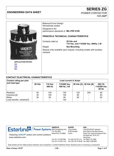
ENGINEERING DATA SHEET<strong>SERIES</strong> <strong>ZG</strong>POWER CONTACTOR145 AMPBalanced-Force DesignHermetically sealedDesigned to theperformance standards of MIL-PRF-6106PRINCIPLE TECHNICAL CHARACTERISTICSContacts rated at 28 Vdc and115 Vac, and 115/200 Vac, 400Hz, 3 ØWeightSee MountingSpecial units available upon request, including models with auxiliarycontacts.APPLICATION NOTES:101102007CONTACT ELECTRICAL CHARACTERISTICSContact rating per poleand load type28 Vdc 115 Vac400 HzLoad current in Amps115/200 Vac400 Hz, 3 Ø28 Vdc [3] 28 Vdc [8] DELTA115/200 Vac60 HzResistiveInductive [2]MotorLoad transfer, resistive[7]503030-14514590-145145901201208080-200---606060-Featuring LEACH © power and control solutionswww.esterline.comAMERICAS6900 Orangethorpe Ave.P.O. Box 5032Buena Park, CA 90622..Tel: (01) 714-736-7599Fax: (01) 714-670-1145EUROPE2 Rue Goethe57430 SarralbeFrance..Tel: (33) 3 87 97 31 01Fax: (33) 3 87 97 96 86ASIAUnits 602-603 6/F Lakeside 1No.8 Science Park West AvenuePhase Two, Hong Kong Science ParkPak Shek Kok, Tai Po, N.T.Hong KongTel: (852) 2 191 3830Fax: (852) 2 389 5803Data sheets are for initial product selection and comparison. Contact Esterline Power Systems prior to choosing a component.Date of issue: 01/07 - 128 - Page 1 of 5
COIL CHARACTERISTICS (Vdc)CODE A B C FVac400 Hz<strong>SERIES</strong> <strong>ZG</strong>N [5] Y [8] YN[8]Nominal operating voltage 28 12 6 115 28 28 28Maximum operating voltage 29 14.5 7.3 124 29 29 29Maximum pickup voltage- Nominal 18 9 4.5 90 18 18 18- High temp test 20 10 5 95 20 20 20- Continuous current test 22.5 11 5.7 100 22.5 22.5 22.5Drop-out voltage, maximum 7 4.5 2.5 30 7 7 7Coil resistance in Ohms ±10% at +25° C 113 28 7 - 113 - -Coil current Amp max. @ Nom. Volt. and +25° C 0.31 0.60 1.2 0.12 0.31 - -GENERAL CHARACTERISTICSTemperature rangeMinimum operating cycles (life) at rated load 50,000-55°C to +71°CMinimum operating cycles (life) at 25% rated load 100,000Dielectric strength at sea level- All circuits to ground and circuit to circuit 1500 Vrms- Coil to ground and Aux. contacts 1250 VrmsDielectric strength at altitudeInsulation resistance- Initial (500 Vdc) 100 M Ω min- After environmental tests (500 Vdc) 50 M Ω minSinusoidal vibration (55 to 1000 Hz)Shock (10-12 ms duration)700 Vrms (Main contacts)500 Vrms (Coil and Auxiliary contacts)10 G15 GMaximum contact opening time under vibration and shock 10 µsOperate time at nominal voltage (Including bounce)Release time at nominal voltage (Including bounce)-DC-ACRelease time at nominal voltage (Including bounce) : Economizer-DC60 ms max25 ms max (Economizer coil)40 ms max125 ms max35 ms maxDate of issue: 01/07 - 129 - Page 2 of 5
GENERAL CHARACTERISTICS CONTINUEDContact bounce at nominal voltageWeightOverloadRuptureAltitudeNUMBERING SYSTEM4 ms maxNoted1000 Amp @ 115/200 Vac, 400 Hz1400 Amp @ 115/200 Vac, 400 Hz15,240 m<strong>SERIES</strong> <strong>ZG</strong><strong>ZG</strong> - X 0 XRelay family______________________________________| | | |1-Mounting Style(A,B,Etc.)____________________________| | |2-Terminal & Circuit(1,2,3,Etc) __________________________| |3-Coil Voltage(A,B,C,F,N,Y,YN)________________________________|NOTES[1] Auxiliary contact rating.[2] Inductive load life, 20,000 cycles.[3] Ratings are for double break/make terminal type 6.[4] Alternate contact configurations and other special models available upon request. Please contact factory.[5] Back EMF suppression to 62 Volts Max.[6] Suitable for transfer between unsynchronized AC power sources at rating shown.[7] 200 Amps resistive, 25,000 cycles only, terminal style 6.[8] Economizer coils have a lower resistance primary coil for faster operate time. Once relay operates, the coilswitches to a higher resistance for lower power drain. Do not ramp up voltage on these coils.9. This series drawing is for general use only. Please consult factory for special requirements.Date of issue: 01/07 - 130 - Page 3 of 5
CONFIGURATION STYLES<strong>SERIES</strong> <strong>ZG</strong>COIL & AUXILIARY TERMINALS.138-32 UNC-2A, STUDNUT, .138-32 UNC-2B X 1/4 X 3/32STEEL CAD PLATELOCKWASHER, MS35338-41(STEEL)FLATWASHER, AN960-6 (STEEL)2.875POWER TERMINALS.250-28 UNF-2A, STUDNUT, .250-28 UNF-2B X 3/8 X 3/16STEEL CAD PLATELOCKWASHER, MS35338-44(STEEL)FLATWASHER, AN960-416L(STEEL)+.010.218 DIA-.0054 PLACESPOWER TERMINALS.250-28 UNF-2A, STUDNUT, .250-28 UNF-2B X 3/8 X 3/16STEEL CAD PLATELOCKWASHER, MS35338-44(STEEL)FLATWASHER, AN960-416L(STEEL)4.75 MAX3.937+.010.218 DIA-.0054 PLACESCONNECTOR 53.42SQUARE 2.875X1X23.65 DIAMAX2.8433.66MAX.562 DIA LUG SEAT TYP.645 MAX LUG DIA.312 R WRENCHCLEARANCE.562 DIA LUG SEAT TYP.645 MAX LUG DIAKEYWAY.265 R WRENCHCLEARANCE.62 ±.06.62 ±.06.62 ±.06NAMEPLATE4.28MAX2.58 ±.063.36 ±.06SCHEMATIC3.39 ±.06.62 ±.062.61 ±.063.15 ±.064.28MAXNAMEPLATE(THIS SIDE)SCHEMATIC(FARSIDE).09MOUNTING STYLE AUNPAINTED(2 MTG HOLES)WEIGHT: 2 LB MAXIMUMWEIGHT IS DEPENDENT UPON CONFIGURATION REQUIRED.PLEASE CONSULT FACTORY..0MOUNTING STYLE BWEIGHT: 2 LB 12 OZ MAXIMUMWEIGHT IS DEPENDENT UPON CONFIGURATION REQUIRED.PLEASE CONSULT FACTORY.MOUNTING STYLE HWEIGHT: 2 LB 8 OZ MAXIMUM3.94 MAX3.125MOUNTING STYLE KWEIGHT: 2 LB 13 OZ MAXIMUM.218 +.010 -.005 DIA4 MTG HOLESC3B3A3.594 REF DIA TYPMTG HOLE CLEARANCETERMINAL BARRIERMTG NUT2 PLACES3.3754.19MAX5.50MAX5.06MAX 4.28A2 B2 C2TERMINAL BARRIERSHOWN WITHOUTTOP FOR CLARITY.218 MTG HOLE4 PLACES1.50 REFC1B1A15CONNECTOR3.1253.89 MAXSTUD, .138-32 UNC-2ANUT, .138-32 UNC-2B X 1/4 X 3/32STEEL CAD PLATELOCKWASHER, MS35338-41(STEEL)FLATWASHER, AN960-6 (STEEL)2 EACH REQUIREDSTUD, .250 X 28 UNF-2A X 3/8 X 3/16STEEL CAD PLATELOCKWASHER, MS35338-44 (STEEL)FLATWASHER, AN960-416L (STEEL)6 EACH REQUIREDTERMINAL BARRIER ASSYSTUD, .250 X 28 UNF-2ANUT, .250 X 28 UNF-2B X 3/8 X 3/16STEEL CAD PLATELOCKWASHER, MS35338-44FLATWASHER, AN960-416L9 EACH REQUIREDNAMEPLATE (NEAR SIDE)CIRCUIT DIAGRAM (FAR SIDE).65 ±.0323.70MAX23.15MAX1.884.00MAX 3.78MAX3.13 ±.032.86 MAXCIRCUIT DIAGRAM1.88CONNECTOR5NAMEPLATECOIL CIRCUIT CONFIGURATION3 4NOTES:1 CAN BE DELETED.+X1+X1+X1+X12 MAXIMUM DIMENSIONS CAN BE REDUCED BY .500 INCH.-X2-X2-X2-X23 POLARITY INDICATION APPLIES TO D.C. COILS ONLY.STANDARD"A, B, C & F" COILSTANDARDWITHCOIL SUPPRESSION"N" COILECONOMIZER COIL"Y" COILStandard Tolerance: .XX ±.76, .XXX ±.25mmECONOMIZER COILWITHCOIL SUPPRESSION"YN" COIL4 COIL TERMINALS MAY BE IDENTIFIED ASA-B OR X1-X2.5 CIRCULAR CONNECTOR MS-STYLE OR EQUIVALENTDate of issue: 01/07 - 131 - Page 4 of 5
FEDTERMINAL CONFIGURATION AND CIRCUIT DIAGRAMS<strong>SERIES</strong> <strong>ZG</strong>TERMINAL TYPE 13 PDTC3C2C1B3B2B1A3+X1-X2A1A2A3B1B2B3C1C2C3TERMINAL TYPE 23 PST-N.O.C2C1B2B13+X1-X2A1A2B1B2C1C2TERMINAL TYPE 33 PST-N.O. WITHSPST-N.O. & SPST-N.C.AUXILIARY CONTACTS12112322C232+X1-X2A123A2B1B2C122C211121A2A1+X1-X2+1A2A1+X1-X2+87.38 MAXC1B2B1A287.38 MAXA1TERMINAL TYPE 43 PDT WITH SPST-N.O.AUXILIARY CONTACTTERMINAL TYPE 53 PDT WITH SPST-N.C.AUXILIARY CONTACT1+X1-X2+211211C3C2C1B3B2B1A3A2A1+X1-X22322C3C2C1B3B2B1A3A2A1+ +X11-X2++X1-X2A1A2A3B1B2B3C1C2C3*SEE CIRCUIT DIAGRAM FOR AUX 12CONTACT TERMINAL IDENTIFICATION**22A3A1+X11-X2TERMINAL TYPE 6SPDT-DOUBLE BREAK/MAKEWITH SPST-N.O. & SPST-N.C.AUXILIARY CONTACTS+21123A4A2487.38 MAX+X1-X2A123A3A222A41112TERMINAL TYPE 73 PDT WITH 2 PDTAUXILIARY CONTACTSTERMINAL TYPE 83 PDT WITH 4 PDTAUXILIARY CONTACTSHPNC3B3A32GFEDCC32MJKLHGFEG AHBCB2 C2A2C2C1B3DCC3C2C1 B1 A1B2B1A3C1B3B2B1A2A1A3A2A11+A-B++A-B+1POLARITY INDICATION APPLIES TO D.C. COILS ONLY2AUXILIARY CONTACT RATING28 VDC OR 115 VACTERMINAL TYPE 9IS A GENERAL CATEGORY USED FOR ALL TERMINALTYPES NOT ILLUSTRATED. FOR OTHER VARIATIONS OFTERMINAL CONFIGURATIONS-PLEASE CONTACT FACTORY.RESISTIVEINDUCTIVELAMPBOUNCE AT NOMINAL VOLTAGEOTHER AUXILIARY CONTACT FORMS AVAILABLE,INCLUDING LOW LEVEL CAPACITY3AVAILABLE IN "A" AND "H" MOUNTING5 AMP3 AMP1 AMP.004 SEC MAXAVAILABLE IN "A" AND "B" MOUNTINGNOTE: Although all configuration and/or terminal type options are available, some combinations may require a setup charge and besubject to minimum order size.4Date of issue: 01/07 - 132 - Page 5 of 5
Application notes N°101DERATING OF CONTACTS FOR DC VOLTAGESABOVE NOMINAL RATINGTo establish a standard for the derating of relay contacts is, at best, a subjective practice. Limitations are governed by the typeof relay, contact gap, maximum voltage capabilities of the relay contact system, and the contact material.The most common method is to derate the contacts by use of the Power Formula, using the known current and voltage.This method is valid only for Resistive Loads, and is an approximation only; keeping in mind the limitations mentioned above.Power = IE (Current x Voltage)I 2 E 2 = 2/3 I 1 E 1Example:A designer is working with a 55 volt DC system and has a relay rated at 10 amps resistive at 28 volts DC.What is the maximum current that can be switched at 55 Vdc.I 1 = 10 AmperesE 1 = 28 VDCE 2 = 55 VDCI 2 = ? (Current ratings at 55 VDC Resistive)I 2 E 2 = 2 I 1 E 1 /3I 2 = 2 I 1 E 1 /E 2 3= 2 (10 x 28)/55 x 3= 560/165I 2 = 3.4 Amperes at 55VDCIn addition, the user should always be concerned about the following:1. Derating contacts that are rated for less than 10 Amperes at nominal voltage.2. Derating contacts for use in system voltages above 130 Volts DCDate of issue: 6/00 - 14 - Page 1 of 1
Application notesN°102RELAYS AND TEMPERATURE VARIATIONSMost relay parameters are specified as maximum values over the rated temperature range of the specific relay. Users oftenfind that key parameters differ significantly at ambient temperature (20-25°C) and sometimes fall into the trap of specifyingtheir system around these ambient parameters. Additionally the actual temperature experienced by the relay can be far inexcess of existing ambient temperatures due to the heat generated by the coil current and the contact load. Figure 1 is thesummary of temperature effects on relay electrical characteristics.Temperature Resistance CurrentOperatingVoltageReleaseVoltageOperate TimeRelease TimeIncrease UP DOWN UP UP UP UPDecrease DOWN UP DOWN DOWN DOWN DOWNFig. 1The following formulas are sometimes useful in calculating the effects shown above.1. Change in coil resistance due to change of ambient temperature can be calculated by the following formula.R = R 20 [1 + .0039 (T-20)]Where: R = Coil resistance at given temperatureR 20 = Coil resistance at 20°CT = °C Ambient temperature"Rule of Thumb" : For each 10°C change of temperature, coil resistance will change approximately 4%.2. High and low temperature pick up voltage:E 2 = E 1 K 2,Where: E 2 = Pick Up Voltage at T 2 temperatureE 1 = Pick Up Voltage at 20°CK 2 = Coefficient of correction found on the graph in Fig. 2 at T 2Date of issue: 6/00 - 15 - Page 1 of 2
3. Calculation of coil temperature rise when R initial and R final are known:Delta T = (234.5 + T 1 ) (R 2 /R 1 - 1)Delta T = Temperature rise (°C)T 1 = Initial temperature (°C)R 1 = Initial resistance (Ohms)R 2 = Final resistance (Ohms)R 2 = K 2 R 1Temperature can also be found by making the R 2 /R 1 ratio = thecoefficient of correction graph in Fig. 2, and then finding the corresponding temperature.TEMPERATURE CORRECTION CHART FOR RESISTANCEFig. 2EXAMPLE:Catalog indicates coil resistance of 290 ohm at 25°C. What is the value at 125°C?From the chart: 290 x 1.39 = 403.31 Ohms.Date of issue: 6/00 - 16 - Page 2 of 2
Application notes N°007SUPPRESSOR DEVICES FOR RELAY COILSThe inductive nature of relay coils allows them to create magnetic forces which are converted to mechanical movements tooperate contact systems. When voltage is applied to a coil, the resulting current generates a magnetic flux, creatingmechanical work. Upon deenergizing the coil, the collapasing magnetic field induces a reverse voltage (also known as backEMF) which tends to maintain current flow in the coil. The induced voltage level mainly depends on the duration of thedeenergization. The faster the switch-off, the higher the induced voltage.All coil suppression networks are based on a reduction of speed of current decay. This reduction may also slow down theopening of contacts, adversly effecting contact life and reliability. Therefore, it is very important to have a clear understandingof these phenomena when designing a coil suppression circuitry.Typical coil characteristicsOn the graph below, the upper record shows the contacts state. (High level NO contacts closed, low level NC contactsclosed, intermediate state contact transfer). The lower record shows the voltage across the coil when the current is switchedoff by another relay contact.The surge voltage is limited to -300V by the arc generated across contact poles. Discharge duration is about 200mircoseconds after which the current change does not generate sufficient voltage. The voltage decreases to the point wherethe contacts start to move, at this time, the voltage increases due to the energy contained in the NO contact springs. Thevoltage decreases again during transfer, and increases once more when the magnetic circuit is closed on permanentmagnet.Operating times are as follows:Time to start the movement 1.5msTotal motion time 2.3msTransfer time 1.4msContact StateDate of issue: 6/00 - 8 - Page 1 of 4
Types of suppressors:Passive devices.The resistor capacitor circuitIt eliminates the power dissipation problem, as well as fast voltage rises. With a proper match between coil and resistor,approximate capacitance value can be calculated from:C = 0.02xT/R, whereT = operating time in millisecondsR = coil resistance in kiloOhmsC = capacitance in microFaradsThe series resistor must be between 0.5 and 1 times the coil resistance. Special consideration must be taken for thecapacitor inrush current in the case of a low resistance coil.The record shown opposite is performed on the same relay as above. The operation time becomes:- time to start the movement 2.3ms- transfer time 1.2msThe major difficulty comes from the capacitor volume. In our example of a relay with a 290 Ω coil and time delay of 8 ms, acapacitance value of C=0.5 uF is found. This non polarized capacitor, with a voltage of 63V minimum, has a volume of about1cm 3 . For 150V, this volume becomes 1.5 cm 3 .Date of issue: 6/00 - 9 - Page 2 of 4
The bifilar coilThe principle is to wind on the magnetic circuit of the main coil a second coil shorted on itself. By a proper adaptation of theinternal resistance of this second coil it is possible to find an acceptable equilibrium between surge voltage and reduction ofthe opening speed. To be efficient at fast voltage changes, the coupling of two coils must be perfect. This implies embeddedwindings. The volume occupied by the second coil reduces the efficiency of the main coil and results in higher coil powerconsumption. This method cannot be applied efficiently to products not specifically designed for this purpose.The resistor (parallel with the coil)For efficient action, the resistor must be of the same order of magnitude as the coil resistance. A resistor 1.5 times the coilresistance will limit the surge to 1.5 times the supply voltage. Release time and opening speed are moderately affected. Themajor problem is the extra power dissipated.Semi-conductor devicesThe diodeIt is the most simple method to totally suppress the surge voltage. It has the major disadvantage of the higher reduction ofcontact opening speed. This is due to the total recycling, through the diode, of the energy contained in the coil itself. Thefollowing measurement is performed once again on the same relay. Operation times are given by the upper curve:- time to start the movement 14ms- transfer time 5msThese times are multiplied by a coefficient from 4 to 8.The lower curve shows the coil current. The increase prior to NO contact opening indicates that the contact spring dissipatesits energy. At the opening time the current becomes constant as a result of practically zero opening speed.Due to this kind of behavior, this type of suppression must be avoided for power relays. For small relays which have to switchlow currents of less than 0.2 A, degradation of life is not that significant and the method may be acceptable.Date of issue: 6/00 - 10 - Page 3 of 4
The diode + resistor networkIt eliminates the inconvenience of the resistor alone, explained above, and it limits the action of a single diode. It is nowpreferred to used the diode + zener network.The diode + zener networkLike the resistor, the zener allows a faster decurrent decay. In addition it introduces a threshold level for current conductionwhich avoids the recycling of energy released during contact movement.The lower curve on the opposite record demonstrates those characteristics. Voltage limitation occurs at 42V. The twovoltages spikes generated by internal movement are at lower levels than zener conduction. As a result, no current is recycledin the coil.The opening time phases are as follows:- time to start the movement 2.6ms- total motion time 2.4ms- transfer time 1.4msThe release time is slightly increased. The contacts' opening speed remains unchanged.Date of issue: 6/00 - 11 - Page 4 of 4