MS24568-A1 - Leach International
MS24568-A1 - Leach International
MS24568-A1 - Leach International

Create successful ePaper yourself
Turn your PDF publications into a flip-book with our unique Google optimized e-Paper software.
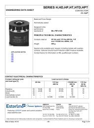
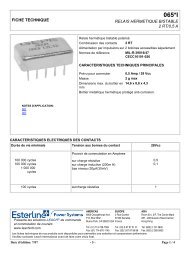
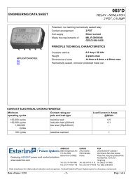
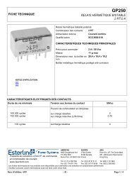
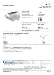
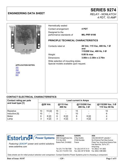
ENGINEERING DATA SHEETSERIES 9274RELAY - NONLATCH4 PDT, 15 AMPHermetically sealedContact arrangementDesigned to theperformance standards of4 PDTMIL-PRF-6106PRINCIPLE TECHNICAL CHARACTERISTICSAPPLICATION NOTES:101102103D007Contacts rated at28 Vdc; 115 Vac, 400 Hz, 1 Øand115/200 Vac, 400 Hz, 3 ØWeight0.80 lb maxDimensions3.00in x 2.30in x 2.70inWide selection of mounting styles.Special models available upon request.CONTACT ELECTRICAL CHARACTERISTICSContact rating per poleand load type [1]@28 Vdc @115 Vac400 HzLoad current in Amps@115/200 Vac400 Hz, 3 Ø@115/200 Vac, 3 Ø115 Vac 60 HzResistiveInductive [5]MotorLamp10106315 [2]-8 [2]4 [2]151063--8 [2]4 [2]151063--8 [2]4 [2]10642Featuring LEACH © power and control solutionswww.esterline.comAMERICAS6900 Orangethorpe Ave.P.O. Box 5032Buena Park, CA 90622..Tel: (01) 714-736-7599Fax: (01) 714-670-1145EUROPE2 Rue Goethe57430 SarralbeFrance..Tel: (33) 3 87 97 31 01Fax: (33) 3 87 97 96 86ASIAUnits 602-603 6/F Lakeside 1No.8 Science Park West AvenuePhase Two, Hong Kong Science ParkPak Shek Kok, Tai Po, N.T.Hong KongTel: (852) 2 191 3830Fax: (852) 2 389 5803Data sheets are for initial product selection and comparison. Contact Esterline Power Systems prior to choosing a component.Date of issue: 01/07 - 129 - Page 1 of 5
RELAY NUMBERING SYSTEM SERIES 9274TERMINAL MOUNTING 28 VDC SUPPRESSED28 VDC [4]115 VAC, 400 HZ [3] 115 VAC, 60 HZSolderterminalFlat & piercedStud 9274-5770 9274-10380 9274-5771 9274-5772Screw Bracket 9274-6205<strong>MS24568</strong>-D1*Specials available upon request, please contact factory.9274-10381 9274-6667<strong>MS24568</strong>-<strong>A1</strong>9274-55699274-10291<strong>MS24568</strong>-A2NOTES[1] Standard intermediate current test applicable.[2] Values beyond applicable military specification requirements.[3] May be used on 115 Vac, 60 Hz if maximum ambient temperature is limited to +85°C.[4] Coils have back EMF suppression to 42 Volts.[5] Inductive load life is 20 percent of rated resistive load life.6. Applicable military specification: MIL-PRF-6106.Date of issue: 01/07 - 131 - Page 3 of 5
CONFIGURATION SERIES 9274MOUNTING STYLE 11.807MAX+.031.375-.000SLOT.065 X .1256-32 UNC-2A4 MTG STUDS2.062 MAX1.500 ±.010.080 DIATERMINAL12 PLACES2.062 MAX1.500 ±.010ST D. T OL . ± .031.040 DIATERMINAL2 PLACESMODEL NUMBER9274-57709274-57719274-57729274-10380WEIGHT (MAX).70 LB.73 LB.73 LBMOUNTING STYLE 2.560 ±.0302.700 MAX1.2501.000NAMEPLATE+.012.173 -.006 DI<strong>A1</strong>2 MTG HOLESDRAIN HOLE LOCATEDCENTRALLY EACH SIDEOF HEADER3.000 MAX2.625.190±.020RAISED TERMINAL MARKINGSON PANEL+.1102.000-.100AB3A2B212.300 MAX1.2501.000<strong>A1</strong>C3X1C2X2D2B3D12.000 +.110-.100CD.560 ±.03013ST D. T OL . ± .005AN508-6-5, SCREWMS35338-98, LOCKWASHERAN961-6, WASHER14 EACH REQUIRED OR CAPTIVE SCREW SET.410 MIN TYP14 PLACESMODEL NUMBER WEIGHT (MAX)9274-6205 .73 LB9274-6667 .73 LB9274-5569 .80 LB9274-10381 .73 LB9274-10291 .80 LBDate of issue: 01/07 - 132 - Page 4 of 5
MOUNTING DATA SERIES 9274SCHEMATIC DIAGRAMD2C2B2A2D3D1C3C1B3B1A3<strong>A1</strong>X1MOUNTING DIMENSIONSX21.500.152 DIA4 HOLES1.203 ±.0101.500SOLDER TERMINALS.1402.6251.0001.0001.2501.250STD. TOL.: ± .005.560 ±.030SIDE MOUNTINGTOP MOUNTING.560 ±.030Date of issue: 12/06 - 133 - Page 5 of 5
Application notes N°101DERATING OF CONTACTS FOR DC VOLTAGESABOVE NOMINAL RATINGTo establish a standard for the derating of relay contacts is, at best, a subjective practice. Limitations are governed by the typeof relay, contact gap, maximum voltage capabilities of the relay contact system, and the contact material.The most common method is to derate the contacts by use of the Power Formula, using the known current and voltage.This method is valid only for Resistive Loads, and is an approximation only; keeping in mind the limitations mentioned above.Power = IE (Current x Voltage)I 2 E 2 = 2/3 I 1 E 1Example:A designer is working with a 55 volt DC system and has a relay rated at 10 amps resistive at 28 volts DC.What is the maximum current that can be switched at 55 Vdc.I 1 = 10 AmperesE 1 = 28 VDCE 2 = 55 VDCI 2 = ? (Current ratings at 55 VDC Resistive)I 2 E 2 = 2 I 1 E 1 /3I 2 = 2 I 1 E 1 /E 2 3= 2 (10 x 28)/55 x 3= 560/165I 2 = 3.4 Amperes at 55VDCIn addition, the user should always be concerned about the following:1. Derating contacts that are rated for less than 10 Amperes at nominal voltage.2. Derating contacts for use in system voltages above 130 Volts DCDate of issue: 6/00 - 14 - Page 1 of 1
Application notesN°102RELAYS AND TEMPERATURE VARIATIONSMost relay parameters are specified as maximum values over the rated temperature range of the specific relay. Users oftenfind that key parameters differ significantly at ambient temperature (20-25°C) and sometimes fall into the trap of specifyingtheir system around these ambient parameters. Additionally the actual temperature experienced by the relay can be far inexcess of existing ambient temperatures due to the heat generated by the coil current and the contact load. Figure 1 is thesummary of temperature effects on relay electrical characteristics.Temperature Resistance CurrentOperatingVoltageReleaseVoltageOperate TimeRelease TimeIncrease UP DOWN UP UP UP UPDecrease DOWN UP DOWN DOWN DOWN DOWNFig. 1The following formulas are sometimes useful in calculating the effects shown above.1. Change in coil resistance due to change of ambient temperature can be calculated by the following formula.R = R 20 [1 + .0039 (T-20)]Where: R = Coil resistance at given temperatureR 20 = Coil resistance at 20°CT = °C Ambient temperature"Rule of Thumb" : For each 10°C change of temperature, coil resistance will change approximately 4%.2. High and low temperature pick up voltage:E 2 = E 1 K 2,Where: E 2 = Pick Up Voltage at T 2 temperatureE 1 = Pick Up Voltage at 20°CK 2 = Coefficient of correction found on the graph in Fig. 2 at T 2Date of issue: 6/00 - 15 - Page 1 of 2
3. Calculation of coil temperature rise when R initial and R final are known:Delta T = (234.5 + T 1 ) (R 2 /R 1 - 1)Delta T = Temperature rise (°C)T 1 = Initial temperature (°C)R 1 = Initial resistance (Ohms)R 2 = Final resistance (Ohms)R 2 = K 2 R 1Temperature can also be found by making the R 2 /R 1 ratio = thecoefficient of correction graph in Fig. 2, and then finding the corresponding temperature.TEMPERATURE CORRECTION CHART FOR RESISTANCEFig. 2EXAMPLE:Catalog indicates coil resistance of 290 ohm at 25°C. What is the value at 125°C?From the chart: 290 x 1.39 = 403.31 Ohms.Date of issue: 6/00 - 16 - Page 2 of 2
Application notesN°103DCURVES FOR DC VOLTAGES ABOVE NORMAL RATING: RESISTIVE LOAD ONLY(without arc suppression)Date of issue: 6/00 - 19 - Page 1 of 1
Application notes N°007SUPPRESSOR DEVICES FOR RELAY COILSThe inductive nature of relay coils allows them to create magnetic forces which are converted to mechanical movements tooperate contact systems. When voltage is applied to a coil, the resulting current generates a magnetic flux, creatingmechanical work. Upon deenergizing the coil, the collapasing magnetic field induces a reverse voltage (also known as backEMF) which tends to maintain current flow in the coil. The induced voltage level mainly depends on the duration of thedeenergization. The faster the switch-off, the higher the induced voltage.All coil suppression networks are based on a reduction of speed of current decay. This reduction may also slow down theopening of contacts, adversly effecting contact life and reliability. Therefore, it is very important to have a clear understandingof these phenomena when designing a coil suppression circuitry.Typical coil characteristicsOn the graph below, the upper record shows the contacts state. (High level NO contacts closed, low level NC contacts closed,intermediate state contact transfer). The lower record shows the voltage across the coil when the current is switched off byanother relay contact.The surge voltage is limited to -300V by the arc generated across contact poles. Discharge duration is about 200mircoseconds after which the current change does not generate sufficient voltage. The voltage decreases to the point wherethe contacts start to move, at this time, the voltage increases due to the energy contained in the NO contact springs. Thevoltage decreases again during transfer, and increases once more when the magnetic circuit is closed on permanent magnet.Operating times are as follows:Time to start the movement 1.5msTotal motion time 2.3msTransfer time 1.4msContact StateDate of issue: 6/00 - 8 - Page 1 of 4
Types of suppressors:Passive devices.The resistor capacitor circuitIt eliminates the power dissipation problem, as well as fast voltage rises. With a proper match between coil and resistor,approximate capacitance value can be calculated from:C = 0.02xT/R, whereT = operating time in millisecondsR = coil resistance in kiloOhmsC = capacitance in microFaradsThe series resistor must be between 0.5 and 1 times the coil resistance. Special consideration must be taken for thecapacitor inrush current in the case of a low resistance coil.The record shown opposite is performed on the same relay as above. The operation time becomes:- time to start the movement 2.3ms- transfer time 1.2msThe major difficulty comes from the capacitor volume. In our example of a relay with a 290 Ω coil and time delay of 8 ms, acapacitance value of C=0.5 uF is found. This non polarized capacitor, with a voltage of 63V minimum, has a volume of about1cm 3 . For 150V, this volume becomes 1.5 cm 3 .Date of issue: 6/00 - 9 - Page 2 of 4
The bifilar coilThe principle is to wind on the magnetic circuit of the main coil a second coil shorted on itself. By a proper adaptation of theinternal resistance of this second coil it is possible to find an acceptable equilibrium between surge voltage and reduction ofthe opening speed. To be efficient at fast voltage changes, the coupling of two coils must be perfect. This implies embeddedwindings. The volume occupied by the second coil reduces the efficiency of the main coil and results in higher coil powerconsumption. This method cannot be applied efficiently to products not specifically designed for this purpose.The resistor (parallel with the coil)For efficient action, the resistor must be of the same order of magnitude as the coil resistance. A resistor 1.5 times the coilresistance will limit the surge to 1.5 times the supply voltage. Release time and opening speed are moderately affected. Themajor problem is the extra power dissipated.Semi-conductor devicesThe diodeIt is the most simple method to totally suppress the surge voltage. It has the major disadvantage of the higher reduction ofcontact opening speed. This is due to the total recycling, through the diode, of the energy contained in the coil itself. Thefollowing measurement is performed once again on the same relay. Operation times are given by the upper curve:- time to start the movement 14ms- transfer time 5msThese times are multiplied by a coefficient from 4 to 8.The lower curve shows the coil current. The increase prior to NO contact opening indicates that the contact spring dissipatesits energy. At the opening time the current becomes constant as a result of practically zero opening speed.Due to this kind of behavior, this type of suppression must be avoided for power relays. For small relays which have to switchlow currents of less than 0.2 A, degradation of life is not that significant and the method may be acceptable.Date of issue: 6/00 - 10 - Page 3 of 4
The diode + resistor networkIt eliminates the inconvenience of the resistor alone, explained above, and it limits the action of a single diode. It is nowpreferred to used the diode + zener network.The diode + zener networkLike the resistor, the zener allows a faster decurrent decay. In addition it introduces a threshold level for current conductionwhich avoids the recycling of energy released during contact movement.The lower curve on the opposite record demonstrates those characteristics. Voltage limitation occurs at 42V. The two voltagesspikes generated by internal movement are at lower levels than zener conduction. As a result, no current is recycled in thecoil.The opening time phases are as follows:- time to start the movement 2.6ms- total motion time 2.4ms- transfer time 1.4msThe release time is slightly increased. The contacts' opening speed remains unchanged.Date of issue: 6/00 - 11 - Page 4 of 4