309-364 Installation Instructions - Zipper's Performance Products
309-364 Installation Instructions - Zipper's Performance Products
309-364 Installation Instructions - Zipper's Performance Products
- No tags were found...

You also want an ePaper? Increase the reach of your titles
YUMPU automatically turns print PDFs into web optimized ePapers that Google loves.
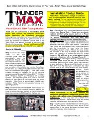
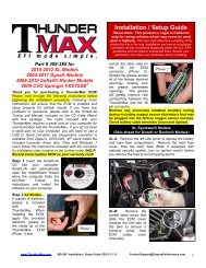
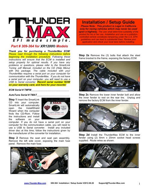
Part # <strong>309</strong>-<strong>364</strong> for XR1200® ModelsThank you for purchasing a ThunderMax ECM!Please read through the following instructions beforebeginning the installation procedure. Following theseinstructions will ensure that the ECM is installed andsetup properly for optimal results. If you have anyproblems or questions, please refer to the SmartLinkTuning .pdf Manual, included on the CD (Help Menu)with this package. The cable included with yourThunderMax requires a serial port on your computer forcommunication with the ThunderMax. If you do not havea serial port on your computer, you will need to use aUSB to Serial converter. Record serial number NOWon your warranty card, and here for your records!<strong>Installation</strong> / Setup GuidePlease Note: This product is Legal in Californiaonly for racing vehicles which may never be usedupon a highway. The user shall determine suitability of theproduct for his or her use. <strong>Installation</strong> and use on a pollutioncontrolledvehicle constitutes tampering under the U.S. EPAguidelines and can lead to substantial fines. Review yourapplication and check your local laws before installing.Step 2a Remove the (3) bolts that attach the steelframe bracket to the frame, exposing the factory ECM.ECM Serial # TMFM____________________________AutoTune Serial # TMAT________________________Step 1 Insert the SmartLinkCD into your computer.SmartLink will automaticallyopen the InstallShieldWizard when the computerfinds the CD-Rom. Followthe instructions and installthe software on yourcomputer. If you do not have a serial port on yourcomputer for the communication cable, you will need touse a USB to Serial converter. Install any includeddriver disc at this time; follow the instructions given bythe manufacturer of the converter for installation.Step 2 Remove the seat and seat pan assembly.Remove the left side cover, exposing the main fusepanel. Remove the main fuse.Step 2c Remove the lower inner fender bolt and allowthe inner fender to rest on the rear tire. Unplug andremove the factory ECM from the inner fender.Step 2d Install the ThunderMax ECM to the innerfender using (2) 6mm x 20mm socket head screwssupplied. Route wires as shown.www.Thunder-Max.com <strong>309</strong>-<strong>364</strong> <strong>Installation</strong> / Setup Guide V2012.06.28 Support@Thunder-Max.com1
Step 2e Install ThunderMax Pigtail connector # <strong>309</strong>-324to 36 pin harness connector per connector instructions.Step 2i Route rear O 2 sensor and AutoTune powerharness between left frame rail and oil tank. Install O 2sensor into rear exhaust pipe and connect plug. PlugAutoTune power harness into 4-pin (gray) data port plugas shown.Step 2f Carefully connect ThunderMax ECM to the 36pin harness plug, ensuring that the harness plug weatherseal does not roll out or get pinched during assembly;firmly press the plug and ECM together until latchedcompletely.Step 2g Unplug and remove factory O 2 sensors; usesupplied caps to cover harness terminal connectors.Route front sensor harness through gap betweenswingarm and frame. It’s a tight fit; turn connector sothat locking tab boss faces forward and open plug areafaces to left side of bike and it will slide through. Feedconnector under transmission.Step 2j Route Pigtailharness connector totop of frame triangle infront of left side shockfor easy access underleft frame cover. Remountinner fender andsteel frame bracket withECM attached.Step 2k Secure harnesses away from hot or movingparts using supplies wire ties. Re-install main fuse, seatand seat pan/fender assembly.Step 2h Route front O 2 sensor from under transmissionthrough gap between lower frame rail and primary cover,along frame rail to front exhaust pipe. Carefully wind O 2sensor harness 3-4 turns counterclockwise beforeinstalling into exhaust pipe; turn clockwise whileinstalling to unwind harness. Connect harness plug.Oxygen Sensor <strong>Installation</strong> NotesThe wide band sensors are longer than the factorysensors. <strong>Installation</strong> of the wide band sensors intofactory headpipes presents no clearance problems,however, some aftermarket pipes may require exhaustpipe modification or sensor bung relocation forinterference-free installation. The sensors must mountfreely without contacting surrounding components. Ifthis is not possible, do not attempt to bend ormodify the sensor in any way as it is a sensitiveelectronic component and will be damaged if you do.Modify the pipe if required for clearance. Weld-in bungsare available from many industry sources in straight orangled style if current bungs present clearance issues.Bungs should be located no more than 3-4” from thehead/pipe connection (for ideal location, refer to thefactory location on 2007-up models). Chase the threadsafter welding with an 18 x 1.5mm tap (available fromauto parts stores) and verify that the oxygen sensorthreads in easily without the pipe wall interfering with thesensor tip. After installation, route the sensor harnesswww.Thunder-Max.com <strong>309</strong>-<strong>364</strong> <strong>Installation</strong> / Setup Guide V2012.06.28 Support@Thunder-Max.com2
away from the engine and along the frame whenpossible, above the lowest frame point to avoid thepossibility of dragging ground during operation. Avoidrouting harnesses where engine movement or movingparts can contact and damage the harnesses orconnector plugs. Tie the harnesses to the frame orexisting component harnesses, taking care to avoidcontact with any vibrating component that may chaff thesheathing or wires. Some disassembly of bikecomponents may be required for best harness routing.Step 3 Load a Base Map to your SmartLink software.Selecting a base map for your ThunderMax is easythanks to the filtering system in the SmartLink software.Open SmartLink; from the toolbar choose [EFI Maps][EFI Map Listings / Definitions]. You should firstupdate the Map Definitions file to ensure you have thelatest available maps. Close the [Base MapDefinitions] window, then click the [Check Internet ForUpdates] button (requires internet connection; followprompts). After updating, select [Select BaseMap]..All maps that do not match your selection will be filteredfrom the screen.Second, place your curser over the ‘Throttle’ columnand right click your match.Third, right-click the ‘Exhaust’ type that closest matchesyour application.Available base maps will be shown (if the [Clear Filters]button at the lower left of the screen is highlighted, clickit to clear filtered maps so all maps will be shown).Fourth, right click the ‘Muffler’ column if further definitionof the exhaust system is required (depends on exhaustapplication). Keep right-clicking the application columnsuntil you have located the best map match (in the caseof identical maps, choose the latest date). Highlight themap you’ve chosen (left-click; blue bar indicatesselected map) and click [Close] button. This brings youto the ‘Base Map Name Encoding’ page, from which youcan review the map parameters. Click the [LoadBaseMap] button to load the map into the software.Filter the maps to locate a base map that best matchesyour application by placing your curser first over any‘Engine Type’ that matches your engine and right-click it.From this page you can load the base map into thesoftware by clicking the [Load Base Map] button.[Close] this page to view the open map page.www.Thunder-Max.com <strong>309</strong>-<strong>364</strong> <strong>Installation</strong> / Setup Guide V2012.06.28 Support@Thunder-Max.com3
Step 4 From the ‘Tuning Maps’ Tree, click the + signnext to [Module Configuration], then double-click‘Basic Settings’. The basic settings page opens.Check to see if the [Speedo Cal] calibration settingmatches your year and model; if not, click the button,enter the correct value as shown, then click [Close].From the toolbar, click [File] [Write Module Maps andSettings], answer OK to the message that informs youthat you are about to overwrite the current map in themodule; the transfer bar appears during the map load.Step 7 Verify Module Settings. Before performing thisstep, clear any active Diagnostic Code readings. Whilelinked, from the Tuning Tree select [ModuleConfiguration] [Diagnostic Codes].Speedometer Calibration SettingsXR1200 2008-up 48750When the Diagnostic Codes window appears, select[Clear Diagnostic Codes]. After completing this step,select Basic Settings from the Module Configurationmenu and verify that the speedometer calibration iscorrect. After verifying these settings, click [Write BasicSettings]. If the installation is to be operated in closedloop mode (with AutoTune module), select[Configuration] from the toolbar menu and click[Closed Loop Configuration]. Verify that the [ClosedLoop Processing] and [AutoTune] boxes are checked√ on the left (module) side of the window.Step 5 Now you are ready to ‘Link’and ‘Write’ the map to the ECM.Attach the communication cablefrom your computer to theThunderMax pigtail harness,making certain that the cable isrouted away from any part of themotorcycle that generates heat.Special Note for International Model Bikes withActive Exhaust Enabled: If your bike is equipped witha working Active Exhaust Valve, you must unplug theactive exhaust harness before linking to the module, asthe AEV circuitry conflicts with the communicationstream. You can re-connect the harness after unlinking.If the stock exhaust has been changed, disregard thisstep. ThunderMax does not support active exhaustStep 6 To link to the module, turn the key switch to the“Ignition” position, making certain the “RUN / OFF”rocker switch (Kill Switch) on the handlebar controls is inthe “RUN” position.Select the “Link”Button in theSmartLink software.The button turnsgreen to indicate asuccessful link. Answer [No] to the “Do you wish toREAD the module map now” question at this time.IMPORTANT STEP BEFORE STARTINGNext, ‘Initialize’ the ThunderMax ECM. Initializingsynchronizes ‘home’ positions for the TPS and IAC, andis a required step any time battery power has beeninterrupted or established to the ThunderMax ECM.With the handlebar switch in the ‘ON’ position, cyclethe key switch on and off 3 times, leaving theignition on for 30 seconds, then off for 30 seconds,each cycle. DO NOT start the engine or move thethrottle during this process. After 3 on/off cycles, makecertain that the motorcycle is in neutral and start the bike2 times, letting it settle at idle for 10 seconds; the idleshould be smooth and steady. Some engines mayrequire several on/off engine starts to initialize properly.This initialization processmust be performed any timebattery power is interruptedto the module (after batteryservicing/winterization, etc).After initialization, shut off theengine, but stay linked forstep 8.www.Thunder-Max.com <strong>309</strong>-<strong>364</strong> <strong>Installation</strong> / Setup Guide V2012.06.28 Support@Thunder-Max.com4
Step 8 Before restarting the engine, from toolbar click[Monitoring] [Show Gauges]. The “Engine Speed”,“Engine Head Temp”, “IAC Position”, “AFR Front”, AFRRear” and “AFR Target” gauges are automaticallyformatted and are shown on the screen. Additionalgauges can be created if desired (see SmartLink TuningManual under Help menu), but the above gauges aremost helpful during initial set up. You may select anygauges that you deem important; if too many are chosenyour screen may appear cluttered.Step 9 Select the “Monitor” button to active the gauges.It is located beside the “Link” button and will turn greenwhen the monitor gauge functions are live. The gaugeswill be displayed if they were not already on the screen.Step 10 Now select the IAC Stops vs. EngineTemperature page from “IAC Curves” menu within thetuning tree. Strike thethe IAC position, the engine will idle above the idle rpmspecified in the idle speed vs. engine temperature page.If it determined that these automatic adjustments havenot resulted in satisfactory operation of the engine,consult the SmartLink Manual (available under the Helpsection of the toolbar), Section 3 (Tuning theThunderMax ECM) for further adjustment procedures.CLOSED LOOP PROCESSINGWhen equipped with AutoTune, your SmartLink softwarewill allow you to set Air/Fuel tuning parameters for yourThunderMax and its installed base map. To set theAutoTune Limits, go to the toolbar and click [Configure][Close Loop MODULE Settings].The Closed Loop Configuration dialog page opens; theright side shows the default MAP settings stored in theMAP file (settings are applied to the installed base mapduring the ‘Closed Loop Format’ conversion performedby SmartLink), while the left side shows what the moduleis currently set to (unadjusted, these settings will mirrorspacebar to show the actual values of the tuning block(use left/right arrow keys to move the block marker).Make certain that the motorcycle is in neutral and theengine is cold, and then start the engine. Once theengine idle is stable after 15- 20 seconds, select the“IAC-Auto” button (Idle Air Control Auto Adjustment).Allow the “IAC-Auto” function to run at idle until theengine head temperature reaches 275 degrees. Afterreaching temperature of 275 degrees, the “IAC-Auto”function automatically shuts off. You can terminate thisfunction at any time, and re-run it at a later time if youwish.Step 11 Unlink the SmartLink software from the ECM,turn off the ignition switch and remove thecommunication cable from the ThunderMax ECM. Usethe ‘Save As’ command to create a folder and save themap to your hard drive. The motorcycle is now ready tobe ridden. Several riding sessions that allow the engineto reach normal operating temperature should becompleted. During this process, the IAC virtual stops willautomatically be adjusted to the IAC target values setwithin the map’s basic settings. This featureautomatically adjusts how the engine comes back to thespecified idle speed. If the IAC stops are set too low, theengine will dip below the specified idle speed duringcertain transient conditions. If the IAC stops are aboveMAP’s settings).The un-highlighted left ‘MODULE’ side of the pageallows editing of those settings within the MODULE fortuning purposes, while unaffecting the MAP settings. Toedit module settings, click the [Link/Read (Module)]button (left side highlights/active). You can now editthese settings within the live module should you want tochange any of the settings from the MAP defaultsettings.Closed Loop Processing (Module) – Check [ON] toenable closed loop AutoTune processing. During closedloop processing, the ThunderMax module processesfeedback from the oxygen sensors to adjust the fuelwww.Thunder-Max.com <strong>309</strong>-<strong>364</strong> <strong>Installation</strong> / Setup Guide V2012.06.28 Support@Thunder-Max.com5
volume at all points by creating learned “offset” pointsfrom the installed ‘base map’ fuel points. The ‘static’base map is dynamically used by the ThunderMaxmodule and the AutoTune’s active (closed loop)feedback system. This system optimizes the fuel pointsto fit the target air/fuel ratio through ‘learned offsetpoints’. These ‘learned offset points’ are stored withinthe ThunderMax and are used in conjunction with thebase map. The ‘base map’ fuel points are not beingadjusted by either the AutoTune or ThunderMaxmodules.If AutoTune Closed Loop Processing is un-checked, fuelpoints will be adjusted to the last learned offset points, orif no learning has occurred, to the original base mappoints. Stored offset points remain within the module; inthe event that power is interrupted for any reason, thelearned offset points remain until re-learned or clearedunder the [Map Editing] toolbar menu.Air Fuel Ratio Override (Module) – A single TargetAFR setting can be applied using this command.Clicking this box and changing this number overridesALL ‘Air/Fuel Ratio vs. TPS’ pages at all RPM’s. Totarget specific Air/Fuel Ratio RPM ranges and throttlepositions, leave this box unchecked and edit theindividual ‘Air/Fuel-TPS @ RPM’ map pages locatedunder the [Tuning Maps] tree. Individual Air/Fueltargets are pre-set within the base map to provide agood balance between power and economy. Individualcell throttle position/rpm AFR targets can be viewed andadjusted on these pages. Use the left/right arrow keysto navigate the individual blocks (strike the spacebar toview the values); use the up/down arrow keys to adjustthe values. Click the [Monitor] button when linked liveand a vertical bar will show the actual throttle position.See the SmartLink manual for further tuning instructions.Idle Air Control Override (Module) - Check [OFF].This setting should not be checked on except fordiagnosing a particular type of supported problem orduring tuning on a load cell dyno. Changing this settingwill lead to starting and idling problems.Maximum CLP Offset (Module) – [Session (Module)]button sets the AFR maximum learning correction fromthe base map’s fuel setting per session by percentage(range is 0-10%). A ‘session’ is defined as the period oftime from engine on to engine off (per cycle).[Maximum (Module)] button sets the total AFRmaximum learning correction from the base map’s fuelsetting by percentage (regardless of number of sessions;range is 0-25%). Unless your application is aconsiderable mismatch to the installed base map, thedefault settings of 5 and 20 percent are sufficient formost AFR corrections.You should always pick the best possible map matchduring the selection of your base map. The theorybehind this is to reduce the range and time the closedloop system needs to learn offsets (corrections) for thetarget AFR. If your map selection is a poor match to theapplication, the amount of learning needed will besignificant. Review the parameters of your base map vs.available base maps under ‘Base Maps Listing’ toensure you have the best map match and the latestversion of the map.www.Thunder-Max.com <strong>309</strong>-<strong>364</strong> <strong>Installation</strong> / Setup Guide V2012.06.28 Support@Thunder-Max.com6
TIPS AND GENERAL INFORMATIONSeveral support features are located under the[Help] menu; some require an internetconnection.A comprehensive Tuning Manual in PDFformat is included on the CD for viewing andprinting from your desktop.When the SmartLink program is opened, itwill automatically retrieve and open the last mapthat was open.Any time you link to your motorcycle: Readthe map that is installed in the ThunderMaxECM by selecting [File] then [Read ModuleMaps and Settings] on the SmartLink toolbar.This will synchronize the map file loaded into theThunderMax ECM with the SmartLink software.2003 FLT/FLHT models: H-D® used 2 differentspeedometer calibrations during the extended2003 model production. Which calibration youmay need is easily identified by checking thepart number on the back of your factory ECM.Calibration 20480 is used if the part numberends in -03, while 4352 is used if the ECM p/nends in -02. If your turn signals don’t cancel ona 2003 model, try the alternate setting. 2007-up Big Twin models: There are twosettings in the [Module Configuration] [BasicSettings] page that should to be set to thefollowing to enable the 6 th gear indicator light tofunction:Final drive ratio [87; 84 for 06-07 Dyna®]Gear 6 Min TPS [40]. Sportster®, XR models: The [Main RelayLoc] must be set to “1” under the [BasicSettings] [Module Configuration] page, or theengine will not start.Accel Fuel is be used to tune throttle response(go to [Module Configuration] [Basic Settings]).AFR Correction vs. Engine Temperature pageis used to adjust cold start AFR’s. It is active yetshould be used with extreme caution. Anychanges made to this page affects all maps, atevery throttle position, every 256 RPM’s! SeeSmartLink Tuning Manual for procedures.AFR vs. Engine Temperature is active yet atthis time you should be discouraged frommaking any changes to this page.Air/Fuel-TPS @ RPM These pages reflectdesired targets of AFR to throttle position atevery 256 RPM. Example: if you desire a leanermixture for added fuel economy then you caneasily make multi-tiered AFR targets at specificthrottle positions and RPM’s that will be learnedduring closed loop processing.During warm-up, the AFR on both cylinders willbe richer than the target AFR at normaloperating temperatures; this is a normal part ofthe warm-up map. AutoTune and its targets areinactive below 200 degrees.Target air/fuel ratios can be viewed on theAir/Fuel-TPS @ RPM pages. When thesepages are open, you can view the target AFR byclicking on a dot and tapping the space bar toview the target at a specific throttle position forthat RPM. Use arrow keys to raise/lower targets.Writing new or modified maps to the modulerequires the system to be re-initialized (Step 7),and any existing learned fuel and IACadjustments to be cleared (Map Editing, clear).Linking and editing an existing map within themodule does not require above steps. System Updates are available throughSmartLink with an internet connection.Software, Firmware and Map updates can bedownloaded; check frequently for updates.In-Tank Fuel Filters should be inspected as apart of routine maintenance. The filter is smalland one bad load of fuel can clog it. The factoryrecommended service interval is 25K miles.Save your edited maps to your hard driveusing the [Save As] command. Document thechanges in [Map Notes] located under [EFIMaps on the toolbar. These notes are storedwith the saved map; remember to edit themwhen making changes for future reference.Oxygen Sensor Care: Items that can damageor shorten the life of your sensors:Leaded fuel – Race fuelOil deposits from oil consumption problemsExcessive moisture exposureExcessive (extreme) heatThere is no warranty on sensors. ReplacementP/N is <strong>309</strong>-355.www.Thunder-Max.com <strong>309</strong>-<strong>364</strong> <strong>Installation</strong> / Setup Guide V2012.06.28 Support@Thunder-Max.com7