Simulated Wind Driven Debris Impact Testing of Locker WK1225 ...
Simulated Wind Driven Debris Impact Testing of Locker WK1225 ...
Simulated Wind Driven Debris Impact Testing of Locker WK1225 ...
- No tags were found...
You also want an ePaper? Increase the reach of your titles
YUMPU automatically turns print PDFs into web optimized ePapers that Google loves.
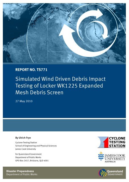
1 Department <strong>of</strong> Public Works | James Cook UniversityREPORT NO. TS771<strong>Simulated</strong> <strong>Wind</strong> <strong>Driven</strong> <strong>Debris</strong> <strong>Impact</strong><strong>Testing</strong> <strong>of</strong> <strong>Locker</strong> <strong>WK1225</strong> ExpandedMesh <strong>Debris</strong> Screen27 May 2010By Ulrich FryeCyclone <strong>Testing</strong> StationSchool <strong>of</strong> Engineering and Physical SciencesJames Cook Universityfor Queensland GovernmentDepartment <strong>of</strong> Public WorksGPO Box 2457, Brisbane, QLD 4001Disaster PreparednessDepartment <strong>of</strong> Public Works
2 Department <strong>of</strong> Public Works | James Cook University1 IntroductionIn this testing program, simulated wind driven debris impact loading <strong>of</strong> a debris screen to be installedon public cyclone shelters in Queensland was performed. The screen was loaded in accordance with theDesign Guidelines for Queensland Public Cyclone Shelters, Sep 2006. The testing was performed with theuse <strong>of</strong> new test materials, purchased from the manufacturer. All tests were conducted in the air cannontesting facility located at James Cook University.2 Design Guidelines for <strong>Debris</strong> LoadsThe structural design guidelines for debris loads state that the external fabric <strong>of</strong> public cyclone shelters isto be at least capable <strong>of</strong> resisting wind debris defined as:a) Five spherical steel balls <strong>of</strong> 2 grams mass and 8 mm diameter impacting at 0.4 x V 10,000 forhorizontal trajectories and 0.3 x V 10,000 for vertical trajectories.b) A 100 mm x 50 mm piece <strong>of</strong> timber <strong>of</strong> 4 kg mass impacting end-on at 0.4 x V 10,000 for horizontaltrajectories and 0.1 x V 10,000 for vertical trajectories.In Queensland’s tropical cyclone region (Region C) V 10,000 = 85 m/s. Thus, the required impact speeds are:0.1 x V 10,000 = 8.5 m/s0.3 x V 10,000 = 25.5 m/s0.4 x V 10,000 = 34.0 m/s3 Test Criteria and Procedures3.1 Test LoadsFor Cyclonic Regions C the debris test loads for the external fabric <strong>of</strong> public cyclone shelters are specifiedas follows:• Test Load A: End-on impact <strong>of</strong> timber 4 kg in mass, with cross-section dimensions <strong>of</strong> 100 mm x 50 mm,impacting at the speed specified for the trajectory.• Test Load B: Series <strong>of</strong> five steel balls <strong>of</strong> 2 grams mass and 8 mm diameter, successively impacting at thespeed specified for the trajectory.3.2 Test SequenceA test specimen shall be subject to successive test loads applied in the following order:1) <strong>Debris</strong> Test Load A2) <strong>Debris</strong> Test Load BTest load A shall impact the most critical location(s). The testing authority shall determine the most criticallocation(s) by test. Test load B shall successively impact at various random locations on the test specimen.3.3 Acceptance CriteriaA test specimen shall:a) Prevent a debris missile from penetrating throughb) In the case <strong>of</strong> a debris screen,1) If perforated, have a maximum perforation area <strong>of</strong> less than 2,000 mm 22) Not deflect more than 0.8 times the clear distance between the screen and the glazing, at anystage <strong>of</strong> the test.
3 Department <strong>of</strong> Public Works | James Cook University4 Test Apparatus and ProcedureThe screen test specimen was tested in the Cyclone <strong>Testing</strong> Station’s air cannon testing facility; the aircannon was used to fire the timber missile. The air cannon consists <strong>of</strong> a cylinder, which is pressurisedby an air compressor. Once the required air pressure is reached a solenoid valve is triggered toinstantaneously release the air and the missile is fired through the barrel and accelerates to the requiredvelocity.The test specimens were mounted on a target support frame located about 2200 mm away from the exitopening <strong>of</strong> the barrel. A digital velocity meter is installed at the exit <strong>of</strong> the barrel to measure the velocity<strong>of</strong> the missile, at its tail end, before they impacted the target.5 Test SpecimensThe debris screen system tested in this program consisted <strong>of</strong> a support frame and the mesh materialcovering the clear opening.5.1 FrameThe debris screen frame was made from 50 x 50 x 3 mm SHS steel. The frame had overall dimensions<strong>of</strong> 1600 mm width and 2000 mm height; at mid height was a cross SHS section, effectively splitting theopen mesh area into two equal sections <strong>of</strong> 1500 mm width and 925 mm height. Six fixing brackets werewelded to the rear <strong>of</strong> the SHS frame at locations shown in Figure 1 (FB); the brackets were made from100 x 75 x 6 mm steel angle, cut to 100 mm length, with 16 mm holes for wall mounting. Figure 1 showsa drawing <strong>of</strong> the frame layout including impact locations. Note that only one half <strong>of</strong> the frame was fittedwith mesh.Figure 1: Drawing <strong>of</strong> debris screen frame showing dimensions, fixing bracket and impact locations5.2 <strong>Locker</strong> <strong>WK1225</strong> Expanded MeshThe <strong>Locker</strong> <strong>WK1225</strong> mesh infill is a raised expanded G300 steel mesh with thickness <strong>of</strong> 2.5 mm andstrand width <strong>of</strong> 4.7 mm. The diamond shaped openings are <strong>of</strong> dimensions 5 x 16 mm.
4 Department <strong>of</strong> Public Works | James Cook University5.3 Screen AssemblyThe mesh was face mounted onto the support frame. Around the perimeter and the cross member a50 x 50 x 20 angle section was used to clamp the mesh to the frame; the angle was screw fixed to theframe (through the mesh) with 14-20 x 45 mm self-drilling metal screws at 300 mm centres.6 ResultsA summary <strong>of</strong> the test results is presented in Table 1. Further details on the modes <strong>of</strong> failure anddeformation are provided in Appendix A.Table 1: <strong>Impact</strong> <strong>Testing</strong> ResultsTrialNo.DateTested<strong>Impact</strong>LocationTestLoad<strong>Impact</strong>Velocity(m/s)ScreenDeflection(mm)Results and Observations1 17 Oct2008Corner <strong>of</strong> mesh A 33.8 NotmeasuredPass. Mesh strands fractured.Perforation area less than 2,000 mm 22 13 Nov2008Centre <strong>of</strong> mesh A 34.1 200 Pass. 5 mesh strands fractured.3 18 Nov2008Various(5 impacts)B ~34.0 NotmeasuredPass. Small indentations.Note: All impacts were performed on the same specimen7 ConclusionsA test program <strong>of</strong> simulated wind driven debris impact loading was performed on a <strong>Locker</strong> <strong>WK1225</strong>expanded mesh debris screen system.The methods and criteria <strong>of</strong> testing (in accordance with the Design Guidelines for Queensland PublicCyclone Shelters, Sep 2006 including amendment 1) have been presented. The results demonstrate theperformance <strong>of</strong> the screen when subjected to <strong>Debris</strong> Test Loads A and B.The debris screen system tested is deemed to satisfy the impact load performance requirements detailedin the Design Guidelines for Queensland Public Cyclone Shelters, Sep 2006.Prepared byCheckedMr. U. Frye Mr. C. J. Leitch Pr<strong>of</strong> Y. HeResearch Engineer Manager Head <strong>of</strong> SchoolCyclone <strong>Testing</strong> Station Cyclone <strong>Testing</strong> Station School <strong>of</strong> Engineering and Physical SciencesJames Cook University James Cook University James Cook UniversityNote: This report may not be:• Published, except in full, unless permission for publication <strong>of</strong> an approved abstract has been obtained in writingfrom the Head, School <strong>of</strong> Engineering and Physical Sciences;• Or cited in any publication or advertising material, unless the proposed citation has been submitted to andapproved in writing by the Head, School <strong>of</strong> Engineering and Physical Sciences.
5 Department <strong>of</strong> Public Works | James Cook UniversityAppendix A – Photographs <strong>of</strong> Tested ScreenFigure 2: Front (left) and rear views <strong>of</strong> screen after Trial 1Figure 3: Front (left) and rear views <strong>of</strong> screen after Trial 2


