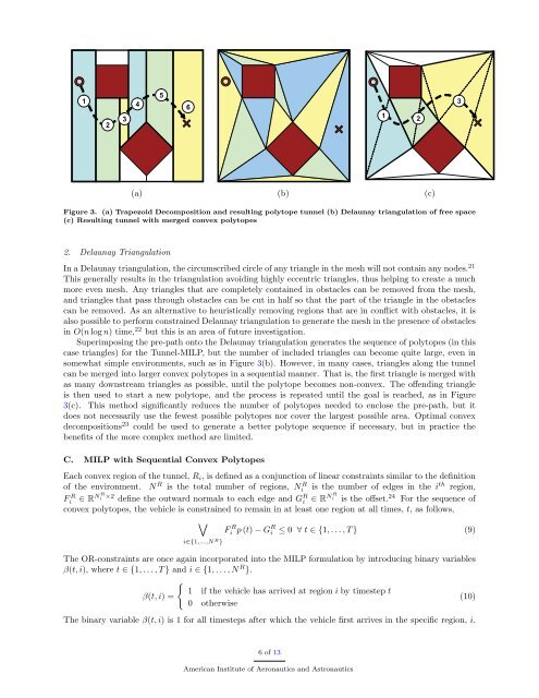
123456123123(a) (b) (c)Figure 3. (a) Trapezoid Decomposition and resulting polytope tunnel (b) Delaunay triangulation of free space(c) Resulting tunnel <strong>with</strong> merged convex polytopes2. Delaunay TriangulationIn a Delaunay triangulation, the circumscribed circle of any triangle in the mesh will not contain any nodes. 21This generally results in the triangulation avoiding highly eccentric triangles, thus helping to create a muchmore even mesh. Any triangles that are completely contained in obstacles can be removed from the mesh,and triangles that pass through obstacles can be cut in half so that the part of the triangle in the obstaclescan be removed. As an alternative to heuristically removing regions that are in conflict <strong>with</strong> obstacles, it isalso possible to perform constrained Delaunay triangulation to generate the mesh in the presence of obstaclesin O(n log n) time, 22 but this is an area of future investigation.Superimposing the pre-path onto the Delaunay triangulation generates the sequence of polytopes (in thiscase triangles) for the <strong>Tunnel</strong>-<strong>MILP</strong>, but the number of included triangles can become quite large, even insomewhat simple environments, such as in Figure 3(b). However, in many cases, triangles along the tunnelcan be merged into larger convex polytopes in a sequential manner. That is, the first triangle is merged <strong>with</strong>as many downstream triangles as possible, until the polytope becomes non-convex. The offending triangleis then used to start a new polytope, and the process is repeated until the goal is reached, as in Figure3(c). This method significantly reduces the number of polytopes needed to enclose the pre-path, but itdoes not necessarily use the fewest possible polytopes nor cover the largest possible area. Optimal convexdecompositions 23 could be used to generate a better polytope sequence if necessary, but in practice thebenefits of the more complex method are limited.C. <strong>MILP</strong> <strong>with</strong> <strong>Sequential</strong> <strong>Convex</strong> PolytopesEach convex region of the tunnel, R i , is defined as a conjunction of linear constraints similar to the definitionof the environment. N R is the total number of regions, Ni R is the number of edges in the i th region,Fi R ∈ R N R i ×2 define the outward normals to each edge and G R i ∈ R N R i is the offset. 24 For the sequence ofconvex polytopes, the vehicle is constrained to remain in at least one region at all times, t, as follows,∨Fi R p (t) − G R i ≤ 0 ∀ t ∈ {1, . . . , T } (9)i∈{1,...,N R }The OR-constraints are once again incorporated into the <strong>MILP</strong> formulation by introducing binary variablesβ(t, i), where t ∈ {1, . . . , T } and i ∈ {1, . . . , N R }.{1 if the vehicle has arrived at region i by timestep tβ(t, i) =(10)0 otherwiseThe binary variable β(t, i) is 1 for all timesteps after which the vehicle first arrives in the specific region, i.6 of 13American Institute of Aeronautics and Astronautics
Boundary conditions on the binary decision variable are set to require starting in the first region and endingin the final region by timestep T .β(t − 1, i) ≤ β(t, i) ∀t ∈ {2, . . . , T }, i ∈ {1, . . . , N R }β(t, 1) = 1 ∀t ∈ {1, . . . , T }β(T, i) = 1 ∀i ∈ {1, . . . , N R }Since the regions are sequenced together to form a tunnel through the environment, the following constraintenforces the sequential ordering of the polytopesβ(t, i + 1) ≤ β(t, i) ∀t ∈ {1, . . . , T }, i ∈ {1, . . . , N R − 1} (12)which states that the regions must be traversed in sequential order. From the binary constraints, the activeregion at timestep, t, can be found by taking the following difference of the binary variables,ρ(t, i) = β(t, i) − β(t, i + 1) ∀t ∈ {1, . . . , T }, i ∈ {1, . . . , N R − 1}ρ(t, N R ) = β(t, N R ) ∀t ∈ {1, . . . , T }where ρ(t, i) indicates whether region i is the active region at time t. A subtlety of the constraints inEquations (11) and (12) is that it allows regions to be skipped; this can be verified by observing that ifβ(t − 1, i) = β(t − 1, i + 1) = 0 and β(t, i) = β(t, i + 1) = 1, then Equations (11) and (12) are still satisfied,implying that no timestep exists for which the vehicle position lies <strong>with</strong>in region i.A method used to invalidate constraints when inactive is called the big-M formulation; 25 it uses a large,positive constant, M, to invalidate the constraint when a binary variable indicates it is inactive. UsingEquations (12) and (13) and the big-M formulation to invalidate the constraints when the vehicle is notinside the region, the vehicle can be constrained to sequentially go through the polytopes.F R i p(t) − G R i ≤ M (1 − ρ(t, i)) ∀t ∈ {1, . . . , T }, i ∈ {1, . . . , N R } (14)Finally, the overall <strong>MILP</strong> optimization problem <strong>with</strong> sequential convex polytopes formulation can be stated.<strong>Sequential</strong> convex polytope program(11)(13)minimize J(u, t f )subject to (1) if f(t) = 0(2), (3), (6)(11), (12), (14)(P3.1)The following section provides a brief analysis of the optimality of the solution for the <strong>Tunnel</strong>-<strong>MILP</strong>algorithm as well as the computational complexity.IV.Algorithmic AnalysisBy decomposing the obstacle avoidance problem into three stages, the <strong>Tunnel</strong>-<strong>MILP</strong> algorithm seeks togain performance improvements over the standard <strong>MILP</strong> methodology <strong>with</strong>out sacrificing too much in theway of optimality of the solution. Necessarily, the selection of a specific tunnel of polygons through whichto travel restricts the set of dynamically feasible solutions that can be achieved and may eliminate the trueoptimal solution as part of the first two stages of the algorithm. It is therefore no longer possible to guaranteeglobal optimality of the solution generated by the <strong>Tunnel</strong>-<strong>MILP</strong> algorithm. However, the path found in thethird phase of the algorithm is the optimal path that can be found <strong>with</strong>in the sequence of polygons selected.The likelihood of significant differences between the global optimal solution and the <strong>Tunnel</strong>-<strong>MILP</strong> solutiondepends directly on the ability of the vehicle to navigate sharp corners along the desired path generated inthe algorithms second stage. If, for example, the acceleration bounds are tight and the requirement to satisfyvehicle dynamics becomes quite restrictive, then a long arching route around a set of obstacles may proceedmuch more quickly than a slower route through tight passages in the environment. This issue is quantified7 of 13American Institute of Aeronautics and Astronautics