Download PDF
Download PDF
Download PDF
- No tags were found...

You also want an ePaper? Increase the reach of your titles
YUMPU automatically turns print PDFs into web optimized ePapers that Google loves.
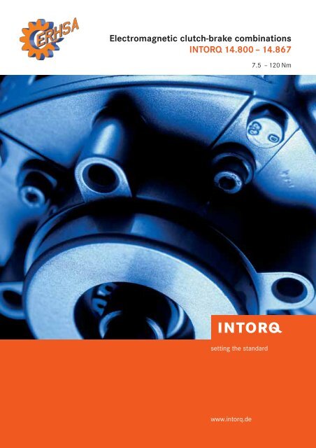
Electromagnetic clutch-brake combinationsINTORQ 14.800 – 14.8677.5 – 120 Nmsetting the standardwww.intorq.de
INTORQ I Clutch-brake combinations I en 5/2007ContentsClutch-brake combinationsProduct information 4Type code 6Design selection 8Overview of types 9Dimensioning 12Selection table 16Shaft loads 17Dimensions 18Clutch-brake combinations withhelical and worm gearboxesProduct information 30Type code 31Overview of types 32Permissible radial and axial forcesDrive 33Shaft loads 35Selection tables 36Dimensions 38Designs andterminal box positions 46Clutch-brake combinations,single elements withouthousingProduct information 48Type code 48Technical data 48Dimensions 49AccessoriesElectronic dual switch 50Spark suppressor 53High-speed switchgear 54Sales and servicearound the world 563
INTORQ I Clutch-brake combinations I en 5/2007Clutch-brake combinationsProduct informationElectromagnetic clutch-brake combinations have beenenjoying market success for a number of years. They areused in all areas of mechanical engineering when aproduction sequence has to be synchronised. As the driveruns continuously with the clutch rotor, the energy from theupstream drive can be used to accelerate the output.INTORQ 14.105/115 series electromagnetic clutches andbrakes are used in these clutch-brake combinations. Theyare switched alternately in order to accelerate or deceleratethe output shaft. Torque transmission is achieved usingfriction.As well as the basic versions with free drive and outputshafts and hollow shafts, clutch-brake combinations arealso available with built-on three-phase AC motors and withhelical or worm gearboxes mounted at the output end. Thedrives can be used in either a horizontal or vertical mountingposition. Using preassembled units significantly reducesdesign costs for new developments and the time spent onmounting.Friction clutches and brakes are subject to a certain amountof wear which is dependent on the switching energy used.Automatic adjusting devices (which are susceptible to faults)are no longer required, thanks to the wear resistant,asbestos-free friction linings used.Air gap compensation can be carried out quickly andwithout disassembling the clutch-brake combination thanksto patented wear adjustment. The low moments of inertia ofthe wear-resistant armature plates permit high switchingfrequencies and good positioning accuracy which can beincreased still further if required, using the high-speedswitchgear that is available.Features| Five frame sizes from 7.5 – 120 Nm| Asbestos-free friction lining| Patented air gap adjustment can be performed externallywithout disassembling the combination.| Operating times of the clutch and brake do not overlap.| A backlash-free version can be supplied on request.| Two shaft and two hollow shaft diameters as well as twoflange diameters in IEC dimensions are available for eachsize.| Two axis heights are available for each size.| Insulation material class B| Dimensioned for 100% duty| IP44 degree of protection, higher degrees on request| Rated voltage 24 V DC, other voltages on request| Variable terminal box position; standard position is on leftwhen looking at the drive end.| VDE 0580Armature plateRotorBrake stators lüClutch statorOutputDrive4
INTORQ I Clutch-brake combinations I en 5/2007Clutch-brake combinationsProduct informationPatented adjusting deviceINTORQ 14.800 – 867Fig. 1 Fig. 2Output cover with adjusting device and splined armature plate (Fig. 1)Output cover with adjusting device and backlash-free diaphragm armature plate (Fig. 2)The same air gap adjusting device is provided for eachoutput cover. The sequence of functions is described below.The description of the patented adjusting device applies toboth versions. If required, the air gap can be compensatedas follows:| Loosen the four screws (1) in the housing cover at theoutput end until the pressure on the compression springsbeneath it is relieved but do not remove them completely.| Remove the cover from the slot in the housing. Insert acylindrical pin into the bore which then becomes visible.This pin must be capable of radially twisting the ring (2).| Turn the ring in the direction of the arrow. When you feelresistance, turn it back by one scale marking (equal to therated air gap).After adjusting the air gap, retighten the screws (1) andinsert the cover into the housing.This simple way of adjusting an air gap can be also beperformed easily on built-in combinations.5
INTORQ I Clutch-brake combinations I en 5/2007Clutch-brake combinationsType codeINTORQ 14.800 – 14.810INTORQ 14.800. 06. 10. 1TypeSizeOutput-end versionDrive-end versionVariants6
INTORQ I Clutch-brake combinations I en 5/2007Clutch-brake combinationsType codeINTORQ 14.800 – 14.810TypeINTORQ 14.800 – clutch-brake combinationswithout motorINTORQ 14.810 –clutch-brake combinationswith motorOutput-end version10 – free output shaft, without foot, without flange11 – free output shaft, with foot, without flange12 – free output shaft, without foot, with flange13 – free output shaft, with foot, with flange20 – with hollow shaft, without foot, without flange21 – with hollow shaft, without foot, with flange22 – with hollow shaft, with foot, without flange23 – with hollow shaft, with foot, with flangeDrive-end version1 – splined armature plate, free drive shaft2 – splined armature plate, free drive shaft and flange3 – splined armature plate, hollow shaft, B5 flange4 – splined armature plate, hollow shaft, B14 flange6 –backlash-free diaphragm armature plate,free drive shaft7 –backlash-free diaphragm armature plate,free drive shaft and flange8 –backlash-free diaphragm armature plate, hollow shaft,B5 flange9 –backlash-free diaphragm armature plate, hollow shaft,B14 flangeVariantsClutch/brake voltageShaft diameter/bore diameter/flange diameter/footheight/terminal box positionMotor:Power – voltageSpeed – frequencyDegree of protectionFor available motor frame sizes, see page 11.7
INTORQ I Clutch-brake combinations I en 5/2007Clutch-brake combinationsDesign selectionINTORQ 14.800Versionswith splined armature plateVersions withbacklash-free diaphragm armature plateVersion 10.1 10.2 10.3 10.4 10.6 10.7 10.8 10.9Drive Free shaft Free shaft and Hollow shaft and Hollow shaft and As As As AsB5 flange B5 flange B14 flangeOutput Free shaft Free shaft Free shaft Free shaft 10.1 10.2 10.3 10.4Foot mounting – – – –Version 11.1 11.2 – 11.4 11.6 11.7 – 11.9Drive Free shaft Free shaft Hollow shaft and As As – Asand B5 flange – B14 flangeOutput Free shaft Free shaft – Free shaft 11.1 11.2 – 11.4Foot mounting With feet With feet – With feetVersion 12.1 12.2 12.3 12.4 12.6 12.7 12.8 12.9Drive Free shaft Free shaft Hollow shaft Hollow shaft and As As As Asand B5 flange and B5 flange B14 flangeOutput Free shaft Free shaft Free shaft Free shaft andand B5 flange and B5 flange and B5 flange B5 flange 12.1 12.2 12.3 12.4Foot mounting – – – –Version 13.1 13.2 – 13.4 13.6 13.7 – 13.9Drive Free shaft Free shaft Hollow shaft and As As – Asand B5 flange – B14 flangeOutput Free shaft Free shaft Free shaftand B5 flange and B5 flange – and B5 flange 13.1 13.2 – 13.4Foot mounting With feet With feet – With feetVersion 20.1 20.2 20.3 20.4 20.6 20.7 20.8 20.9Drive Free shaft Free shaft Hollow shaft Hollow shaft As As As Asand B5 flange and B5 flange and B14 flangeOutput Hollow shaft Hollow shaft Hollow shaft Hollow shaft 20.1 20.2 20.3 20.4Foot mounting – – – –Version 21.1 21.2 21.3 21.4 21.6 21.7 21.8 21.9Drive Free shaft Free shaft Hollow shaft Hollow shaft As As As Asand B5 flange and B5 flange and B14 flangeOutput Hollow shaft Hollow shaft Hollow shaft Hollow shaftand B5 flange and B5 flange and B5 flange and B14 flange 21.1 21.2 21.3 21.4Foot mounting – – – –Version 22.1 22.2 – 22.4 22.6 22.7 – 22.9Drive Free shaft Free shaft Hollow shaft As As – Asand B5 flange – and B14 flangeOutput Hollow shaft Hollow shaft – Hollow shaft 22.1 22.2 – 22.4Foot mounting With feet With feet – With feetVersion 23.1 23.2 – 23.4 23.6 23.7 – 23.9Drive Free shaft Free shaft Hollow shaft As As – Asand B5 flange – and B14 flangeOutput Hollow shaft Hollow shaft Hollow shaftand B5 flange and B5 flange – and B5 flange 23.1 23.2 – 23.4Foot mounting With feet With feet – With feet8
INTORQ I Clutch-brake combinations I en 5/2007Clutch-brake combinationsOverview of typesOutputDrive OutputDrive◊ ◊ ◊ ◊Output◊Drive◊INTORQ 14.800.òò.10.1(6) Page 18INTORQ 14.800.òò.10.2(7) Page 18INTORQ 14.800.òò.10.3(8) Page 20Output◊Drive◊Output◊Drive◊Output◊Drive◊INTORQ 14.800.òò.10.4(9) Page 22INTORQ 14.800.òò.11.1(6) Page 18INTORQ 14.800.òò.11.2(7) Page 18Output◊Drive◊Output◊Drive◊Output◊Drive◊INTORQ 14.800.òò.11.4(9) Page 22INTORQ 14.800.òò.12.1(6) Page 18INTORQ 14.800.òò.12.2(7) Page 18Output◊Drive◊Output◊Drive◊Output◊Drive◊INTORQ 14.800.òò.12.3(8) Page 20INTORQ 14.800.òò.12.4(9) Page 22INTORQ 14.800.òò.13.1(6) Page 18Output◊Drive◊Output◊Drive◊Output◊Drive◊INTORQ 14.800.òò.13.2(7) Page 18INTORQ 14.800.òò.13.4(9) Page 22INTORQ 14.800.òò.20.1(6) Page 24Output◊Drive◊Output◊Drive◊Output◊Drive◊INTORQ 14.800.òò.20.2(7) Page 24INTORQ 14.800.òò.20.3(8) Page 26INTORQ 14.800.òò.20.4(9) Page 289
INTORQ I Clutch-brake combinations I en 5/2007Clutch-brake combinationsOverview of typesOutputDriveOutputDrive◊ ◊ ◊ ◊Output◊Drive◊INTORQ 14.800.òò.21.1(6) Page 24INTORQ 14.800.òò.21.2(7) Page 24INTORQ 14.800.òò.21.3(8) Page 26Output◊Drive◊Output◊Drive◊Output◊Drive◊INTORQ 14.800.òò.21.4(9) Page 28INTORQ 14.800.òò.22.1(6) Page 24INTORQ 14.800.òò.22.2(7) Page 24Output◊Drive◊Output◊Drive◊Output◊Drive◊INTORQ 14.800.òò.22.4(9) Page 28INTORQ 14.800.òò.23.1(6) Page 24INTORQ 14.800.òò.23.2(7) Page 24Output◊Drive◊INTORQ 14.800.òò.23.4(9) Page 28Output◊Drive◊Output◊Drive◊Output◊Drive◊INTORQ 14.810.òò.10.3(8) Page 20INTORQ 14.810.òò.10.4(9) Page 22INTORQ 14.810.òò.11.4(9) Page 22Output◊Drive◊Output◊Drive◊Output◊Drive◊INTORQ 14.810.òò.12.3(8) Page 20INTORQ 14.810.òò.12.4(9) Page 22INTORQ 14.810.òò.13.4(9) Page 2210
INTORQ I Clutch-brake combinations I en 5/2007Clutch-brake combinationsOverview of typesOutputDriveOutputDrive◊ ◊ ◊ ◊Output◊Drive◊INTORQ 14.810.òò.20.3(8) Page 26INTORQ 14.810.òò.20.4(9) Page 28INTORQ 14.810.òò.21.3(8) Page 26Output◊Drive◊Output◊Drive◊Output◊Drive◊INTORQ 14.810.òò.21.4(9) Page 28INTORQ 14.810.òò.22.4(9) Page 28INTORQ 14.810.òò.23.4(9) Page 28The INTORQ 14.810 is supplied complete with a built-onthree-phase AC motor but it is not shown in separatedimension drawings. The dimensions of this clutch-brakecombination can be found in the 14.800 dimension tables.For example, the dimensions for the 14.810.06.12.4 versionshould be taken from the 14.800.06.12.4 dimension tableon pages 22/23.The assignment of the available motor frame sizes anddesigns can be seen in the table below.INTORQ Size Motor mounting Flange14.810.06.òò.3(8) 71 B5 16014.810.06.òò.4(9) 71 B14 C10514.810.08.òò.3(8) 80 B5 20014.810.08.òò.4(9) 80 B14 C12014.810.10.òò.3(8) 90 B5 20014.810.10.òò.4(9) 90 B14 C14014.810.12.òò.3(8) 100 B5 25014.810.12.òò.4(9) 100 B14 C16014.810.16.òò.3(8) 132 B5 30014.810.16.òò.4(9) 132 B14 C20011
INTORQ I Clutch-brake combinations I en 5/2007Clutch-brake combinationsDimensioningSelecting the sizeDimensioning is carried out in accordance with VDIGuideline 2241.Symbols used in calculations:M K Rated torque of the clutch or brake in NmM load Load torque in NmM a Acceleration or deceleration torque in NmM req Required torque in NmP Drive power in kW∆ no Initial relative speed of the clutch or brake in rpmJ load Moment of inertia of all output components referredto the clutch shaft in kgm 2t 3 Slipping time in seconds during which there is arelative movement between the drive and output ifthe clutch or brake is closedt 11 Engagement delay time in seconds, i.e. the time fromswitching the voltage on to experiencing an increasein torquet 12 Torque rise time in seconds, i.e. the time from thestart of the torque increase until rated torque M K isreachedt 1 Engagement time in seconds, i.e. the sum of t 11 + t 12t 2 Disengagement time in seconds, i.e. the time fromswitch-off until 10% of rated torque MK is reachedK Safety factor 2Q Calculated switching energy per switching cycle in JQ E Max. permissible switching energy for one switchingoperation in J, in accordance with the table on page18Q perm Max. permissible switching energy in JS h Operating frequency per hour, i.e. the number ofworking cycles distributed evenly over the timeperiodZ NA Number of switching operations until readjustmentThe required size is dimensioned essentially in accordancewith the required torques or braking torques. The inertias tobe accelerated or braked (moments of inertia), the relativespeeds, the acceleration or deceleration times, the requiredoperating frequencies and the desired service life should allbe included in the calculation. The ambient conditions forthe site of use of housed clutches should be known. Suchconditions could include, for example, extraordinaryambient temperatures, extremely high air humidity and dustaccumulation.Friction surfaces must always be kept free of oil andgrease.12
INTORQ I Clutch-brake combinations I en 5/2007Clutch-brake combinationsDimensioningSafety factorIn order to achieve the required transmission security evenin extreme operating conditions, the calculated torque ismultiplied by safety factor K. The value of K is determined bythe operating conditions. K 2Load typesIn practice, the following load types mainly occur:| Purely dynamic loadA purely dynamic load is present when flywheels, rolls orsimilar are to be accelerated or decelerated andthe static load torque is negligible.M req = M a · K M KM a =J load · ∆n 09.55 · $t 3 - t 122 %M req =J load · ∆n 09.55 · $t 3 - t 122 %· K| Dynamic and static loadThe majority of applications belong to this mixed category,as a dynamic load is present in addition to a static loadtorque in most cases.M req = (M a M load ) · K M KThe required size is usually calculated using the clutch oracceleration process.M reqT=IJ load · ∆n 0 Mload · K9.55 · $t 3 - t 122 %+M load = to engage clutch and accelerate load–M load = to engage brake and decelerate loadEstimated required torque or sizeIf only the drive power to be transmitted is known, therequired torque or braking torque can be determined asfollows:Acceleration and delay timeIf the rated torque is specified and the moment of inertiaand load torque are both known, the acceleration or delaytime can be determined as follows:M req = 9550 P · K MK nt 3 =Jload · ∆n 0 t 129.55 · (M K M load ) 2–M load = to engage clutch and accelerate load+M load = to engage brake and decelerate load13
INTORQ I Clutch-brake combinations I en 5/2007Clutch-brake combinationsDimensioningThermal loadWhen dimensioning clutches and brakes, other importantfactors to be taken into account are the switching energyper switching cycle and the operating frequency. Theavailable switching energy per switching cycle (engaging theclutch and braking) is calculated using the formula below:Q = J load ·∆n 02 .182.5The permissible friction energy per switching cycle at agiven operating frequency can be taken from the diagram onpage 16. If the friction energy per switching cycle is known,the permissible operating frequency can also be taken fromthe diagram.M$K M K %M K M loadM K M loadExampleThe following technical data is known for a packagingmachine's positioning mode:J load = 0.01 kgm 2 totalM load = 6 Nm∆n o = 700 rpmt 3 = 0.15 sS h = 4000 switching operations per hourJM a = load · ∆n 2 0 0.01 · 7009.55 · t 3 – t =12 9.55 · (0.15 – 0.03)2$ %t 12 assumed as 0.03 s2M a = 6.1 Nm M req = (M a M load ) · K = (6.1 6) · 2 M req = 24.2 NmSelected clutch-brake combination:INTORQ 14.800.10.11.1With MK = 30 NmCalculation of the available switching energy per switchingcycle:M K M K0.01 · 7002Q = ·182.5 M K M load M K M load182.5Q = J load ·∆n 02 .$ %$ %30 3030 6 30 6Q = 55.9 JSee the diagram (page 16) for S perm depending on thecalculated switching energy.The required operating frequency is permissible at thecalculated switching energy for the selected size (10).Ordering exampleINTORQ 14.800.10.11.124 V DC, shaft Ø 19 mm/19 mm14
INTORQ I Clutch-brake combinations I en 5/2007Clutch-brake combinationsDimensioningOperating timesThe operating times listed in the tables apply to switching onthe DC side with a rated air gap and warm coil.These are mean values whose variation depends on,amongst other things, the rectification type and the air gapS lü .Time concepts when engaging anddisengagingExcitation Excitation Rated torquet 2t 11 t 12t 2tt 1OnClutch0.1 M KOffOn0.1 M K11BrakeOffTime tTime tt 11 = Engagement delay timet 12 = Rise time of torquet 1 = Engagement timet2 = Disengagement time:t 2 brake ;t 11 clutcht 2 clutch ;Pt 11 brakeTime tOperating times in millisecondsSize INTORQ 14.800/810/852 to 867 and 14.137/138E clutchE braket 11 ≈ t 2 t 12 t 1 t 12 t 106 20 35 55 25 4508 25 70 95 30 5510 35 85 120 50 8512 50 120 170 75 12516 65 145 210 85 15015
INTORQ I Clutch-brake combinations I en 5/2007Clutch-brake combinationsSelection tableINTORQ M 1) K P20 2) n max Q E Moments of inertia14.800 – 867 Nm W rpm J J x 10 -5 , kgm 2Armature plate Size 14.105 Clutch Brake Rotor Armature Outputversion 14.115 plate shaft06 7.5 15 11.5 3000 3.6 x 10 3 11.9 4.2 0.7With 08 15 20 16 3000 6 x 10 3 26.6 13.9 2.4splinedarmature plate10 30 28 21 3000 10 x 10 3 78 41.4 6.512 60 35 28 3000 16 x 10 3 226 120 15.816 120 50 38 3000 25 x 10 3 630 378 6406 7.5 15 11.5 3000 3.6 x 10 3 11.9 6.5 1.2With08 15 20 16 3000 6 x 10 3 26.6 25.3 3.7backlash-freediaphragm10 30 28 21 3000 10 x 10 3 78 82.1 10.2armature 12 60 35 28 3000 16 x 10 3 226 241 23.3plate16 120 50 38 3000 25 x 10 3 630 800 85| Standard voltage 24 V DC| 1) M K , in relation to n = 100 rpm| 2) At 20°CINTORQ 14.800/810/852 ÷ 867 and 14.137/138SizesPermissible switching energy Qperm [J]Operating frequency S h [h -1 ]16
INTORQ I Clutch-brake combinations I en 5/2007Clutch-brake combinationsShaft loadsThe radial forces specified in the table relate to the centre ofthe shaft ends. F rmax is the maximum permissible radialforce in relation to the shaft strength.Force F rated underlies a bearing service life ofL h = 10,000 hours at n = 1500 rpm.These values can be converted to other service lives andspeeds with the aid of the diagram. However, you shouldensure that force Frmax is not exceeded. If additional axialforces are present, please inform us of them so that we canperform a recalculation.INTORQ 14.800 INTORQ 14.810F r max.F r max.F r max.Size Force ForceF rmax [N]F rated [N]06 600 32508 900 42510 1300 59012 1900 87016 2300 1350Correction factor3.02.52.01.51.0F= F rated · k F rmax0.5500 1000 1500 2000 2500 3000Speed n [rpm]L h =2000L h =5000L h =10,000L h =20,000F Permissible radial force in NF rmax Max. permissible radial force in N,in relation to shaft strengthF rated Permissible radial force in N for L h = 10,000 hand n = 1500 rpmk Correction factor from diagramExample:Size 08Speed n = 500 rpmService life L h = 5000 hoursF = 425 · 1.8 = 765 N < F rmax = 900 N17
INTORQ I Clutch-brake combinations I en 5/2007Clutch-brake combinationsDimensionsFree drive and output shaftsKeys to DIN 6885/1Centring to DR DIN 332OutputDriveINTORQ 14.800.òò.11.1(6) basic versionSize Clutch Brake b 1 e 1 d 1 f 1 g 1 g 2 h i 1 k 1 l 1 s 1 mM K P 20 P 20 h8 k6 kgNm W W06 7.5 15 11.5 52 6708 15 20 16 65 9010 30 28 21 78 11512 60 35 28 78 11516 120 50 38 98 14511 63 35 183 231410 90 8971 42 197 3014 71 42 230 301910 112 9580 52 250 4019 80 62 280 402419 140 11090 72 300 5024 100 72 324 502820 167 136112 82 344 6028 112 82 380 603820 210 158132 102 420 80M6 3M8 4.5M10 8M10 13M12 25FeetFlangeSize a b b 3 c e f i s mkgSize a 2 b 2 c 1 c 2 e 2 f 2 s 2 mj7kg06 100 80 85 3 115 10041.548.57 0.206140 9512 10115 390.4160 110 130 3.5 0.508 120 105 110 3 140 13055659 0.308160 11012 91303.59 0.5200 130 165 11.5 0.710 140 130 140 4 165 16070809 0.410200 13022 15165 3.5 11 0.8250 180 215 4 13.5 1.112 160 150 160 5 184 180829211 0.712200 13022 15165 3.5 11 0.8250 180 215 4 13.5 1.116 185 185 195 6 215 22397.5117.513 1.216250 18022 152154 13.51.3300 230 265 2.018
INTORQ I Clutch-brake combinations I en 5/2007Clutch-brake combinationsDimensionsFree drive and output shaftsM16x1.5INTORQ Feet Drive B5 flange Output B5 flange14.800.òò.10.1[6] – – –14.800.òò.10.2[7] – ö –14.800.òò.11.1[6] ö – –14.800.òò.11.2[7] ö ö –14.800.òò.12.1[6] – – ö14.800.òò.12.2[7] – ö ö14.800.òò.13.1[6] ö – ö14.800.òò.13.2[7] ö ö öOrder dataGeneral –If required –Type designation with specification of sizeand rated voltageDiameters of drive and output shaftsDiameters of drive and output flangesFoot heightBacklash-free diaphragm armature plate[value in brackets in the type designation]19
INTORQ I Clutch-brake combinations I en 5/2007Clutch-brake combinationsDimensionsDrive, hollow shaft, B5 flange –output, free shaftKeys to DIN 6885/1Keyways to DIN 6885/1JS9Centring to DR DIN 332OutputDriveINTORQ 14.800.òò.10.3[8] basic versionSize Clutch BrakeM K P 20 P 20 a 3 b 1 b 3 c 3 d 1 d 3 e 1 e 3 f 1 f 3 g 1 g 2 i 1 k 3 l 1 l 3 s 1 s 3 mNm W W h8 H9 k6 G7 kg06 7.5 15 11.508 15 20 1610 30 28 2112 60 35 28140 95.2 11 11 115 35 146 23 M8160 52 110.2 10 14 146713010 4 90 8942 153 3040 M69160 110.2 14 14 130 42 184 30 M8200 65 130.2 14 19 199016510 4 112 9552 194 4050 M811.5200 130.2 19 19 165 4 62 217 40 M10250 78 180.2 13 24 24115 215195140 110 72 227 5060 M1013.5200 130.2 24 24 165 4 72 251 50 M10250 78 180.2 16 28 28115 215205167 136 82 261 6070 M10M122.54.57.51216 120 50 38250 180.2 28 28 215 82 294 60300 98 230.2 20 38 38145 26520 5 210 158 102 314 8080 M12 M12 22Output flangeSize a 2 b 2 c 1 c 2 e 2 f 2 s 2 mj7kg0608101216140 9512 10115 390.4160 110 130 3.5 0.5160 11012 91303.59 0.5200 130 165 11.5 0.7200 13022 15165 3.5 11 0.8250 180 215 4 13.5 1.1200 13022 15165 3.5 11 0.8250 180 215 4 13.5 1.1250 18022 152154 13.51.3300 230 265 2.020
INTORQ I Clutch-brake combinations I en 5/2007Clutch-brake combinationsDimensionsDrive, hollow shaft, B5 flange –output, free shaftM16x1.5INTORQ Drive B5 flange Output B5 flange14.800.òò.10.3[8] ö –14.800.òò.12.3[8] ö öOrder dataGeneral –If required –Type designation with specification of sizeand rated voltageDiameter of drive hollow shaftDiameter of drive flangeDiameter of output shaftDiameter of output flangeBacklash-free diaphragm armature plate[value in brackets in the type designation]21
INTORQ I Clutch-brake combinations I en 5/2007Clutch-brake combinationsDimensionsDrive, hollow shaft,B14 flange –output, free shaftSize 06, 08, 10Keys to DIN 6885/1Keyways to DIN 6885/1JS9Centring to DR DIN 332OutputDriveINTORQ 14.800.òò.11.4[9] basic versionSize Clutch BrakeM K P 20 P 20 a 4 b 1 b 4 c 4 d 1 d 4 e 1 e 4 f 1 f 4 g 1 g 2 h i 1 k 4 l 1 l 4 s 1 s 4 mNm W W h8 H9 k6 G7 kg06 7.5 15 11.5 105 52 70.2 5.508 15 20 16 120 65 80.2 710 30 28 21 140 78 95.2 812 60 35 28 160 78 110.2 816 120 50 38 200 98 130.2 1011 11 63 35 152 2314 1467 85 10 3 90 8971 42 159 3014 14 71 42 186 3019 1990 100 10 4 112 9580 52 196 4019 19 80 62 225 4024 24115 115 19 4 140 11090 72 235 5024 24 100 72 261 5028 28115 130 20 4 167 136112 82 271 6028 28 112 82 309 60145 165 20 5 210 15838 38132 102 329 8050 M6 7 358 M8 7 4.570 M10 9 880 M10 9 1397 M12 12 24FeetOutput flangeSize a b b 3 c e f i s mkgSize a 2 b 2 c 1 c 2 e 2 f 2 s 2 mj7kg06 100 80 85 3 115 10041.548.57 0.206140 9512 10115 390.4160 110 130 3.5 0.508 120 105 110 3 140 13055659 0.308160 11012 91303.59 0.5200 130 165 11.5 0.710 140 130 140 4 165 16070809 0.410200 13022 15165 3.5 11 0.8250 180 215 4 13.5 1.112 160 150 160 5 184 180829211 0.712200 13022 15165 3.5 11 0.8250 180 215 4 13.5 1.116 185 185 195 6 215 22397.5117.513 1.216250 18022 152154 13.51.3300 230 265 2.022
INTORQ I Clutch-brake combinations I en 5/2007Clutch-brake combinationsDimensionsDrive, hollow shaft, B14 flange –output, free shaftM16x1.5INTORQ Feet Output B5 flange14.800.òò.10.4[9] – –14.800.òò.11.4[9] ö –14.800.òò.12.4[9] – ö14.800.òò.13.4[9] ö öOrder dataGeneral –If required –Type designation with specification of sizeand rated voltageDiameter of drive hollow shaftDiameter of output shaftDiameter of output flangeFoot heightBacklash-free diaphragm armature plate[value in brackets in the type designation]23
INTORQ I Clutch-brake combinations I en 5/2007Clutch-brake combinationsDimensionsDrive, free shaft – output, hollow shaftKeys to DIN 6885/1Keyways to DIN 6885/1JS9Centring to DR DIN 332OutputDriveINTORQ 14.800.òò.22.1[6] basic versionSize Clutch BrakeM K P 20 P 20 b 1 b 5 d 1 d 5 e 1 e 5 f 1 f 5 g 1 g 2 h i 1 i 5 k 1 l 1 l 5 s 1 s 5 mNm W W h8 h8 k6 G7 kg06 7.5 15 11.5 52 5208 15 20 16 65 6510 30 28 21 78 8612 60 35 28 78 9811 11 63 35 162 23 2314 1467 67 10 10 90 8971 4214169 30 3014 14 71 42 205 30 3019 1990 90 10 10 112 9580 5217216 40 4019 19 80 62 237 40 4024 24115 115 19 17 140 110 90 7217247 50 5024 24 100 72 273 50 5028 28115 115 20 20 167 136 112 8220283 60 60M6 M6 2.8M8 M8 4.5M10 M10 8M10 M10 1316 120 50 38 98 12028 28 112 82 324 60 6038 38145 145 20 21 210 158 132 10225.5 344 80 80M12 M12 25Feet Drive flange Output flangeSize a b b 3 c e f i i 6 s mkgSize a 2 b 2 c 1 c 2 e 2 f 2 s 2 mj7kgSize a 5 b 6 c 5 c 6 e 6 f 6 s 6 mH9kg41.506 100 80 85 3 115 100 48.520.5 7 0.206140 95 115 3 0.4160 110 12 10 9130 3.5 0.506140 95.2 115 0.4160 110.2 13 15 4 91300.55508 120 105 110 3 140 130 6530 9 0.308160 110 130 9 0.5200 130 12 9 165 3.5 11.5 0.708160 110.2 130 M8 0.5200 130.2 14 18 4165 11.5 0.77010 140 130 140 4 165 160 8027 9 0.410200 130 165 3.5 11 0.8250 180 22 15 215 4 13.5 1.110200 130.2 165 4 M10 0.8250 180.2 13 18 215 5 13.5 1.18212 160 150 160 5 184 180 9231 11 0.712200 130 165 3.5 11 0.8250 180 22 15 215 4 13.5 1.112200 130.2 165 4 M10 0.8250 180.2 16 21 215 5 M12 1.197.516 185 185 195 6 215 223 117.541.5 13 1.216250 180 215 1.3300 230 22 15 265 4 13.5 2.016250 180.2 215 1.3300 230.2 20 27 5 M122652.024
INTORQ I Clutch-brake combinations I en 5/2007Clutch-brake combinationsDimensionsDrive, free shaft – output, hollow shaftM16x1.5INTORQ Feet Drive B5 flange Output B5 flange14.800.òò.20.1[6] – – –14.800.òò.20.2[7] – ö –14.800.òò.21.1[6] – – ö14.800.òò.21.2[7] – ö ö14.800.òò.22.1[6] ö – –14.800.òò.22.2[7] ö ö –14.800.òò.23.1[6] ö – ö14.800.òò.23.2[7] ö ö öOrder dataGeneral –If required –Type designation with specification of sizeand rated voltageDiameters of drive shaft andoutput hollow shaftDiameters of drive and output flangesFoot heightBacklash-free diaphragm armature plate[value in brackets in the type designation]25
INTORQ I Clutch-brake combinations I en 5/2007Clutch-brake combinationsDimensionsDrive, hollow shaft, B5 flange – output, hollow shaftKeyways to DIN 6885/1JS9 Output DriveINTORQ 14.800.òò.20.3[8] basic versionSize Clutch BrakeM K P 20 P 20 a 3 b 3 b 5 c 3 d 3 d 5 e 3 e 5 f 3 f 5 g 1 g 2 i 5 k 3 l 3 l 5 s 3 s 5 mNm W W H9 h8 G7 G7 kg06 7.5 15 11.508 15 20 1610 30 28 2112 60 35 28140 95.2 11 11 115 23 M8160 110.2 52 10 14 14 130 67 5 10 90 89 14 125 40 30 10160 110.2 14 14 130 30 M8200 130.2 65 14 19 19 165 90 4 10 112 95 17 159 50 40 11.5200 130.2 19 19 165 4 40 M10250 180.2 86 13 24 24 215 115 517 140 110 17 174 6050 13.5200 130.2 24 24 165 4 50 M10250 180.2 98 16 28 28 215 115 20 167 136 20 201 70560 M12M6 2.5M8 4.5M10 7.5M10 1216 120 50 38250 180.2 28 28 215 60300 230.2 120 20 38 38 265 145 5 21 210 158 25.5 238 80 80M12 M12 22Output flangeSize a 5 b 6 c 5 c 6 e 6 f 6 s 6 mH9kg0608101216140 95.213 151154 90.4160 110.21300.5160 110.214 181304M8 0.5200 130.216511.5 0.7200 130.213 18165 4 M10 0.8250 180.2215 5 13.5 1.1200 130.216 21165 4 M10 0.8250 180.2215 5 M12 1.1250 180.220 272155 M121.3300 230.22652.026
INTORQ I Clutch-brake combinations I en 5/2007Clutch-brake combinationsDimensionsDrive, hollow shaft, B5 flange – output, hollow shaftM16x1.5INTORQ Drive B5 flange Output B5 flange14.800.òò.20.3[8] ö –14.800.òò.21.3[8] ö öOrder dataGeneral –If required –Type designation with specification of sizeand rated voltageDiameter of drive hollow shaftDiameter of drive flangeDiameter of output hollow shaftDiameter of output flangeBacklash-free diaphragm armature plate[value in brackets in the type designation]27
INTORQ I Clutch-brake combinations I en 5/2007Clutch-brake combinationsDimensionsDrive, hollow shaft, B14 flange – output, hollow shaftFrame size 06, 08, 10Keyways to DIN 6885/1JS9 Output DriveINTORQ 14.800.òò.22.4[9] basic versionSize Clutch BrakeM K P 20 P 20 a 4 b 4 b 5 c 4 d 4 d 5 e 4 e 5 f 4 f 5 g 1 g 2 h i 5 k 4 l 4 l 5 s 4 s 5 mNm W W H9 h8 G7 G7 kg11 11 63 2306 7.5 15 11.5 105 70.5 52 5.5 14 1485 67 3 10 90 897114 131 50307 M6 2.808 15 20 16 120 80.2 65 710 30 28 21 140 95.2 86 812 60 35 28 160 110.2 98 816 120 50 38 200 130.2 120 1014 14 71 3019 19100 90 4 10 112 958017 161 584019 19 80 4024 24115 115 4 17 140 110 9017 182 705024 24 100 5028 28130 115 4 20 167 136 11220 211 806028 28 112 6038 38165 145 5 21 210 158 13225.5 253 97807 M8 4.59 M10 89 M10 1312 M12 24FeetOutput flangeSize a b b 3 c e f i 6 s mkgSize a 5 b 6 c 5 c 6 e 6 f 6 s 6 mH9kg06 100 80 85 3 115 100 20.5 7 0.208 120 105 110 3 140 130 30 9 0.310 140 130 140 4 165 160 27 9 0.412 160 150 160 5 184 180 31 11 0.716 185 185 195 6 215 223 41.5 13 1.20608101216140 95.213 151154 90.4160 110.21300.5160 110.214 181304M8 0.5200 130.216511.5 0.7200 130.213 18165 4 M10 0.8250 180.2215 5 13.5 1.1200 130.216 21165 4 M10 0.8250 180.2215 5 M12 1.1250 180.220 272155 M121.3300 230.22652.028
INTORQ I Clutch-brake combinations I en 5/2007Clutch-brake combinationsDimensionsDrive, hollow shaft, B14 flange – output, hollow shaftM16x1.5INTORQ Feet Output B5 flange14.800.òò.20.4[9] – –14.800.òò.21.4[9] – ö14.800.òò.22.4[9] ö –14.800.òò.23.4[9] ö öOrder dataGeneral –If required –Type designation with specification of sizeand rated voltageDiameter of drive hollow shaftDiameter of output hollow shaftDiameter of output flangeFoot heightBacklash-free diaphragm armature plate[value in brackets in the type designation]29
INTORQ I Clutch-brake combinations I en 5/2007Clutch-brake combinationswith helical and helical-worm gearboxesProduct informationINTORQ 14.852/853/855/856/857INTORQ 14.852 INTORQ 14.855With this type series, a helical or worm gearbox is alreadydownstream of the clutch-brake combination with free driveshaft. In view of the frequent high switching frequencies, theconnection between the clutch-brake combination and thegearbox is backlash-free.Please refer to the selection tables below for possible outputspeeds and ratios. The drive can be connected to theseunits via flexible couplings and belt pulleys or sprockets.INTORQ 14.862/863/865/866/867INTORQ 14.862 INTORQ 14.865This type series is largely identical to the one describedabove. But these combinations are supplied with B14mounted three-phase AC motors instead of free drive shafts.The type of wear adjustment and the technical data areidentical to those for type series 14.800 and 810.30
INTORQ I Clutch-brake combinations I en 5/2007Clutch-brake combinationswith helical and helical-worm gearboxesType codeINTORQ 14.852 – 14.867 with Lenze helical gearboxesINTORQ 14.852. 06. GST/GSS 05. 1TypeSizeHelical gearbox/Helical-worm gearboxesGearbox sizeArmature plate versionVariantsTypeINTORQ 14.852 – free drive shaft and helical gearbox,B3 mountingINTORQ 14.853 – free drive shaft and helical gearbox,B5 mountingINTORQ 14.855 – free drive shaft and worm gearbox,B3 mountingINTORQ 14.856 – free drive shaft and worm gearbox,B5 mountingINTORQ 14.857 – free drive shaft and worm gearbox withhollow shaftINTORQ 14.862 – B14 motor and helical gearbox,B3 mountingINTORQ 14.863 – B14 motor and helical gearbox,B5 mountingArmature plate version1 = splined armature plateVariantsOverall designClutch/brake voltageDiameter of drive shaftMotor:Power – voltageSpeed – frequencyDegree of protectionGearbox:RatioFlange diameter (only with flange-mounted helicalgearboxes)INTORQ 14.865 – B14 motor and worm gearbox,B3 mountingINTORQ 14.866 – B14 motor and worm gearbox,B5 mountingINTORQ 14.867 – B14 motor and worm gearbox with hollowshaft31
INTORQ I Clutch-brake combinations I en 5/2007Clutch-brake combinationswith helical and helical-worm gearboxesOverview of typesOutputDrive OutputDrive◊ ◊ ◊ ◊Foot mountingINTORQ 14.852.òò. Page 38Flange mountingINTORQ 14.853.òò. Page 38Output◊Drive◊Output◊◊DriveOutput◊◊DriveFoot mountingINTORQ 14.855.òò. Page 40Flange mountingINTORQ 14.856.òò. Page 40Hollow shaft mountingINTORQ 14.857.òò. Page 40Output◊◊DriveOutput◊◊DriveFoot mountingINTORQ 14.862.òò. Page 42Flange mountingINTORQ 14.863.òò. Page 42Output◊◊DriveOutput◊◊DriveOutput◊◊DriveFoot mountingINTORQ 14.865.òò. Page 44Flange mountingINTORQ 14.866.òò. Page 44Hollow shaft mountingINTORQ 14.867.òò. Page 4432
INTORQ I Clutch-brake combinations I en 5/2007Clutch-brake combinationswith helical and helical-worm gearboxesPermissible radial and axial forces - output– Permissible radial forceF r perm = f w · f · F r Tab ≤f w · F r max– Permissible axial forceF a perm = F a Tab where F r = 0Contact Lenze if Fr and Fa (0f Effective direction factor at output shaftf wAdditional load factor at output shaft1.41.3Direction of rotation CW1.2Ausführung V_R design V_R1.1f w10.9V_K Ausführung design V_KDirection of rotation CCW0.80.7H Ausführung design H__0.60.50 0.1 0.2 0.3 0.4 0.5 0.6 0.7 0.8 0.9 1x/l33
INTORQ I Clutch-brake combinations I en 5/2007Clutch-brake combinationswith helical and helical-worm gearboxesPermissible radial and axial forces - outputVAKSolid shaft with flangeApplication of force F r : centre of shaft journal (x = l/2)F aTab only valid when F r = 0n 2 GSS 04 GSS 05 GSS 06 GSS 07[rpm]F rTab F aTab F rTab F aTab F rTab F aTab F rTab F aTab[N] [N] [N] [N] [N] [N] [N] [N]250 4100 3500 4900 2500 7000 2800 7900 2400160 4400 4000 4900 3100 8100 3500 9100 3200100 4700 4200 4900 4000 9400 4500 10,600 430063 4700 4200 4900 4900 9400 5700 12,400 590040 4700 4200 4900 5500 9400 7300 14,000 800025 4700 4200 4900 5500 9400 8800 14,000 10,000≤ 16 4700 4200 4900 5500 9400 8800 14,000 10,000F rmax 4700 – 4900 – 9400 – 14,000 –VòRSolid shaft without flangeApplication of force F r : centre of shaft journal (x = l/2)F aTab only valid when F r = 0n 2 GSS 04 GSS 05 GSS 06 GSS 07[rpm]F rTab F aTab F rTab F aTab F rTab F aTab F rTab F aTab[N] [N] [N] [N] [N] [N] [N] [N]250 3000 3700 2900 2800 3600 3200 4200 3100160 3500 4200 3400 3500 4200 4100 5100 4100100 4100 4900 4000 4400 5000 5200 6300 550063 4200 5500 4300 5500 5900 6500 7700 720040 4200 5500 4300 6000 6900 8200 9300 950025 4200 5500 4300 6000 8200 9000 11,300 12,500≤ 16 4200 5500 4300 6000 8500 9000 12,000 12,500F rmax 4200 – 4300 – 8500 – 12,000 –HòòHollow shaftApplication of force F r : at hollow shaft end face (x = 0)F aTab only valid when F r = 0n 2 GSS 04 GSS 05 GSS 06 GSS 07[rpm]F rTab F aTab F rTab F aTab F rTab F aTab F rTab F aTab[N] [N] [N] [N] [N] [N] [N] [N]250 3800 3700 3600 2800 4800 3200 5600 3100160 4500 4200 4300 3500 5600 4100 6700 4100100 5300 4900 5100 4400 6600 5200 8200 550063 6000 5500 6000 5500 7700 6500 10,000 720040 6000 5500 7000 6000 9100 8200 12,100 950025 6000 5500 7500 6000 10,700 9000 14,800 12,500≤ 16 6000 5500 7500 6000 11,500 9000 16,000 12,500F rmax 6000 – 7500 – 11,500 – 16,000 –Neither radial nor axial forces are permissible for the hollow shaft with shrink disc (Sòò).34
INTORQ I Clutch-brake combinations I en 5/2007Clutch-brake combinationswith helical and helical-worm gearboxesShaft loadsHelical gearboxPermissible radial forcePermissible axial forceF rperm = f w · f a · F rTab f w · F rmax F aperm = F aTab if F r = 0Contact Lenze if F r and F a 0Direction 0° 45° 90° 135° 180° 225° 270° 315°of rotationf2.24 2.0 1.6 1.25 1.12 1.25 1.6 2.01.0 1.0 1.0 1.4 2.0 2.24 2.0 1.4x/l 0 0.2 0.4 0.6 0.8 1f w 1.44 1.22 1.06 0.94 0.85 0.75GST òò-2, 3 with standard bearingVòò Application of force F rTab : centre of shaft journal (x = I/2), F aTab only valid when F r = 0GST 05 GST 06 GST 07 GST 09 GST 11n 2 F rTab F aTab F rTab F aTab F rTab F aTab F rTab F aTab F rTab F aTab[rpm] [N] [N] [N] [N] [N] [N] [N] [N] [N] [N]400 1950 2000 2350 850 3400 1900 6800 2300 17,000 9500250 2200 2300 2600 900 3800 2200 7600 2800 19,000 10,000160 2600 2650 3100 1250 4500 2900 9400 4000 21,000 11,000100 3000 3100 3600 1800 5400 3900 11,500 5600 21,000 14,00063 3500 3600 4300 2600 6400 5300 11,500 8900 21,000 16,00040 3800 3600 4350 3600 7600 7000 11,500 11,000 21,000 16,00025 3900 3600 4350 4800 9100 7000 11,500 12,000 21,000 16,000< 16 3900 3600 4350 4800 9500 7000 11,500 12,000 21,000 16,000Frmax 3900 – 4350 – 9500 – 11,500 – 21,000 –35
INTORQ I Clutch-brake combinations I en 5/2007Clutch-brake combinationswith helical and helical-worm gearboxesSelection tablesINTORQ 14.852/853/862/863 with Lenze helical gearboxesPn 1iDrive powerDrive speedRated ratio of the helical gearboxn 2M 2Output speedOutput torquen 2 M 2 Free drive shaft Directly connected motor Motor n 1 iframe sizerpm Nm INTORQ For dimensions, INTORQ For dimensions, rpmsee pagesee pageP = 0.37 kW266 13 5.187215 16 6.4169 21 8.163138 26 14.852(3).06.GST05.1 38/39 14.862(3).06.GST05.1 42/43 71 1380 10.000106 33 13.01685 41 16.19168 51 20.04455 64 24.93342 82 14.852(3).06.GST06.1 38/39 14.862(3).06.GST06.1 42/43 71 1380 32.26735 100 39.160P = 0.55 kW259 20 5.324215 24 6.4169 31 8.163138 38 14.852(3).08.GST06.1 38/39 14.862(3).08.GST06.1 42/43 80 1380 10.000109 47 12.57189 58 15.468 76 20.04456 94 24.56742 122 14.852(3).08.GST07.1 38/39 14.862(3).08.GST07.1 42/43 80 1380 32.26735 149 39.160P = 1.1 kW261 40 5.324217 48 6.4170 61 8.167139 75 14.852(3).10.GST07.1 38/39 14.862(3).10.GST07.1 42/43 90 1390 10.000110 95 12.57190 116 15.469 151 20.04455 188 24.93343 243 14.852(3).10.GST09.1 38/39 14.862(3).10.GST09.1 42/43 90 1390 32.26735 295 39.160P = 2.2 kW264 79 5.324211 99 6.667175 119 8.027137 152 14.852(3).12.GST09.1 38/39 14.862(3).12.GST09.1 42/43 100 1410 10.267114 184 12.36293 225 15.15668 305 20.53349 422 28.33343 480 14.852(3).12.GST11.1 38/39 14.862(3).12.GST11.1 42/43 100 1410 32.26736 583 39.160Other drive powers and speeds are available on request.36
INTORQ I Clutch-brake combinations I en 5/2007Clutch-brake combinationswith helical and helical-worm gearboxesSelection tablesINTORQ 14.855/856/857 and INTORQ 14.865/866/867with Lenze worm gearboxesPn 1in 2M 2Drive powerDrive speedRated ratio of the worm gearboxOutput speedOutput torquen 2 M 2 Free drive shaft Directly connected motor Motor n 1 iframe sizerpm Nm INTORQ For dimensions, INTORQ For dimensions, rpmsee pagesee pageP = 0.37 kW178 18 7.733140 22 9.82787 63 15.86968 4214.855/856/857.06.04.ò 40/41 14.865/866/867.06.04.ò 44/45 71 138020.14743 65 31.73835 78 39.20025 110 54.25023 119 61.250P = 0.55 kW178 18 7.733139 23 9.89787 36 15.86968 42 14.855/856/857.08.05.ò 40/41 14.865/866/867.08.05.ò 44/45 80 1380 20.14743 67 31.78835 81 39.20025 114 54.250P = 1.1 kW174 56 8.000136 70 10.23888 106 14.855/856/857.10.06.ò 40/41 14.865/866/867.10.06.ò 44/45 90 1390 15.86968 127 20.14744 194 31.738P = 2.2 kW174 113 8.125141 136 10.0091 206 14.855/856/857.12.07.ò 40/41 14.865/866/867.12.07.ò 44/45 100 1410 15.50069 257 20.15745 388 31.000Other drive powers and speeds are available on request.37
INTORQ I Clutch-brake combinations I en 5/2007Clutch-brake combinationswith helical and helical-worm gearboxesDimensionsClutch-brake combination with Lenze helical gearboxINTORQ 14.852, foot mountingINTORQ 14.853, flange mountingKeys to DIN 6885/1Centring to DR DIN 33238
INTORQ I Clutch-brake combinations I en 5/2007Clutch BrakeINTORQ M K a a 1 b b 1 b 3 c c 1 d d 1 e e 1 e 3 f f 1 f 3 gNm P 20 [W] P 20 [W] h8 j7 k6 k6120 80 1011100 314.85ò.06.GST05.1 7.5 15 11.5 90 140 125 52 95 20 10 25 14 139 67 115 158 10 3160 110 10130 3.516014.85ò.06.GST06.1 7.5 15 11.5 10614.85ò.08.GST06.1 15 20 16 10614.85ò.08.GST07.1 15 20 16 13014.85ò.10.GST07.1 30 28 21 13014.85ò.10.GST09.1 30 28 21 16514.85ò.12.GST09.1 60 35 28 16514.85ò.12.GST11.1 60 35 28 200160160 5211025123011157 67130200 103.5200130 12 141653.5160160 6511025123014157 90130200 103.5200130 12 191653.5200200 6513030144014196 90165250 103.5250180 15 192154200200 7813030144019196 115165250 193.5250180 15 242154250245 7818040165019239 115215304 194300230 18 242654250245 7818040165024239 115215304 204300230 18 282654300300 782305018 60 24280 115265375 204350250 20 m6 283005160160160200200250250INTORQ g 1 g 2 h h 1 i i 1 i 3 k 1 k 7 l l 1 o p s s 1 s 3 x DIN 332 m [kg]DR 14.852 14.85335 447 23 7 1114.85ò.06.GST05.1 90 89 100 98 66 42 50 269 454 50 30 115 156 11 M6 9 1 M10 18 11.59 1214.85ò.06.GST06.1 90 89 125 121 7914.85ò.08.GST06.1 112 95 125 121 7914.85ò.08.GST07.1 112 95 160 155 10414.85ò.10.GST07.1 140 110 160 155 1043560 2954826023145 198 13.5 M692 M10 251942489 3011204260 3135316030145 198 13.5 M892 M10 302152541 4011224280 3696058030180 251 17.5 M8113 M16 453752615 4014396280 3896498040180 251 17.5 M10113 M16 524272659 5014 4414.85ò.10.GST09.1 140 110 200 194 127.562100 45273210040222 311 17.5 M10144 M16 797072 742 5014 7214.85ò.12.GST09.1 167 136 200 194 127.572100 45275310050222 311 22 M101482 763 60144 M16 92757714.85ò.12.GST11.1 167 136 250 243 15572120 50984012050270 385 22 M101482850 60184 M20 138111115Ordering example| INTORQ 14.852 with helical gearbox, foot mounting| INTORQ 14.853 with helical gearbox, flange mountingTypeSizeHelical gearboxGearbox sizeArmature plate versionVariantsINTORQ 14.85ò. òò. GST òò. òOrder dataType designation:Specification of size, gearbox size, armature plate version(page 31)VariantsOverall design (page 46)Clutch/brake voltageDiameter of drive shaftGearbox ratio (page 35)Flange diameter with INTORQ 14.85339
INTORQ I Clutch-brake combinations I en 5/2007Clutch-brake combinationswith helical and helical-worm gearboxesDimensionsClutch-brake combination with Lenze worm gearboxINTORQ 14.855, foot mountingg2g1k6e1b1k5s1mi1l1f1n3l2h3d2h4d1g 3h2gDRhc2ns2b2a5a2f5f2INTORQ 14.856, flange mountingk6k5n2mc3l2e3f3s3i1l1h3f1d 2h4d1b3a3h2gDRs1b2b1e1f2g1g2INTORQ 14.857, hollow shaft mountingk6k5mn4n4i1l1h3f1h4d1h2gs1d3b1e1g1g2Keys to DIN 6885/1Centring to DR DIN 33240
INTORQ I Clutch-brake combinations I en 5/2007ClutchBrakeINTORQ M K a 2 a 3 a 5 b 1 b 2 b 3 c 2 c 3 d 1 d 2 d 3 e 1 e 3 f 1 f 2 f 3 f 5 gNm P 20 [W] P 20 [W] h8 j7 k6 k6 H714.85ò.06.04.ò 7.5 15 11.5 90 160 45 52 85 110 14 1014.85ò.08.05.ò 15 20 16 95 200 47.5 65 105 130 17 1211252514 3014303019 3567 130 10 100 3.5 112 16090 165 10 127 3.5 124 160200 19 4014.85ò.10.06.ò 30 28 21 120 25060 78 120 180 20 14.5 244045115 215 19 145 4 156 20014.85ò.12.07.ò 60 35 28 14025070 78 1501802514.5 24505011521520 180 4 185 250300 230 16.5 28 55 265INTORQ g 1 g 2 g 3 h h 2 h 3 h 4 i 1 k 2 k 5 k 6 l 1 l 2 m n n 2 n 3 n 4 s 1 s 2 s 3 DIN 332 m [kg]DR 14.855 14.856 14.85714.85ò.06.04.ò 90 89 145 100 171 71 2014.85ò.08.05.ò 12 95 180 125 205 80 2314.85ò.10.06.ò 140 110 180 150 250 100 2614.85ò.12.07.ò 167 136 180 190 310 120 3335145 245423 2350 174 22 130.5 107.5 57.5 M6 9 9 M10 20 23 2042430 3042145 284502 3060 204 29 148 130 70 M8 11 11 M10 34 38 3352512 4062180 344604 4080 244 36 184 160 80 M10 14 14 M16 55 62 5472614 5072222 387688 50100 267 45 235 200 100 M10 18 14 M16 93 107 9282698 60Ordering example| INTORQ 14.855 with worm gearbox, foot mounting| INTORQ 14.856 with worm gearbox, flange mounting| INTORQ 14.857 with worm gearbox, hollow shaft mountingTypeSizeGearbox sizeArmature plate versionVariantsINTORQ 14.85ò. òò. òò. òOrder dataType designation:Specification of size, gearbox size, armature plate version(page 31)VariantsOverall design (page 47)Clutch/brake voltageDiameter of the drive shaftGearbox ratio (page 36)41
INTORQ I Clutch-brake combinations I en 5/2007Clutch-brake combinationswith helical and helical-worm gearboxesDimensionsClutch-brake combination with Lenze helical gearbox and motorINTORQ 14.862, foot mountingINTORQ 14.863, flange mountingKeys to DIN 6885/1Centring to DR DIN 33242
INTORQ I Clutch-brake combinations I en 5/2007B14 motor Clutch BrakeINTORQ M k a a 1 b b 3 c c 1 d e e 3 f f 3Frame size Flange Nm P 20 [W] P 20 [W] j7 k6120 80 10 100 314.86ò.06.GST05.1 71 C 105 7.5 15 11.5 90 140 125 95 20 10 25 139 115 158 3160 110 10 130 3.514.86ò.06.GST06.1 71 C 105 7.5 15 11.5 106160160110251230 1571302003.5200 130 12165 3.514.86ò.08.GST06.1 80 C 120 15 20 16 106160160110251230 1571302003.5200 130 12165 3.514.86ò.06.GST07.1 80 C 120 15 20 16 130200200130301440 1961652503.5250 180 15215 414.86ò.10.GST07.1 90 C 140 30 28 21 130200200130301440 1961652503.5250 180 15215 414.86ò.10.GST09.1 90 C 140 30 28 21 165250245180401650 2392153044300 230 18265 414.86ò.12.GST09.1 100 C 160 60 35 28 165250245180401650 2392153044300 230 18265 414.86ò.12.GST11.1 100 C 160 60 35 28 2003003002305018 60 265 4350 250 20 m6280 300375 543INTORQ g g 2 h h 1 i i 3 k k 1 k 2 k 3 l o s s 3 x DIN 332 m [kg 1 ]1) 1) DR 14.862 14.863714.86ò.06.GST05.1 160 89 100 98 66 50 628 269 147 147 50 115 11 9 1 M10 25 25914.86ò.06.GST06.1 160 89 125 121 79 60 654 295 147 156 60 145 13.514.86ò.08.GST06.1 160 95 125 121 79 60 720 313 174 174 60 145 13.514.86ò.06.GST07.1 160 95 160 155 104 80 776 369 174 192 80 180 17.514.86ò.10.GST07.1 200 110 160 155 104 80 844 389 205 205 80 180 17.514.86ò.10.GST09.1 200 110 200 194 127.5 100 907 452 205 225 100 222 17.514.86ò.12.GST09.1 250 136 200 194 127.5 100 996 452 238 238 100 222 17.514.86ò.12.GST11.1 250 136 250 243 155 120 1053 509 238 268 120 270 17.5911911111411141414141414182 M10 37 372 M10 42 433 M16 53 533 M16 65 654 M16 91 894 M16 112 1114 M20 160 1561) Dependent on motor supplierOrdering example| INTORQ 14.862 with motor and helical gearbox, footmounting| INTORQ 14.863 with motor and helical gearbox, flangemountingTypeSizeHelical gearboxGearbox sizeArmature plate versionVariantsINTORQ 14.86ò. òò. GST òò. òOrder dataType designation:Specification of size, gearbox size, armature plate version(page 31)VariantsOverall design (page 46), clutch/brake voltage, gearboxratio (page 35), flange diameter with INTORQ 14.863MotorPower and voltage, speed and frequency, degree ofprotection
hDRINTORQ I Clutch-brake combinations I en 5/2007Clutch-brake combinationswith helical and helical-worm gearboxesDimensionsClutch-brake combination with Lenze worm gearbox and motorINTORQ 14.865, foot mountingk4k5 k2 k3g2mn3l2h3h4d2gg3h2c2ns2b2a5f2a2f5INTORQ 14.866, flange mountingk4k5k2k3me3n1g2s3l2h3d2h 4b3a3g3h2gDRf3c3INTORQ 14.867, hollow shaft mountingk4k5k2k3mn2n2d3g2h3h4gg3h2Keys to DIN 6885/1Centring to DR DIN 33244
INTORQ I Clutch-brake combinations I en 5/2007ClutchBrakeINTORQ M K a 2 a 3 a 5 b 2 b 3 c 2 c 3 d 2 d 3 e 3 f 1 f 2 f 3 f 5 g g 2 g 3 hNm P 20 [W] P 20 [W] j7 k6 H714.86ò.06.04.ò 7.5 15 11.5 90 160 45 85 110 14 10 2514.86ò.08.05.ò 15 20 16 95 200 47.5 105 130 17 12 3025303035130 10 100 3.5 112 160 89 145 100165 10 127 3.5 124 160 95 180 125200 4014.86ò.10.06.ò 30 28 21 120 25060 120 180 20 14.5 4045215 19 145 4 156 200 110 180 150250 180 14.5 50 21514.86ò.12.07.ò 60 35 28 140 30070 150 2302516.5 50 55 26520 180 4 185 250 136 180 190INTORQ h 2 h 3 h 4 k 2 k 3 k 4 k 5 l 2 m n n 1 n 2 n 3 s 2 s 3 DIN 332 m [kg] 1)1) 1) DR 14.865 14.866 14.86714.86ò.06.04.ò 171 71 20 147 212 604 245 50 174 22 130.5 57.5 108 9 9 M10 28 31 2814.86ò.08.05.ò 205 80 23 174 233 691 284 60 204 29 148 70 130 11 11 M10 46 50 4514.86ò.10.06.ò 250 100 26 205 250 799 344 80 244 36 184 80 160 14 14 M16 73 80 7214.86ò.12.07.ò 310 120 33 238 306 931 387 100 267 45 235 100 200 18 14 M16 133 144 1291) Dependent on motor supplierOrdering example| INTORQ 14.865 with motor and worm gearbox,foot mounting| INTORQ 14.866 with motor and worm gearbox,flange mounting| INTORQ 14.867 with motor and worm gearbox,hollow shaft mountingTypeSizeGearbox sizeArmature plate versionVariantsINTORQ 14.86ò. òò. òò. òOrder dataType designation:Specification of size, gearbox size, armature plate version(page 31)VariantsOverall design (page 46)Clutch/brake voltageGearbox ratio (page 36)MotorPower and voltageSpeed and frequencyDegree of protection45
INTORQ I Clutch-brake combinations I en 5/2007Clutch-brake combinationswith helical and helical-worm gearboxesMountings and terminal box positionsClutch-brake combination with Lenze helical gearbox2B3V511 3233B6213B71221V6V11342B833 122B531 32 441V3Mounting designationMountingTerminal box positionB3. 1.The terminal box position applies to the motor and clutchbrakecombination.This page is also valid for clutch-brake combinations14.800/810 and 14.852/853.46
INTORQ I Clutch-brake combinations I en 5/2007Clutch-brake combinationswith helical and worm gearboxesMountings and terminal box positionsClutch-brake combination with worm gearboxFoot mounting1111212 122131315225213134Flange mounting102202131344Hollow shaft mounting002134Mounting designationMountingTerminal box position15. 1.The terminal box position applies to the motor and clutchbrakecombination.This page is also valid for types14.855/856/857.47
INTORQ I Clutch-brake combinations I en 5/2007Clutch-brake combinationsSingle elements without housingProduct informationINTORQ 14.137.ò.1.3This type is a clutch-brake combination without a housing.The use of these single elements is preferred if they are tobe integrated directly in a machine structure and there is notenough space available to use complete drive units.The INTORQ 14.137 is supplied with a backlash-freediaphragm armature plate assembly. A low braking torqueremains present even if the voltage is disconnected.Type codeTypeSize 06, 08, 10, 12, 16MountingVariantsClutch/brake voltageRotor boreArmature plate boreINTORQ 14.137. òò. 1.3.Technical dataMoments of inertia J x 10 -5 (kgm 2 )INTORQ M 1) k P 2) 20 (W) n max. Q E Rotor Armature plate(Nm) Clutch Brake (rpm) (J)14.137.06 7.5 15 11.5 8000 3.6 x 10 3 11.9 10.214.137.08 15 20 16 6000 6.6 x 10 3 26.6 2914.137.10 30 28 21 5000 10.5 x 10 3 78 113.614.137.12 60 35 28 4000 16.5 x 10 3 226 31014.137.16 120 50 38 3000 20.6 x 10 3 630 1113| Standard voltage 24 V DC| 1) M K, in relation to = 100 rpm| 2) At 20°C| The operating times should be taken from the table on page 15.48
INTORQ I Clutch-brake combinations I en 5/2007Clutch-brake combinationsSingle elements without housingDimensionsType 14.137.06 [...16] 1.3C or DA or BClutch Brake b b 1 c d 1 d 2 d 3 d 4 d 7 d 8Type M k P P H7 H9 H8Nm W W min. standard max.14.137.06.1.3 7.5 15 11.5 24 18 2 10 10 15 17 80 35 72 24.5 2314.137.08.1.3 15 20 16 26.5 20 3 10 17 20 20 100 42 90 31 28.514.137.10.1.3 30 28 21 30 22 3 14 20 25 30 125 52 112 40 4014.137.12.1.3 60 35 28 33.5 24 4 14 25 30 35 150 62 137 50 4514.137.16.1.3 120 50 38 37.5 26 4 20 30 40 45 190 80 175 65 62d 11mType H7 e f g k 1 l l 2 m m 1 s s lü t k t w t kgmin. standard max. 4x14.137.06.1.3 10 10 – 15 17 3.5 6.3 400 55.1 18.5 15 2 11 4.5 0.2 0.2 0.1 0.16 0.814.137.08.1.3 12 17 – 20 22 4.3 7.8 400 61.3 20.5 20 2.5 9.4 5.5 0.2 0.3 0.1 0.16 1.514.137.10.1.3 15 20 25 30 30 5 8.8 400 70.8 22.5 25 3 8.9 6.6 0.2 0.3 0.1 0.16 2.814.137.12.1.3 20 20 25 30 40 5.5 9.3 400 79.6 25 30 3.5 8.1 6.6 0.3 0.3 0.1 0.2 514.137.16.1.3 25 25 30 40 50 6 10.7 400 89.8 28 38 3.5 4.3 9 0.3 0.4 0.2 0.2 9Recommended ISO fits for shafts: k649
INTORQ I Clutch-brake combinations I en 5/2007AccessoriesINTORQ 14.640.10.048 EDS 48 electronic dual switchApplication areaUsing 24 V standard excitation to switch:| Clutch-brake combinations| Other coils which are to be switched on the DC side inalternating or parallel operationThe EDS 48 electronic dual switch is ideal for controlling twocoils.EDS 48 dimensions“130”“30100”“FeaturesThe EDS 48 electronic dual switch contains the completepower supply for a 24 V DC voltage coil and can be operatedusing control voltages (e. g. from a PLC) or pulses. A pulseat the START input switches the clutch on until a pulse at theSTOP input switches the clutch off and the brake on. Aprogram switch can be used to preselect the type of braketo be controlled (electromagnetic or spring-applied brake).Note:When using spring-applied brakes, the transformer powermust be dimensioned for the sum of the clutch and brakingpowers.Delay times can be set on two potentiometers to preventclutches and brakes that do not have a common armatureplate working in opposition. The input electronics arepotential-free and isolated from the power section by anoptocoupler.For safety reasons, the clutch is always set to "off" and thebrake to "on" following mains connection or the closing ofswitch a1. The device is able to execute the first startcommand (clutch ON) approximately one second later. If astart command is already present at the input before themains connection is made, the brake remains switched onuntil a new start command is sent.If required, switch a1 can serve as an "emergency-off"switch.35Technical dataStandard excitation24 VInput voltage230 V, 50/60 HzCoil voltage24 VMax. coil power: With EDS 48 type 14.640.10.048 50 WMax. operating frequency: Up to 35 W Five switchingoperations/sUp to 50 W Two switchingoperations/sConnectable coilsTwo unitsMax. control current at 24 V10 mA approx.Auxiliary supply at terminals 30 and 3115 VMax. current of the auxiliary supply30 mAMax. delay time250 msControl pulses≥ 3 msEDS 48 weight1.8 kgControl options| PLC (programmable logic controller)| Contacts| NPN (PNP) proximity switches| NPN (PNP) photoelectric barriers“50“ ””4.5““6.5“50 100““50
INTORQ I Clutch-brake combinations I en 5/2007AccessoriesINTORQ 14.640.10.048 EDS 48 electronic dual switchConnection examplesControl via continuous signalsSwitching via contactPressing the a2 switch turns the brake "off" and the clutch"on" (start), if a1 is not closed. If a2 is opened, the clutchswitches "off" and the brake "on" (stop). The first startcommand is executed no earlier than approximately1 second after the mains voltage is switched on or after a1is opened.Fig. 1Switching via optocouplerThis example is as Fig. 1, but an optocoupler or a transistoris used instead of a contact.Fig. 2Switching via proximity switchThis example is as Fig. 1, but a PNP proximity switch is usedinstead of a contact.Colours: bk. = black/bl. = blue/br. = brownProximity switch damped = clutch "on"/brake "off"Proximity switch free = brake "on"/clutch "off"bk.Fig. 3Switching via PLCIn this example, a PLC with a control voltage of 10 to 30 V isused for control.Control voltage "on" = clutch "on"/brake "off"Control voltage "off" = brake "on"/clutch "off"Fig. 4CautionThe cables to the coil must not short-circuit or have aconductive connection to earth (electrical bonding), thePEN conductor or other coils.51
INTORQ I Clutch-brake combinations I en 5/2007AccessoriesINTORQ 14.640.10.048 EDS 48 electronic dual switchConnection examplesControl via pulsesSwitching via contactsClutch ≥ 3 msPressing switch a2 switches the clutch "on" (start), if a1 isnot closed. The pulse must be ≥ 3 ms and is saved untilswitch a3 is closed for at least 3 ms (stop). If a3 remainsclosed and switch a2 gives the start command, the brakeswitches "off" and the clutch "on".Brake ≥ 3 msFig. 1Switching via optocouplerEngage clutchThis example is as Fig. 1, but an optocoupler or transistorsare used instead of contacts.≥ 3 ms≥ 3 msFig. 2Switching via proximity switchBrakeThis example is as Fig. 1, but NPN proximity switches (e.g.type 14.666.03.001, three-wire version) are used instead ofcontacts.Colours: bk. = black/bl. = blue/br. = brown≥ 3 msBk.Engage clutchBk.≥ 3 msFig. 3Example of pulse controlBk.BrakeStopA cutting blade is driven by a cam. Proximity switch a3(type 14.666.03.001) should cause it to stop automaticallyafter one revolution following the start pulse. The startcommand is issued via switch a2.StartFig. 4Cutting blade52
INTORQ I Clutch-brake combinations I en 5/2007AccessoriesDC switchingThe performance of both the clutch and brake coils must betaken into account when dimensioning a transformerrectifier.E clutch – E brake versionDC switching means short switch-on and switch-off times,but requires a spark suppressor to protect the contactsagainst high induced voltages during switch-off.Two spark suppressorsINTORQ 14.198.00.01-24 VClutch coilBrake coilClutch is energised to engageBrake is energised to engageINTORQ 14.198.00.0ò universal spark suppressorThe universal spark suppressor limits the induced voltageswhich occur when switching off all clutches and brakes onthe DC side to safe values. Otherwise, these inducedvoltages might damage coils and switches. Therefore, VDE0580 requires appropriate protective measures to avoidexcessive switch-off surges and overvoltages.Four versions of the universal spark suppressor are availablefor the following voltage ranges:Type Coil voltage Coil powerUP maxINTORQ 14.198.00.01 24 V – 50 V 110 WINTORQ 14.198.00.02 50 V – 120 V 110 WINTORQ 14.198.00.03 120 V – 200 V 110 WINTORQ 14.198.00.04 200 V – 250 V 110 WDC switchingConnection example53
INTORQ I Clutch-brake combinations I en 5/2007AccessoriesDEG and DOSS high-speed switchgearHigh-speed operation with INTORQ 14.621.14.(16)òòòDEG double European deviceWorking in conjunction with DEG high-speed switchgear, theclutch-brake combinations achieve excellent positioningaccuracy.The 24 V coils on the housing clutches can be connected tothe DEG device on a 220 V/240 V mains.DEG high-speed switchgear is dimensioned as a constantcurrent source. The rated current flows in the solenoidsregardless of whether the coil is cold or warm. The torqueremains the same whether the operating status is cold orwarm.We supply DEG high-speed switchgear as built-in units.The coil current (two coils up to a maximum of 100 W) isswitched by semiconductors and is free of wear; DEGdevices are controlled via auxiliary contacts, controlvoltages or proximity sensors.Connection examplesControl with one contactControl with two contactsControl with PLC or control voltageDOSS double high-speed switchgearINTORQ 14.621.13.òòòWe recommend the DOSS double high-speed switchgear forapplications in which start/stop pulses are used for control.The switchgear mentioned above can be found in our"Electronic Switchgear and Accessories" catalogue which isavailable on request.INTORQ 14.621.14.(16)òòòINTORQ 14.621.13.òòò54
INTORQ I Clutch-brake combinations I en 5/200755
INTORQ –Sales and Servicearound the worldINTORQ customers can reach us atany time and from anywhere in theworld. Our Key Account Sales Teamlooks after key account customersand project business.In addition, we co-operate withLenze's global sales organisation.You can contact us via Lenze Serviceby calling the 24-hour helpline(008000 24 46177).INTORQ GmbH & Co. KG13202011 Technical alterations reserved I Printed in Germany 5/2007 en I 5 4 3 2 1PO Box 110331849 Aerzen, GermanyWülmser Weg 531855 Aerzen, GermanyTel.: +49 (0)5154 95 39 01Fax: +49 (0)5154 95 39 10E-mail info@intorq.dewww.intorq.desetting the standardwww.intorq.de