

Leveling Limits for Stationary Reciprocating ... - Ariel Corporation
Leveling Limits for Stationary Reciprocating ... - Ariel Corporation
Leveling Limits for Stationary Reciprocating ... - Ariel Corporation

Create successful ePaper yourself
Turn your PDF publications into a flip-book with our unique Google optimized e-Paper software.
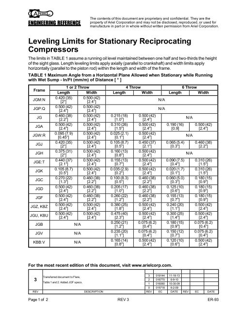
ENGINEERING REFERENCEThe contents of this document are proprietary and confidential. They are theproperty of <strong>Ariel</strong> <strong>Corporation</strong> and may not be disclosed, reproduced, or used <strong>for</strong>manufacture in part or in whole without written permission from <strong>Ariel</strong> <strong>Corporation</strong>.<strong>Leveling</strong> <strong>Limits</strong> <strong>for</strong> <strong>Stationary</strong> <strong>Reciprocating</strong>CompressorsThe limits in TABLE 1 assume a running oil level maintained between one half and two-thirds the heightof the sight glass. Length leveling limits apply axially (parallel to crankshaft) and width limits applyhorizontally (parallel to the piston rod) within the length and width of the frame.TABLE 1 Maximum Angle from a Horizontal Plane Allowed when <strong>Stationary</strong> while Runningwith Wet Sump - In/Ft (mm/m) of Distance [ ° ]FrameJGM:NJGP:QJGJGAJGW:RJGJJGHJGE:TJGKJGCJGDJGFJGZ, KBZJGU, KBUJGBJGVKBB:V1 or 2 Throw 4 Throw 6 ThrowLength Width Length Width Length Width0.420 (35)[2°]0.500 (42)[2.4°]N/A0.500 (42)[2.4°]0.500 (42)[2.4°]N/A0.460 (38)[2.2°]0.500 (42)[2.4°]0.215 (18)[1.0°]0.500 (42)[2.4°]N/A0.500 (42)[2.4°]0.500 (42)[2.4°]0.310 (26)[1.5°]0.500 (42)[2.4°]0.190 (16)[0.9]0.500 (42)[2.4°]0.095 (7.9)[0.45°]0.500 (42)[2.4°]0.025 (2.1)[0.1°]0.500 (42)[2.4°]N/A0.420 (35)[2°]0.500 (42)[2.4°]0.105 (8.7)[0.5°]0.450 (37)[2.1°]0.065 (5.4)[0.3°]0.460 (38)[2.2°]0.375 (31)[2°]0.500 (42)[2.4°]0.160 (13)[0.8°]0.500 (42)[2.4°]N/A0.440 (37)[2.1°]0.500 (42)[2.4°]0.155 (13)[0.7°]0.500 (42)[2.4°]0.090 (7.5)[0.4°]0.310 (26)[1.5°]0.105 (8.7)[0.5°]0.500 (42)[2.4°]0.035 (2.9)[0.2°]0.500 (42)[2.4°]0.020 (1.7)[0.1°]0.310 (26)[1.5°]0.270 (22)[1.3°]0.460 (38)[2.2°]0.100 (8.3)[0.5°]0.460 (38)[2.2°]0.060 (5.0)[0.3°]0.180 (15)[0.9°]0.500 (42)[2.4°]0.460 (38)[2.2°]0.205 (17)[1.0°]0.460 (38)[2.2°]0.125 (10)[0.6°]0.180 (15)[0.9°]0.500 (42)[2.4°]0.460 (38)[2.2°]0.260 (22)[1.2°]0.460 (38)[2.2°]0.155 (13)[0.7°]0.180 (15)[0.9°]0.500 (42)[2.4°]0.500 (42)[2.4°]0.380 (25)[1.8°]0.500 (42)[2.4°]0.240 (20)[1.1°]0.500 (42)[2.4°]0.500 (42)[2.4°]0.500 (42)[2.4°]0.475 (40)[2.3°]0.500 (42)[2.4°]0.300 (25)[1.4°]0.500 (42)[2.4°]N/A0.250 (21)[1.2°]0.075 (6.2)[0.4°]0.180 (15)[0.9°]0.075 (6.2)[0.4°]N/A0.235 (20)[1.1°]0.075 (6.2)[0.4°]0.150 (12)[0.7°]0.075 (6.2)[0.4°]N/A0.165 (14)[0.8°]0.500 (42)[2.4°]0.120 (10)[0.6°]0.500 (42)[2.4°]For the most recent edition of this document, visit www.arielcorp.com.3Transferred document to Flare,3 019144 11-18-132 016770 6-9-10Table 1 and 2: Added JGF specs.1 016060 10-30-090 015718 6-2-09REV DESCRIPTION REV EC DATE REV EC DATEPage 1 of 2 REV 3 ER-93
ENGINEERING REFERENCEThe contents of this document are proprietary and confidential. They are theproperty of <strong>Ariel</strong> <strong>Corporation</strong> and may not be disclosed, reproduced, or used <strong>for</strong>manufacture in part or in whole without written permission from <strong>Ariel</strong> <strong>Corporation</strong>.Dry SumpCompressors subject to transientmotion, roll, and yaw on board a shipor a floating plat<strong>for</strong>m may require a drysump (“dry” crankcase and separateoil reservoir). See the table <strong>for</strong> limits,which are based on the angle wherethe crankshaft/connecting rods willcontact the oil level causing foaming.The limits assume that the running oillevel is maintained between one halfand two-thirds the height of the sightglass when the frame is level.With a dry sump, drains are supplied ateach end of the compressor frame andan additional oil pump chain oiler isprovided by <strong>Ariel</strong>. The packager mustprovide a lube oil reservoir sized andlocated so that the oil pump has oilsuction regardless of the tilt of the shipor floating plat<strong>for</strong>m. An oil sumpstrainer must be installed in the pumpsuction line at the outlet of theseparate lube oil reservoir (unmountedTABLE 2 Maximum Angle from a Horizontal PlaneAllowed in Transient Motion without Dry SumpFrame a 1 or 2 Throw 4 Throw 6 ThrowJGM:N:P:Q 4° N/A N/AJG 4° 2.5° N/AJGA 6.5° 3.5° 2°JGW:R 1° Use Dry Sump b N/AJGJ 4° 1° Use Dry Sump bJGH 3.5° 2° N/AJGE:T 4° 1.5° 1°JGK 1° Use Dry Sump b Use Dry Sump bJGC 4° 1° Use Dry Sump bJGD 5.5° 2.5° 1°JGF 5° 3° 1.5°JGZ:U,KBZ:U7° 4° 2.5°JGB:V N/A 2° 1.5°KBB:V N/A 1.5° 1°a. The JGI frame, vertical non-balanced compressor, is not to be appliedoffshore.b. Use dry sump as noted if compressor is subject to transient motion.strainer is provided by <strong>Ariel</strong> with a new dry sump compressor). Refer to the <strong>Ariel</strong> outline drawings <strong>for</strong>connection sizes and locations.Page 2 of 2 REV 3 ER-93


