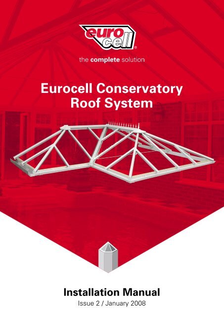
Eurocell Conservatory Roof System - Design Window & Door Systems
Eurocell Conservatory Roof System - Design Window & Door Systems
Eurocell Conservatory Roof System - Design Window & Door Systems
You also want an ePaper? Increase the reach of your titles
YUMPU automatically turns print PDFs into web optimized ePapers that Google loves.
<strong>Eurocell</strong> <strong>Conservatory</strong><strong>Roof</strong> <strong>System</strong>Installation ManualIssue 2 / January 2008
Installation ManualIssue 2 / January 2008IndexContentsStatementGeneral Assemblies – Cross SectionsVictorian/ Edwardian <strong>Roof</strong> InstallationJack Rafter InstallationP Shape <strong>Roof</strong> Installation15-45 Lean To Installation2.2-15 Lean To InstallationBox Gutter InstallationRaised Box Gutter/Guttering InstallationGable Fronted <strong>Roof</strong> InstallationHalf Spider SituationTie Bar InstallationBolster Bar InstallationUpdatesSection No.1234567891011121314
Installation ManualIssue 2 / January 2008Section 1: StatementSection 1:1StatementAll the information in this Installation Manual is provided for guidance only and is given ingood faith, but without warranty or guarantee of any kind, whether implied or expressed. Itmust be understood that <strong>Eurocell</strong> has no control over how the information in this documentis interpreted and therefore cannot be held responsible for any resulting fabrication orproduct failure, howsoever caused.Statutory regulations regarding health and safety of operative’s personnel should be strictlyadhered to. <strong>Eurocell</strong> cannot be held responsible for any failure to comply with them. Thisstatement does not affect your statutory rights.<strong>Eurocell</strong>s policy is to continually improve products, therefore methods, materials andchanges of specification may be made from time to time without prior notice.Updating of Product ManualTo ensure that the Product Manual is kept up to date all registered holders of the saidmanual will be supplied with current amendments immediately upon their release.It is the responsibility of the appointed holder of the manual to ensure that the informationsupplied is correctly inserted into the manual and acceptance returned.For any further information or conformation regarding the current issue of the <strong>Eurocell</strong>Technical Publication, please contact the <strong>Eurocell</strong> Technical Department.
Installation ManualIssue 2 / January 2008Section 1: StatementSection 1:2<strong>Roof</strong> Anatomy
Installation ManualIssue 2 / January 2008Section 2: General Assemblies – Cross SectionsSection 2:1Rafter AssembliesCRS8016CRS8016CRS8501ACRS8500ACRS8011CRS8011RAFTERASSEMBLYLIGHTWEIGHTRAFTERASSEMBLYCRS8017CRS8018CRS8502ACRS8503ACRS8012CRS8012EDWARDIANASSEMBLYVICTORIANASSEMBLYCRS8019CRS8015CRS8019CRS8504ACRS8504ACRS8011CRS8011CRS8014GABLE RAFTERASSEMBLYGABLE RAFTERASSEMBLY(AGAINST WALL)
Installation ManualIssue 2 / January 2008Section 2: General Assemblies – Cross SectionsSection 2:2Rafter Assemblies (Aluminium Top Caps)CRS8517ACRS8516ACRS8501ACRS8502ACRS8011CRS8012RAFTERASSEMBLYEDWARDIANASSEMBLYCRS8518ACRS8516ACRS8503ACRS8500ACRS8012CRS8011VICTORIANASSEMBLYLIGHTWEIGHTRAFTERASSEMBLYCRS8519ACRS8015CRS8519ACRS8504ACRS8504ACRS8011CRS8011CRS8014GABLE RAFTERASSEMBLYGABLE RAFTERASSEMBLY(AGAINST WALL)
Installation ManualIssue 2 / January 2008Section 2: General Assemblies – Cross SectionsSection 2:3Ring Beam & Valley AssembliesCRS8053CRS8551ACRS8553ACRS8207RWK G4CRS8051CRS8059RING BEAMASSEMBLYCRS8553ACRS8050CRS8551ARING BEAMASSEMBLY WITHINTEGRAL GUTTERCRS8059CRS8041EWS8544AEWS8543ACRS8042VALLEY ASSEMBLY
Installation ManualIssue 2 / January 2008Section 2: General Assemblies – Cross SectionsSection 2:4Ridge AssembliesCRS8021CRS8525ACRS8521ACRS8028CRS8069RIDGE ASSEMBLYCRS8021CRS8520ACRS8028CRS8069FIXED PITCHRIDGE ASSEMBLY
Installation ManualIssue 2 / January 2008Section 2: General Assemblies – Cross SectionsSection 2:5Wall Plate AssembliesCRS 8021CRS 8525ACRS 8522ACRS 8028CRS 8069WALL PLATE ASSEMBLYCRS 8080CRS 8480CRS 8582ACRS 8024CRS 8580ACRS 8081LEAN TO ASSEMBLY
Installation ManualIssue 2 / January 2008Section 2: General Assemblies – Cross SectionsSection 2:6Box Gutter AssembliesCRS8053CRS8551ACRS8553ACRS8552ACRS8058CRS8458BOX GUTTERASSEMBLYUB275CRS8059CRS8554ACRS8553ACRS8551ACRS8050CRS8054INTEGRAL BOXGUTTER ASSEMBLYUB225CRS8059
Installation ManualIssue 2 / January 2008Section 2: General Assemblies – Cross SectionsSection 2:7Raised Box Gutter AssemblyCRS 8058ADHESIVE BACKEDINSULATING FOAMCRS 8558AUB250 UTILITY BOARDCRS 8557ACRS8058UB225 UTILITY BOARDADHESIVE BACKEDINSULATING FOAM
Installation ManualIssue 2 / January 2008Section 3: Victorian/Edwardian <strong>Roof</strong> InstallationSection 3:11) Fit the first section of RingBeam into position ensuring itscorrect location. Remember to fitthe External Trim beforepositioning (or Integral gutter ifused).2) Join remaining sections of RingBeam together using both thePressed and Flat Steel Cleats.3) Fix the Ring Beam to the<strong>Window</strong> Frames from the inside ofthe windows through into the RingBeam using 4.8dia. self-tappingscrews at a maximum of 600mmbetween fixings.RidgeVariableSupportRidgeGlazing Trim4) Hook into position on the Ring Beam the Ring Beam Variable Support. Slide theappropriate number of double studs (for the rafter) and Single Studs (for the Hipsand Gable Rafter) down the Ring Beam Variable Support. NOTE: The studs mustbe fitted to EACH individual Ring Beam Variable Support as they are fitted.Wall RafterGutter5) Whilst at floor level, ensure theRidge Variable Support and theRidge Glazing Trim has beenpositioned within the Ridge, andthat the Nylon Threaded Bar hasbeen fitted to the Spider Bracket.Slide the appropriate number ofDouble studs down the RidgeVariable Support for Rafter andSingle studs for Gable Rafter.6) Raise the assembled Ridge upto its correct height andtemporarily support. Loosely fitthe Gable Rafters complete withWall Rafter Gutter to the Ridgeand Ring Beam.7) Fix the Hips complete withSpider Bar Moulding on to theSpider Bar. Fix the Hips onto theRing Beam using Single Studs.Align the centre line of the Hipswith the center of the Spider Bar.Once aligned, tighten the GrubScrews.
Installation ManualIssue 2 / January 2008Section 3: Victorian/Edwardian <strong>Roof</strong> InstallationSection 3:2Ensure leadfinishes insidethe Wall RafterGutter9) Fix the Gable Rafters to theWall using appropriate fixings.3 Places per Rafter.10) Cut to length and fit the EavesBeam Seal into the Ring BeamVariable Support. DO NOT removeprotective tape at this time.(This may have been performed byyour supplier).11) Carry out the Lead Flashing.The method and style of this isleft to the installer although theflashing should finish inside theWall Rafter Gutter. DO NOT flasharound the Ridge at this point.12345 1824 53 6712) Fit a Glazing Stop and EndCap (Rafter/ Hip or Gable Rafter)to each Glazing Bar.13) Fit the Glazing End Trim to theGlazing. If using Polycarbonate,peel back the protective film toenable the fitting of the End Trim.Seal End Trim using a suitablesilicone sealant.14) The order of Glazing should bedone in a specific way. Panelsthat sit on a Hip should be donefirst. So in the example shown,glaze panels 1 to 5 or 1 to 8before glazing any others.24/253215) To Glaze, slide the Glazingpanel on to the Rafters/ Hips andslide into the Ridge Glazing Trim ifapplicable (Remember to removeprotective film if usingpolycarbonate).16) Remove the protective tapefrom the Eaves Beam Seal, pullback the Glazing Sheet to theGlazing Stop and seat onto theSeal. Pull back tape film 1-2inches and fold to inside ofconservatory. Position glazingensuring it is sealed down onglazing stops. Peal away tape filmand pat glazing down fromoutside.17) Once the Glazing is in positionthe Hip Top Caps can be fitted,making sure they butt unto theRidge End Sealing Assembly.
Installation ManualIssue 2 / January 2008Section 3: Victorian/Edwardian <strong>Roof</strong> InstallationSection 3:3Secure sealingassembly bytightening thisnut18) Fit the Ridge End SealingAssembly.19) Before fitting the Ridge TopCap, apply a continuous bead ofStelmax gap filler to all areas ofthe Ridge Flashing Trim where theTop Cap will locate, then slide theFlashing Trim onto the pre cutRidge Top Cap.20) Apply a continuous bead ofStelmax gap filler to the oppositeend of the Ridge Top Cap wherethe Ridge End Top Cap will fit andslide the Ridge End Top Cap ontothe pre cut Ridge Top Cap and fixusing Poly Top Screws.21) Fit the assembled Ridge TopCap onto the Ridge. Beforepositioning, apply a mastic/silicone seal to the areas of theRidge Flashing Trim that butt upto the wall. Now secure the TopCap into position.6 7 9 1022) Complete the Lead Flashingaround the Ridge Flashing Trim.ScrewDecorativeBoss ontonylon treadedbar23) The Finial and Crestings cannow be slid down the Ridgechannel.In certain casesthe End Cap mayneed to bescribed to suitthe roof pitch89111224) Glaze the remaining panels in the order shown, ensuring that the glazingis inserted into the Ridge Glazing Trim and is seated on the Eaves Beam Seal.Fit the Glazing Bar Top Caps ensuring they are in the correct position and buttup to the Ridge Glazing Trim.25) Fit the Ridge Bottom Cap andthe Ridge Radius End Bottom Cap.
Installation ManualIssue 2 / January 2008Section 3: Victorian/Edwardian <strong>Roof</strong> InstallationSection 3:426) Fit the Internal Ring Beam Trims to the Ring Beam.27) Apply glue to ONE inside face of the Ring Beam Joint Trim.28) Fit the Trim to the Joint between the two Ring Beam Internal Trims.Repeat this process for all other Joints.
Installation ManualIssue 2 / January 2008Section 4: Jack Rafter InstallationSection 4:1This section of the Installation Guide covers fitting of Jack Rafters onto Glazing Bars.1) Slide the Jack Rafter Bar intothe Jack Rafter as shown. DONOT fix into place at this stage.2) Place the Jack Rafter intoposition, locating the Jack RafterBar onto the Jack Rafter Fixingand onto the Double Studs at theRing Beam End. Tighten all nuts.3) Secure the Jack Rafter Bar inposition as shown.4) All glazing can now be carriedout. When fitting the Top Caps,ensure that the Joint between theHip Top Cap and the Jack RafterTop Cap is sound.5) Apply silicone sealant aroundjoint between the hip top cap andjack rafter top cap
Installation ManualIssue 2 / January 2008Section 5: P Shape <strong>Roof</strong> InstallationSection 5:1This section of the Installation Guide covers the installation procedures for the following:1) P Shape style <strong>Conservatory</strong> <strong>Roof</strong>2) ValleyW all PlateRidge G lazing TrimW all PlateVariable Support1) Before the installation of theroof commences, fit the fixingcleats to the Wall Plate as shown.It is not necessary to locate thescrews through the holes incleats.2) Fit the Wall Plate VariableSupport complete with GlazingTrim to the Wall Plate. Slide aSingle Stud (for Valley) andDouble Studs down the VariableSupport for the Glazing Bars.3) Move the Wall Plate intoposition and fix the back to thewall at a maximum of 600mmcentres. Now fix the Ridge to thefixing cleats previously fitted onthe Wall Plate.Double Sided Tapelug is facingupwards4) Before fitting of the Valleycommences, ensure that theValley Double Sided Tape hasbeen fitted in the position shownon both wings of the Valley. (DoNot remove the backing tape atthis time).5) Position and fix the first wingof the Valley ensuring theconnecting lug is facing upwards.Do Not fully tighten the nuts atthis stage.6) Now fit the other wing of theValley ensuring that the assemblyis in the centre of both the Ridge/Wall Plate and Ring Beam.
Installation ManualIssue 2 / January 2008Section 5: P Shape <strong>Roof</strong> InstallationSection 5:2Push glazinginto glazingtrim and slideinto positionBed down theglazing ontothe doublesidedtape7) Pull back tape film 1-2 inchesand fold to inside of conservatory.Position glazing ensuring it isseated down on glazing stops.Peel away tape film and patglazing down from outside.If the Jack RafterBar has not beenfitted refer toSection 2:18) When glazing around theValley, always start at the topnear the Ridge and work down,i.e. in the order 1 to 6 on theexample shown.9) On some occasions it may benecessary to glaze panels 1 and 2before the Jack Rafters are fitted.In this situation push the Glazinginto the Ridge Glazing Trim andslide into position. Bed down theglazing onto the Valley DoubleSided Tape.10) Slide a 30mm long M6 Bolt upthe channel in the Valley andsecure the Jack Rafters intoposition at both ends. Fully tightenthe bolts at both ends of theValley.11) Fit the remaining Glazing Barsready for Glazing.12) When all Glazing is complete,the Glazing Bar Top Capsincluding the Valley Top andBottom Caps can be fitted.13) Once the Ridge and Wall PlateTop Caps have been fitted, theRidge Top cap Corner Trim can befitted. Apply Stelmax Gap Filler tothe under side of the Corner Trim.14) Locate the Corner Trim and fixusing Poly Top screws in theposition shown. Remove anyexcess gap filler.
Installation ManualIssue 2 / January 2008Section 6: 15-45 Lean To <strong>Roof</strong> InstallationSection 6:1This Section of the Installation Guide contains guidelines for a 15-45 Lean To <strong>Conservatory</strong>.There are two methods of fixing the Wall Plate, which depends on the following information:1) Wall Plate, Wall Plate Variable Support and Glazing Trim unassembled, use METHOD 12) Wall Plate, Wall Plate Variable Support and Glazing Trim pre-assembled at the correct angle, use METHOD 2Method 11) Support the Wall Plate in position. Once satisfied with its position, drill through the Wall Plate andinto the host wall. Fix the Wall Plate into the wall using appropriate fixings. If required, use packingbehind the Wall Plate if the wall is not even.2) Fit the Wall Plate VariableSupport complete with GlazingTrim to the Wall Plate. Slidesufficient Double and SingleStuds into the Variable Supportfor the Glazing Bars.3) Fit the Ring Beam onto the<strong>Window</strong> Frames as describedearlier in this guide. Fit the RingBeam Variable Support into theRing Beam and slide sufficientSingle and Double Studs downfor the Glazing Bars.4) Fix the Gable Raftersinto position. (fix back towall if applicable,remembering to fit theWall Rafter Gutter).5) Fix remaining Rafters intoposition, checking all centresas you go.6) Fix the Wall Plate Top Capinto position and Lead Flashas shown in the diagramabove. The Wall Plate BottomCap can also be fitted at thisstage. As shown opposite.7) Cut and fit the Eaves BeamSeal into position. DO NOTremove protective tape at thistime. END OF METHOD 1Proceed to section 6:2Method 21) Lay the pre-assembledWall Plate complete withsufficient Single andDouble Studs on top of the<strong>Window</strong> Frames.2) Fit the Ring Beam onto the<strong>Window</strong> Frames as describedearlier in this guide. Fit theRing Beam Variable Supportinto the Ring Beam and slidesufficient Single and DoubleStuds down for the GlazingBars.3) Fix the Gable Raftersinto position.4) Lift the Wall Plateassembly into positionensuring it is level bothhorizontally and vertically.Fix through the wholeassembly into the wall.As shown opposite5) Fix remaining Raftersinto position, checking allcentres as you go.6) Fix the Wall Plate Top Capinto position and Lead Flashas shown in the diagram. TheWall Plate Bottom Cap canalso be fitted at this stage.7) Cut and fit the Eaves BeamSeal into position. DO NOTremove protective tape at thistime. END OF METHOD 2
Installation ManualIssue 2 / January 2008Section 6: 15-45 Lean To <strong>Roof</strong> InstallationSection 6:28) Fit the Glazing Stops andGlazing Bar End Caps as describedearlier in this guide.9) Fit the Glazing End Trims to theGlazing, apply silicone along endtrim before fitting. If usingpolycarbonate, peel back enoughprotective tape to allow fitting ofthe End Trims.10) Slide the Glazing onto theRafters and into the Ridge/WallPlate Glazing Trims.11) Remove the protective tapefrom the Eaves Beam Seal, pulldown Glazing to the Glazing Stopand seat onto the Eaves BeamSeal. (If using polycarbonate,remove protective film).12) Once the Glazing is inposition, snap on the Glazing BarTop Caps ensuring they aresnapped into the correct positionand that they are butted up to theRidge Glazing Trim. Fold up andclip the Glazing Bar End Caps intoposition.13) The Ring Beam End Cap cannow be fitted. To fit the End Cap,first cut down the capping to suitthe pitch of the roof as shown.14) Apply a bead of neutral curesilicone to the areas of the EndCap that locate onto the RingBeam. Then place into position.15) Fit the Gable End Trim ontothe Gable Rafters (If they are notadjacent to a wall).16) Apply a bead of neutral curesilicone seal to the areas of theHalf Ridge Gable End Cap that willsit on the Wall Plate Top Cap.17) Position the Gable End Capinto its correct position.
Installation ManualIssue 2 / January 2008Section 7: 2.5-15 Lean To <strong>Roof</strong> InstallationSection 7:1The installation of this style of conservatory roof is similar to that of the 15-45 style of roofGLAZING TRIMWALL PLATEVARIABLE SUPPORT1) Support the Wall Plate inposition. Drill through the WallPlate into the host wall. Fix theWall Plate to the wall using theappropriate fixings. (Use packing ifrequired).2) Hook the Variable Support intoposition as shown and then fit theRidge Glazing Trims. Slidesufficient Double Studs down theVariable Support for the Rafters(Not the Gable Rafters).3) Fit the Ring Beam onto thewindow frames as describedearlier and fit the Ring BeamVariable Support complete withenough Double Studs for theRafters.4) Attach the Gable Rafters toeither the <strong>Window</strong> Frames, InfillPanel or Timber Framework.5) Fix the Rafters into positionchecking the centres as you go.6) Fit the Lean to Seal onto theLean To Variable Support andGlazing Trim as shown. Then fitthe Lean To Top Cap and carryout the Lead Flashing onto it. TheLean To Bottom Cap can also befitted at this point.Any other installation information for the 2.5-15 Lean To style conservatory is the same as for the 15-45 roof with theexception of the Lean To End Caps. The Installation guidelines for these are as follows.7) Apply a bead of neutral curesilicone to the lip of the End Capthat sits onto the Lean To TopCap. Then locate the End Capsinto their correct position.
Installation ManualIssue 2 / January 2008Section 8: Standard Guttering InstallationSection 8:1BOX GUTTERBOX GUTTERAPPLY SILICONEALONG FRAMEFASCIA BOARD RETAINING TRIMWINDOW FRAME1) The Box Gutter should rest onthe <strong>Window</strong> Frames. Beforepositioning, apply a neutral curesilicone on all areas of the<strong>Window</strong> Frame where the BoxGutter will sit.2) Before positioning, locate theBox Gutter Insulation Trim intoposition on the Box Gutter. TheBox Gutter can then be raised intoposition.RING BEAMVARIABLE SUPPORTWALL ANCHORRING BEAM3.9 x 16 SELF TAPPINGSCREW3) Drill through the Box Gutter intothe host wall. The Box Gutter canthen be fixed to the wall usingappropriate fixings at a maximum of600mm centres.4) Position and fix the Ring Beamcomplete with Variable Support tothe Box Gutter at 600mmmaximum centres. Ensuring thatsufficient Double and Single Studsare positioned within the VariableSupport.LEAD FLASHINGADHESIVE BACKEDINSULATING FOAMBOX GUTTERUNDER CLADDINGRING BEAMINTERNAL TRIM5) Offer up and position the Box Gutter under Cladding. Whilst supporting,fit the Ring Beam Internal Trim. The Lead Flashing can now be fitted.
Installation ManualIssue 2 / January 2008Section 9: Box Gutter Adaptor Installation/Guttering InstallationSection 9:1The Following is a guide on how to fit a box gutter adaptor.1) Before attempting to fit theadaptor, ensure that the insideedge of the Box Gutter is fully De-Burred.2) Smear soapy water on theinside face of the Box Gutterwhere the Adaptor will locate andto the seal that is fitted on theAdaptor.3) Push the Box Gutter Adaptorinto position as shown.4) Position the Box Gutter Brace inthe Groove on the adaptor withone part of the Brace hooked intoposition.5) To fit the other section of theBox Gutter Brace, lower it intoposition and then apply pressurein the position shown to causecompression to enable the braceto be clipped into position.Guttering Installation6) To join the adaptor ontoexisting standard guttering, use astraight union.1) Gutter Brackets must be fittedat a maximum of 600mm centresand no more than 200mm fromeach corner. The Gutter Bracketsare located in the Ring BeamExternal Trim and are twisted intoposition as shown.2) To clip the Guttering intoposition, clip the front part of theGutter Bracket into the Guttersection.3) Rotate the rear section of theGutter up and clip into position.It is assumed that the installer has knowledge of Guttering so only instructions specific to <strong>Eurocell</strong> components are given.
Installation ManualIssue 2 / January 2008Section 10: Gable Fronted <strong>Roof</strong> InstallationSection 10:1On a Gable End style conservatory, both Internal and External Gable End Caps are required.1) Apply a bead of neutral curesilicone to the areas of the pre-cutRidge Top Cap that the ExternalEnd Cap will fit.2) Position the External End Cap inits correct location as shown.3) The External Gable End Trimmust be cut to the required roofpitch.4) Slide the End Trim onto theRidge Bottom Cap.5) When installing, apply a neutralcure silicone or mastic seal ontothe face of the trim that is againstthe <strong>Window</strong> Frames. Now fitRidge Bottom Cap complete withEnd Trim.
Installation ManualIssue 2 / January 2008Section 11: Half Spider SituationSection 11:14) Fit the Gable Bar complete withGable Bar Moulding to the HalfSpider Bracket, loosely fit theother end onto the Ring Beamusing a Double Stud.5) Fix the Gable Bar to the wallusing appropriate fixings.3 Places.6) Fix the Hip(s) complete withSpider Bracket Mouldings to theHalf Spider Bracket. Fix the Hip(s)onto the Ring Beam using SingleStuds. Align the centreline of theHips with the centreline of theThreaded Bar. Once alignedtighten Grub screws.7) Fit a Glazing Stop and End Cap(Rafter/Hip or Gable Rafter) toeach Glazing Bar.8) Cut to length and fit the EavesBeam Seal into the Ring BeamVariable Support. DO NOT removeprotective tape at this time.9) Carry out the Lead Flashing.The method and style of this isleft to the installer although theflashing should finish inside theWall Rafter Gutter. DO NOT flasharound the Ridge at this point.
Installation ManualIssue 2 / January 2008Section 11: Half Spider SituationSection 11:210) Fit the Glazing End Trim to theGlazing, apply silicone along endtrim before fitting. If usingpolycarbonate, peel back theprotective film to enable the fittingof the End Trim.11) The order of Glazing should bedone in a specific way. Panelsthat sit on a Hip should be donefirst. So in the examples shown,glaze panels 1 to 4 or 1 to 3before glazing any others.12) To Glaze, slide the GlazingPanel onto the Rafters/Hips andslide into the Ridge Glazing Trim ifapplicable. Remember to removethe protective film is usingpolycarbonate.24/253213) Remove the protective tapefrom the Eaves Beam Seal, pullback the Glazing sheet to theGlazing Stop and seat onto theSeal.Apply a stelmaxgap filler along thisface prior toassembly14) Fit the Half Ridge End sealingassembly.15) Once the Glazing is inposition, the Hip Top Caps can befitted, making sure they butt up tothe Half Ridge End Sealingassembly. Note if 32mm Glazing isbeing used, clip the Top Caps intoits first position as shown.Apply asilicone beadalong back ofthis facewhere cappingbutts up towallFix cappingusing PolyTop screw16) Before fitting the Half Ridge Top Cap, applystelmax gap filler to the area that the Half RidgeEnd Top Cap will fit, slide the Half Ridge EndTop Cap into position and fix using a Poly Topscrew. Fit the Half Ridge Top Cap assembly ontothe Ridge. Before positioning apply amastic/silicone seal to the areas of the HalfRidge End Top Cap that will butt up to the wall.Secure the assembly into position. The leadflashing can now be completed.
Installation ManualIssue 2 / January 2008Section 12: Tie Bar InstallationSection 12:1NOTE: The Tie Bars are fitted BEFORE glazing of the roof commencesDECORATIVE COVERGeneral Assembly of Tie BarsUse Tie Bar Bracketas a guide for drillinghole centres.Silicone aroundNut and Boltassembly.1) Fit the Tie Bar Bracket on thespecified Rafter in the positionshown. Using the Bracket as aguide, mark through the hole centresand drill through the Rafter andBottom Cap with a 6.5mm diameterdrill.2) Fix the Tie Bar Bracket to theRafter using the screws and nutsprovided. Once tightened, apply asilicone around the nut and boltassembly.3) Fix the Ridge Tie Bar Bracket tothe underside of the Ridge using selftappingcountersunk screws.
Installation ManualIssue 2 / January 2008Section 12: Tie Bar InstallationSection 12:24) Cut the vertical Tie Bar Rod sothat the Centre Boss will align withthe Rafter Tie Bar Brackets. Screwthe vertical Tie Bar Rod into theClevis Bracket and connect to theRidge Tie Bar Bracket using the M10x 30 nut and bolt. Push fit the PVCnut and bolt covers. Slide onto theRod sufficient PVC Rod cover.Position the Centre Boss at thecorrect height by inserting theVertical Tie Bar through the topjunction and securing with an M10bolt.5) Cut a length of Tie Bar Rod toproduce the horizontal Tie Bar.Screw one end into a Clevis Bracket.Connect the Clevis Bracket to theRafter Tie Bar Bracket using the M10x 30 nut and bolt. Fit the PVC nutand bolt covers. Slide onto the Rodsufficient PVC rod cover. Connectthe rod to the centre boss throughthe side junction and secure with anM10 bolt. Repeat this process forthe other side.6) Once satisfied that all Tie Rodsare correctly positioned, fully tightenall fixings within the central boss.7) Fit centre boss decorative platesby screwing together.
Installation ManualIssue 2 / January 2008Section 13: Bolster Bar InstallationSection 13:1Fitting of standard Bolster Bar CappingsBolsterBarSTANDARD RAFTERASSEMBLYVICTORIAN HIPASSEMBLYBolsterBarCappingEDWARDIAN HIPASSEMBLY1) The Bolster Bars come preassembledonto their correspondingRafters. These Rafters should befitted in the conventional way.2) Once all internal trims are inposition the Bolster Bar Capping andEnd Caps can be cut.Option 1 – Cut the cappings sothat they are flush with each endof the Bolster Bar. Clip fit theCappings into place. Please notethat the end cap mouldings willneed fitting at both ends for thisoption. Before fitting themouldings they will require cuttingto the correct angle (see fig.1).Push fit the mouldings making surethe pins on the mouldings locateinto the ports in the bolster bar.Cut moulding to thisline for Victorian HipMoulded anglesuits EdwardianHipOption 2 – Cut the cappings sothat they are flush at theRidge/Wall Plate end of thebolster bar, scribe and cut theopposite end into the InternalRing Beam Trim. Clip fit themouldings to the required angle(see fig.1) Push fit themouldings making sure the pinson the mouldings locate into theports on the Bolster Bar.Cut moulding tothis line forStandard RafterEnd Cap
Installation ManualIssue 2 / January 2008Section 13: Bolster Bar InstallationSection 13:2Fitting of Heavy Duty Bolster Bar CappingsBolsterBarCappingHeavy DutyBolsterAssemblySTANDARD RAFTERASSEMBLYVICTORIAN HIPASSEMBLYEDWARDIAN HIPASSEMBLY1) The Heavy Duty Bolster Barscome pre-assembled onto theircorresponding rafters. These raftersshould be fitted in the conventionalway.Moulded anglesuitsEdwardian Hip2) Once all internal trims are inposition the Heavy Duty Bolster BarCappings and End Caps can be cutand fitted. There are two optionsavailable for the fitting of thecappings.Cut mouldingto this line forVictorian HipOption 1 – Cut the Cappings sothat they are flush with each endof the Bolster Bar. Apply acontinuous bead of silicone toinside bottom face of thecappings and push into position.Please note that the End CapMouldings will need fitting atboth ends for this option. Beforefitting the moulding correctangle. (see fig.1) Push fit themouldings making sure that thepins on the mouldings locate intothe ports in the Bolster Bar.Option 2 – Cut the Cappings sothat they are flush at theRidge/Wall Plate end of theBolster Bar, scribe and cut theopposite end into the InternalRing Beam Trim. Apply acontinuous bead of silicone tothe inside bottom face of theCappings and push into positioncut the moulding to the requiredangle (see fig.1). Push fit themoulding making sure the pinson the mouldings locate into theports on the Bolster Bar.Cut moulding tothis line forStandard RafterEnd Cap
Installation ManualIssue 2 / January 2008Section 14: UpdatesSection 14.1Updates
Installation ManualIssue 2 / January 2008Section 14: UpdatesSection 14.1Updates
www.eurocell.co.uk<strong>Eurocell</strong> Profiles Ltd, Fairbrook House, Clover Nook Road, Alfreton, Derbyshire DE55 4RFTel: 01773 842100 Fax: 01773 838633 marketing@eurocell.co.uk


