⢠⢠⢠New Features and Improvements of SEMA V11.2 Build 5800
⢠⢠⢠New Features and Improvements of SEMA V11.2 Build 5800
⢠⢠⢠New Features and Improvements of SEMA V11.2 Build 5800
Create successful ePaper yourself
Turn your PDF publications into a flip-book with our unique Google optimized e-Paper software.
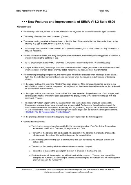
<strong>New</strong> <strong>Features</strong> <strong>of</strong> Version 11.2 Page: 5/12• The font size <strong>of</strong> text <strong>and</strong> dimension lines has been revised <strong>and</strong> the smallest font size is now 0.01mm. This hasbrought great advantages when labelling <strong>and</strong> dimensioning a detail in combination with the font size “zoom”<strong>and</strong> the font size “free”.• The positioning comm<strong>and</strong> for 3D objects with reference (click) to dimension lines has been revised. (Sebalex)Ro<strong>of</strong> Design• In version 11.2 separate ro<strong>of</strong> areas can be displayed with individual textures. In order to do this an "Look“ tabhas been added to the ro<strong>of</strong> area master data. This contains a reference field for a texture which can be usedin both the textured 3D representation <strong>and</strong> in the photo-realistic representation. The texture in the ro<strong>of</strong> areareference field overrides thus the global texture <strong>of</strong> the ro<strong>of</strong> tiles as set in the general colour settings. Ro<strong>of</strong>areas without a texture reference will use the global tile texture. Also on the active ro<strong>of</strong> structure, the texture<strong>of</strong> the ro<strong>of</strong> area will be displayed in the topmost layer.It is now possible to set the optical appearance <strong>of</strong> the ro<strong>of</strong> area via the "Texture“ comm<strong>and</strong>. The highlightedro<strong>of</strong> area also can be assigned any kind <strong>of</strong> texture master data by using the editing comm<strong>and</strong> "Texture“. Theentry into the master data <strong>of</strong> the ro<strong>of</strong> surface area takes place automatically.Ro<strong>of</strong> constructions, such as dormers with metal plating ro<strong>of</strong>, overhang glazing or conservatories, ro<strong>of</strong>gardens, shingled ro<strong>of</strong>s, etc. can now be visualised perfectly. (Röhrig, Jobega, Staudenschreiner <strong>and</strong> manyothers). Printing & Plotting• A so-called printer calibration is now available under "Extras“ → "Options“. This allows you to respond todifferences in measurement between the print preview in the program <strong>and</strong> the actual print-out on paper. Howto proceed: a square, which will fit onto the print-out, needs to be printed to the scale <strong>of</strong> 1:1. After this, theprint-out is checked. Then the printer in question must be set by selecting "Printer Calibration“ from themenu. Then the target measurements <strong>and</strong> the actual measurements in the X/Y direction need to be entered.The program now calculates the "correction factor“ by itself. If the menu is ended with "OK“, the correctionsfor the respective printer are saved.Room Planner• Up until now, the following areas <strong>of</strong> a room have been evaluated in the material list: the gross area, the netarea, the height, the perimeter <strong>and</strong> the gross volume. In addition, the system limit was evaluated.In version 11.2 the creation comm<strong>and</strong> “Room” has been revised <strong>and</strong> improved greatly. The following areas<strong>and</strong> structures are now incorporated into each room: the room floor area, the room wall area, the roomceiling area <strong>and</strong> the room inclined areas. Additionally, the so-called complete system limit is evaluated.For new room areas, the following data is now evaluated:For the room's floor space, the gross floor space, the net floor space <strong>and</strong> the perimeter are evaluated. Tocalculate the room's floor space, the area <strong>of</strong> the room's floor is used with the area <strong>of</strong> the underlying topceiling layer. By using the floor area, the cutouts in the top ceiling layer will be included. Subject to presettings(alt+7), cutouts such as holes in the ceiling (for stairwells) will be deducted from the net area <strong>of</strong> theroom's floor space. Cutouts will not be included in the calculation <strong>of</strong> gross areas <strong>of</strong> room floor space.For the wall areas <strong>of</strong> a room, the gross <strong>and</strong> net areas are evaluated. In order to calculate the wall areas, thewall area <strong>of</strong> the vertical room area is used with the corresponding area <strong>of</strong> the innermost layer <strong>of</strong> the wall. Byusing the area <strong>of</strong> the vertical room area <strong>and</strong> the innermost layer <strong>of</strong> the wall, cutouts can be incorporated. Sothat the wall areas are identified correctly, the distance between the room level <strong>and</strong> the innermost layer <strong>of</strong>the wall must not be greater than 5mm. The gross <strong>and</strong> net areas are distinguished as follows: for the grossarea, the maximum height between the floor <strong>and</strong> ceiling is assumed <strong>and</strong> this area is <strong>of</strong>fset <strong>and</strong> intersectedwith the innermost layer <strong>of</strong> the wall. Window <strong>and</strong> door cutouts are not included in the gross area. For the netarea, the vertical area <strong>of</strong> the room is <strong>of</strong>fset <strong>and</strong> intersected with the innermost layer <strong>of</strong> the wall. Floor <strong>and</strong>ceiling structure are taken into account when calculating the net area. Subject to pre-settings (alt+7), window<strong>and</strong> door cutouts will be deducted from the net area. Currently, the area <strong>of</strong> subtraction for the cutouts iscalculated by using the zero-layer area.The gross area, net area <strong>and</strong> the perimeter <strong>of</strong> the ceiling are evaluated for the room's ceiling area.In order to calculate the ceiling area, the ceiling area <strong>and</strong> the overlying area <strong>of</strong> the undermost ceiling layerare used. By using the ceiling area, the cutouts in the undermost ceiling layer can be incorporated. Subjectto pre-settings (alt+7), cutouts, such as holes in the ceiling, can also be incorporated into the net area <strong>of</strong> theceiling.For a room's inclined area, the gross <strong>and</strong> the net areas <strong>of</strong> the ceiling are evaluated. In order to calculate theinclined areas, the surface area <strong>of</strong> the inclined areas is used with the corresponding ro<strong>of</strong> surface area.Subject to pre-settings (alt+7), cutouts in the ceiling, for example for chimneys <strong>and</strong> ro<strong>of</strong> windows, will be<strong>SEMA</strong> GmbH • Dorfmühlstraße 7-11 • 87499 Wildpoldsried, Germany • phone + 49 8304 939-0 • fax +49 8304 939-245http://www sema-s<strong>of</strong>t.com • e-mail: support.en@sema-s<strong>of</strong>t.com
<strong>New</strong> <strong>Features</strong> <strong>of</strong> Version 11.2 Page: 6/12incorporated into the inclined area <strong>of</strong> the room. Cutouts are deducted from the net area <strong>of</strong> inclined areas butfor gross areas added. The areas <strong>of</strong> dormers are treated as areas <strong>of</strong> the main ro<strong>of</strong> <strong>and</strong> are added to theinclined areas.The total system limit is derived from the total <strong>of</strong> all system limits including the floor <strong>and</strong> ceiling areas.In the material list, the partial list "Room“ under the tab called "Material List <strong>and</strong> Stairs“ has been extendedto include the new room areas. The partial list has been divided into the following sub-groups:room areas, room areas sorted by area, system limits, living space, living space by storey, living space total,GFA gross floor area, GFA gross floor area total, NFA net floor area, NFA net floor area total, GRV grossroom value <strong>and</strong> NRV net room volume. In addition, the new "Room List“ is available in which only roomareas are evaluated.In the partial list called "Room Areas“ all areas <strong>of</strong> a room (ceiling area, floor space, wall area <strong>and</strong> slopingwall area) will be listed <strong>and</strong> sorted by storey.In the partial list "Room Areas sorted by area“ is structured just like the partial list "Room Areas“: This list issorted by the areas <strong>of</strong> rooms (ceiling area, floor space, wall area <strong>and</strong> inclined areas) <strong>and</strong> storey . Hence it ispossible to quickly calculate, for example, the existing square-metre area <strong>of</strong> walls per building.Every individual system limit <strong>of</strong> a building is listed in the partial list "System Limit“. “ In addition to this, the"System Limit Total“ is also evaluated in this list.The partial list called "Living Space“ is structured so that the net area <strong>of</strong> each individual room is calculated.In the two sub-groups "Living Space by storey“ <strong>and</strong> "Living Space total“, the net area per storey or the totalnet area <strong>of</strong> all the rooms in the building are listed.The partial list called "GFA Gross Floor Area“ is generated by using the gross area <strong>of</strong> the system limits. The"gross floor area“ is the sum <strong>of</strong> all the building's floor areas on each storey. The area <strong>of</strong> the walls is nottaken into account when calculating the gross floor area. The partial list is structured so that the gross areaper storey is evaluated. In the sub-group called "GFA Gross Floor Area Total“, the gross areas <strong>of</strong> all storeysare added up <strong>and</strong> evaluated.The partial list "NFA Net Floor Area“ is generated from the net area <strong>of</strong> the "Room“. The "Net Floor Area“ isthe total <strong>of</strong> the floor areas <strong>of</strong> all ground-plan planes. Wall areas are used in this calculation. This is the maindifference between "gross floor area“ <strong>and</strong> "net floor area“. In this partial list, the gross area per storey <strong>of</strong>“Room” is analysed. In the sub-group "NFA Net Floor Area Total“, the gross area <strong>of</strong> all storeys from "Room“are added up <strong>and</strong> evaluated.The partial list “GRV Gross Room Volume” is calculated from the gross volume <strong>of</strong> the "System Limit Total“.The "gross room volume“ is the total <strong>of</strong> the construction's room volume over the gross floor area. It isenclosed by the outer periphery <strong>of</strong> the construction's base from the outer walls <strong>and</strong> the ro<strong>of</strong> includingdormers. Thus in the partial list "GRV Gross Room Volume“, the gross volume <strong>of</strong> the whole building isevaluated.The partial list "NRV Net Room Volume“ is calculated from the gross volume from "Room“. The "net roomvolume“ is derived from interior room volumes <strong>of</strong> all rooms, whose floor areas belong to "net floor area“. Inthis partial list, the gross volumes <strong>of</strong> all rooms in the building are evaluated.Under "Evaluations“, the tab "Room Areas“ has been added to the pre-settings (Alt+F7). The followingsetting can be used to evaluate room areas.Floor space: It is possible to set up whether floor space net areas are to include cutouts or not. Furthermore,it is possible to set whether all cutouts should be deducted or only those over a certain size. In addition, youcan set up whether door surface areas are to be added to the gross area, to net areas or to gross <strong>and</strong> to netareas. Depending on the direction in which the door opens, its surface area will also be added to the roomon the other side. The whole area (thickness <strong>of</strong> the wall + layer thickness x width <strong>of</strong> the door) will be used. Ifthis option is used, then the perimeter <strong>of</strong> the room's floor space is extended by the width <strong>of</strong> door + layerthickness. The direction in which the door opens is also incorporated.Wall areas, ceiling areas <strong>and</strong> inclined areas: Here it is possible to generally set whether cutouts arededucted from the net area or not. Furthermore, it is possible to set whether all cutouts should be deductedor only those over a certain size• In version 11.2 the ceiling shape master data has been improved. Under the "Look“ tab you can now setwhether the ceiling shape in the visualisation is shown from underneath "open“ (previously the only option)or "closed“. The new effect is shown to an advantage especially with 3D solid ceilings. By using theappropriate settings <strong>of</strong> the texture, the top side, bottom side <strong>and</strong> the side areas <strong>of</strong> the ceiling can bedesigned with different appearances. Structural Physics• In version 11.2 there is the possibility to have the energy performance <strong>of</strong> areas evaluated in the material list.The program automatically recognises the so called “energy performance types”: outside windows, insidewindows, outside doors, inside doors, exterior walls, interior walls, floors, ceilings, ro<strong>of</strong> surface areas <strong>and</strong>collar beam systems. Each <strong>of</strong> these "energy performance types“ evaluates energy performance areas in the<strong>SEMA</strong> GmbH • Dorfmühlstraße 7-11 • 87499 Wildpoldsried, Germany • phone + 49 8304 939-0 • fax +49 8304 939-245http://www sema-s<strong>of</strong>t.com • e-mail: support.en@sema-s<strong>of</strong>t.com
<strong>New</strong> <strong>Features</strong> <strong>of</strong> Version 11.2 Page: 7/12material list. The energy performance area <strong>of</strong> windows <strong>and</strong> doors is calculated by using the width <strong>and</strong> height<strong>of</strong> the structural component. The area <strong>of</strong> exterior <strong>and</strong> interior walls arises from using the length <strong>and</strong> height <strong>of</strong>the timber layer. The calculation always uses the maximum length <strong>of</strong> a wall. Window <strong>and</strong> door cutouts arenot incorporated into the energy performance area. The length <strong>and</strong> width <strong>of</strong> the structural element are usedwhen the energy performance area is calculated for floor <strong>and</strong> ceiling shapes. As before, cutouts are notincorporated. The area <strong>of</strong> a collar beam system is calculated from the intersection between the system limit<strong>and</strong> the ro<strong>of</strong>. The calculation for ro<strong>of</strong> surface areas uses the intersection between the system limit <strong>and</strong> theindividual ro<strong>of</strong> areas.For outside windows, outside doors, exterior walls <strong>and</strong> ro<strong>of</strong> areas an additional alignment is available. Byselecting the comm<strong>and</strong> "View“ → "3D Representation“ → "Set North“, the direction can be determined. Theprogram then automatically determines the direction in terms <strong>of</strong> north, south, east <strong>and</strong> west <strong>of</strong> theaforementioned components in the material list. In addition, each structural element can be assigned a socalled"U-value“ under the material list tab. These can also be used in the transfer into the material lists. Thedata in the material list can then, for example, be transferred to Excel by selecting the comm<strong>and</strong> "File“→"Export Material List“→ "Micros<strong>of</strong>t Excel“. • The list/tab "Structural Physics" has been added to the material list. In order to show this list, it must becreated via the comm<strong>and</strong> "Format” -> “Create new tab-list". In this list all "Energy performance types" arelisted individually as well as in groups. Structural physical values such as alignment, pitch, energyperformance areas <strong>and</strong> U-values are evaluated for each component. In addition, the "Enclosed room" is alsoevaluated in the new list. Coverings 3D Wall Ceiling• In version 11.2 the horizontal section has been added to the wall view. It is now possible to make the adjacentwalls <strong>of</strong> the horizontal section visible. However, in order to show the abutting walls, they must have a logicalwall connection. With this wall view, it can be checked quickly <strong>and</strong> easily, for example, whether the layershave been correctly intersected. In addition, direct changes to the abutting walls in the horizontal sectionscan be carried out via the editing comm<strong>and</strong> "Change“. The option "Adjacent Walls Visible“ has been addedto the view settings (F7) under "Images+3D“ → “Auto-Sectioning”. Only when this option is activated, theabutting walls will be shown in the horizontal section. In addition, the depth <strong>of</strong> the adjacent walls can beentered. (Vario)• The "Overview Drawing“ in the screen <strong>of</strong> the carpenter's dimensioning or in the single member view has beenextended. Coverings can now also been shown in the overview drawing. For this, the menu point"Coverings“ has been added to the appropriate view settings. Optionally, you can select whether all or onlymarked coverings are to be shown in the overview drawing (display settings (F7), Single Member,Carpenter's Dimensioning <strong>and</strong> Single Member, Overview Drawing). • For the editing comm<strong>and</strong> “Abutting on division line” <strong>of</strong> boards in wall view, the last value entered will be saved.Hence, if it is the same, the distance <strong>of</strong> the boards no longer needs to be re-entered each time they abut.(Büdenbender)• The auto Wall function (F10) has been revised for one special case <strong>of</strong> applying coverings. (Albert-Haus)Single Member• In version 11.2 "Tyrolean dovetailing with Frosch” <strong>and</strong> “Klingschrot” are now available as MCAD processing.Furthermore, the appropriate corner macros have been added. These two new processing options buildupon the "normal“ Tyrolean dovetailing <strong>and</strong> can only be operated by using additional parameters . Just aswith "Tyrolean dovetailing with Frosch”, “Klingschrot” is created so that processing is also visible in 3D. Inthe wall view, it is possible to create the MCAD at the end <strong>and</strong> the beginning <strong>of</strong> the wall or to assign a wall tothe appropriate MCAD. The parameters are pre-populated so that the MCAD processing option can be useddirectly. By entering additional parameters, the processing options can be adapted individually <strong>and</strong> flexibly.The processings are calculated from the start or the end <strong>of</strong> the timber.The following features apply to "Tyrolean dovetailing with Frosch” <strong>and</strong> “Klingschrot”:• The position <strong>of</strong> the processing on the higher or lower half log (regardless <strong>of</strong> whether the half log is larger,smaller or exactly 50% <strong>of</strong> the whole log) is automatically calculated <strong>and</strong> created on the correct side.• Automatic calculation <strong>of</strong> the height <strong>of</strong> the whole log.<strong>SEMA</strong> GmbH • Dorfmühlstraße 7-11 • 87499 Wildpoldsried, Germany • phone + 49 8304 939-0 • fax +49 8304 939-245http://www sema-s<strong>of</strong>t.com • e-mail: support.en@sema-s<strong>of</strong>t.com
<strong>New</strong> <strong>Features</strong> <strong>of</strong> Version 11.2 Page: 8/12• Automatic calculation <strong>of</strong> the width <strong>of</strong> the complementary component.• If no projection is specified, then this is set to zero.• If the rebate is specified, then the length (overlapping length) is set to "component width– rebate + projection".In this case, the rebate remains the same on wide walls <strong>and</strong> the overlapping length follows automatically.• If only the overlapping length is specified, then the rebate's “component width – rebate” is the same as"overlapping length + projection“. If the distance to the reference edge is = 0 <strong>and</strong> the overlapping length isgreater than "component width + projection“, then the overlapping length is reduced.• If the overlapping length <strong>and</strong> the rebate are specified, then the overlapping length will be interpreted as themaximum length <strong>of</strong> the moulding <strong>and</strong> the rebate depth interpreted as the minimum depth. Therefore,depending on the width <strong>of</strong> the timber used, either the rebate depth will automatically be increased or theoverlapping length will be decreased so that the same MCAD or corner macro can also be used for differentwall thicknesses.• The following features apply just to "Klingschrot“:o For Klingschrot, the distance to the reference corner or the depth <strong>of</strong> the scarf joint is automaticallycalculated via the overlapping length or the cutter-head length.o For Klingschrot, it is important that the radius <strong>of</strong> the curved part <strong>of</strong> the dovetailing corresponds to theKlingschrot cutter-head.o The difference must correspond to the length <strong>of</strong> the overlapping or cutter-head length <strong>and</strong> the excesslength <strong>of</strong> curved part <strong>of</strong> the cutter head.o At most, the projection or excess length can only be as large as the horizontal part <strong>of</strong> the cutter head.o The difference between the overlapping length <strong>and</strong> the projection must always result in the cutterheadlength. • There is a new single member processing: Pr<strong>of</strong>ile Head (106). The new pr<strong>of</strong>ile head is available for CMP <strong>and</strong>BVN export. In older CMP versions or during BVN export, it is exported as a convex/concave pr<strong>of</strong>ile or as amember head. As <strong>of</strong> CMP version 10.4 onwards, it can be exported as its own process. If the pr<strong>of</strong>ile differsfrom a quadrant, it will be exported as "free pr<strong>of</strong>iling“ • For BTL export <strong>and</strong> Hundegger SPM/PBA export there is now a message, if the file name already exists <strong>and</strong>the question if you want to overwrite it or assign a new file name.• Line markers are automatically converted into markings/scribes for the export to Hundegger SPM/PBAmachines.Furthermore, under the general machine settings you can set if a contour with marker/scribe is possible onthe machine or not.For the manual creation <strong>of</strong> markings on components which will be processed on the SPM or PBA machine,new MCAD processings “Scribe….” are available now (see also Master Data Macros, Contents & Revisions)Material ListPr<strong>of</strong>ile• If it has been defined in the partial list settings that a partial list is to be exported with the comm<strong>and</strong> "ExcelExport with Template“, then a symbol will appear before the name <strong>of</strong> this list.• The definition <strong>of</strong> hip dormers <strong>and</strong> half hip dormers in the pr<strong>of</strong>ile assistant has been enabled (for a fullexplanation see "Rafter System“). Master Data Macro Program• For the creation comm<strong>and</strong>s under joist system <strong>and</strong> wall view (e.g. „Element free“, „Placing <strong>of</strong> element“ etc.)the so-called group suggestion has been revised. (Weiss)<strong>SEMA</strong> GmbH • Dorfmühlstraße 7-11 • 87499 Wildpoldsried, Germany • phone + 49 8304 939-0 • fax +49 8304 939-245http://www sema-s<strong>of</strong>t.com • e-mail: support.en@sema-s<strong>of</strong>t.com
<strong>New</strong> <strong>Features</strong> <strong>of</strong> Version 11.2 Page: 9/12• The master data can be re-named by a right mouse-click <strong>and</strong> then by selecting "re-name“.• Assimilation <strong>and</strong> picking <strong>of</strong> fasteners & brackets has been corrected. (Schwörer)Master Data Macros, Contents & Revision• In the master data a new group called "Pr<strong>of</strong>ile Heads“ has been added. The existing end types from thegroups "Pr<strong>of</strong>ile concave“ <strong>and</strong> "Pr<strong>of</strong>ile convex“ have been transferred to the "Pr<strong>of</strong>ile Heads“ group <strong>and</strong> the"Pr<strong>of</strong>ile concave“ <strong>and</strong> "Pr<strong>of</strong>ile convex“ groups have been deleted . The pr<strong>of</strong>ile head group now contains theprevious convex <strong>and</strong> concave pr<strong>of</strong>iles as well as several examples for the new end type "Pr<strong>of</strong>ile Head“• The MCAD macros <strong>of</strong> the group “Prefabricated Houses” -> “SM” have been extended by the following macros:“Scribe”, “Free Contour” <strong>and</strong> “Marking Point”.• Joists/beams from the company STEICO have been added to the master data in version 11.2. The basis forthis beam is a 3D object which has been modified from the master data <strong>of</strong> l-beams (“Visualisation” -> “Other3D Objects” -> “STEICO joist”). In this master data the "Type" can be set to "Ribbed Beam". If this is thecase, then a second reference field for texture will be added to the “Look” tab. This texture determines theappearance <strong>of</strong> the ribbed beam's centre ridge. In the timber framing master data under “Elements” ->“Pr<strong>of</strong>iles” the group “STEICO joists” has been added for the simplified entry <strong>of</strong> a joist system. This groupcontains Steico's whole range <strong>of</strong> products for ro<strong>of</strong> constructions with ribbed beams. From this ribbed beam, all create comm<strong>and</strong>s in the joist system can now be accessed. (e.g. “Element, free”,“Space area” etc.).• For the construction <strong>of</strong> hip <strong>and</strong> half hip dormers, corresponding examples are available in the master data.Structural Analysis• When carrying out rafter analyses from the pr<strong>of</strong>ile administration (“Pr<strong>of</strong>ile/Dormer” -> “Rafter Analysis”), thestructural material (e.g. C 40, GL 24C..) which is set at the rafter stage, is now correctly transferred to thestructural analysis program <strong>and</strong> evaluated accordingly.• In version 11.2, the comm<strong>and</strong> "Structural Calculation" has been integrated in the "Extras" menu (main menutool bar). Up until now this comm<strong>and</strong> was found under “File” -> “Export”. The short-cut key <strong>of</strong> this comm<strong>and</strong>"Shift+F11" can still be used.• The calculation st<strong>and</strong>ards preset under Alt+F7, e.g. EN5-Ö-2209 (Alt F7 -> “Structural Analysis” -> “Frilo”) isnow saved correctly.Rafter System• In version 11.2 the construction <strong>of</strong> hip dormers <strong>and</strong> partial hip dormers has been made possible in the pr<strong>of</strong>ileassistant. The hip dormers have been added under "Triangle Dormer“ in the pr<strong>of</strong>ile administration, whichcan be found under "Pr<strong>of</strong>ile/Dormers“ in the program selection. If you click on the hip dormer in the pr<strong>of</strong>ileadministration, a st<strong>and</strong>ard template will be loaded into the assistant <strong>and</strong> can be edited as required.Firstly, the main ro<strong>of</strong> pr<strong>of</strong>ile for the dormer is allocated <strong>and</strong> under the batten tab the dormer can be assigneda ro<strong>of</strong> structure.Under the tab called "Dormer“ the position <strong>of</strong> the dormer on the main ro<strong>of</strong> is determined. For this, almost allcombinations <strong>of</strong> the following input options are <strong>of</strong>fered: top level parapet timber, projection parapet timber,distance from the ridge <strong>and</strong> distance from the external edge <strong>of</strong> the jamb wall. The dormer data is defined byhalf the width <strong>of</strong> the dormer, the height <strong>of</strong> the windows (alternatively the TL eaves purlin) as well as the pitch<strong>of</strong> the dormer. All inactive values are constantly updated (follow-up calculation) <strong>and</strong> help check your entries<strong>and</strong> give a better overview. Eaves heights <strong>and</strong> ro<strong>of</strong> overhang can be taken from the suggested values;variable ro<strong>of</strong> battens can be entered manually.Under the following tabs (Purlin <strong>and</strong> Members), the required members for the dormer are integrated. For fastinput, important data such as width, height etc. are extracted from the reference field <strong>and</strong> can thus beintegrated directly.Furthermore, there is the choice to produce the hip dormers with valley blanks or valley rafters; thenecessary cutout in the main ro<strong>of</strong> is created automatically.The "Hip“ tab is decisive for the definition <strong>of</strong> a hipped ro<strong>of</strong> dormer. Under "What is known?“ you can choose<strong>SEMA</strong> GmbH • Dorfmühlstraße 7-11 • 87499 Wildpoldsried, Germany • phone + 49 8304 939-0 • fax +49 8304 939-245http://www sema-s<strong>of</strong>t.com • e-mail: support.en@sema-s<strong>of</strong>t.com
<strong>New</strong> <strong>Features</strong> <strong>of</strong> Version 11.2 Page: 10/12all possible combinations <strong>of</strong> "Basic Measurement“, "Ridge Height“, "Eaves Height“, “Length <strong>of</strong> Ro<strong>of</strong>Overh<strong>and</strong>”, "Ro<strong>of</strong> Pitch“, "Top Level Eaves Purlin“ <strong>and</strong> “Top Level Rafter on Jamb Wall”. It is not possible toenter the ridge height as this value corresponds to the ridge height <strong>of</strong> the dormer. With the help <strong>of</strong> theadditional setting "Like Dormer“, all the other inputs can use the values from the dormer area, whichnaturally facilitate the definition <strong>of</strong> a hip or a partial hip. The pitch can be set to that <strong>of</strong> the main ro<strong>of</strong> by usingthe setting "like MR“. This is followed by the input <strong>of</strong> the hip rafter, hip eaves purlin <strong>and</strong> for the hip or partialhip rafter. Consequently, the hip or partial hip area can be easily <strong>and</strong> conveniently constructed.The data entered in the assistant is, as usual, supported by a constantly refreshed image on the screen.Here the entire dimensioned front <strong>and</strong> side view <strong>and</strong> the valley plank or valley rafter, the hip rafter <strong>and</strong>, <strong>of</strong>course, the textured 3D image <strong>of</strong> the hip dormer are available.After the hip dormer has been finalised in the assistant, the drawing can be printed from the pr<strong>of</strong>ileadministration. The different views <strong>of</strong> the drawing can now be adjusted at will with CAD or manualdimensioning. For this, an individual layer is available for each view.The rafter system entry is now carried out under the new comm<strong>and</strong> "Hip Dormer“ ( Rafter System →Dormers). A triangle dormer which was created in the pr<strong>of</strong>ile is automatically suggested <strong>and</strong> can be placedin the entry field with just a few additional steps.Of course, it is not absolutely necessary to create the dormer with the dormer assistant, it is also possible touse a "free hip dormer“ from the master data. Some examples <strong>of</strong> dormers have been added to the masterdata.The hip dormer data placed in the rafter system can be accessed, as always, via the gripper. When thegripper is active, the editing comm<strong>and</strong>s "Modify“, "Position“, "Copy“, "Calculate“, "Macro“ <strong>and</strong> "Delete“become available as well. • The end type "ridge scarf“ has been improved. The setting "automatic“ has been integrated into the fields“Counter Component Height” <strong>and</strong> “Counter Component Pitch”. Therefore, the pitch <strong>and</strong> the height <strong>of</strong> thecounter pr<strong>of</strong>ile no longer need to be entered manually or by clicking on the counter component. The programcalculates these values automatically <strong>and</strong> they are then shown in the hint information. With this, specialridge scarves such as Masard ridge, level valleys, ridge scarf joints between purlins <strong>and</strong> rafters for half hipconstructions or unevenly pitched pairs <strong>of</strong> rafters can be constructed easily <strong>and</strong> conveniently.• Then end type "Pr<strong>of</strong>ile Head“ has been added to the end types. This new end type allows you to assign asecond curve. The following combinations are available: concave/convex, concave/concave, convex/convex,convex/concave. The required combination can be selected from the screen. In addition, a further scarf joint<strong>and</strong> distance to the curves is available. The definition <strong>of</strong> the curve itself has been extended <strong>and</strong> nowincludes "Quadrant“, "Superelevation“ <strong>and</strong> "Length X/Y“. Examples <strong>of</strong> these can be found in the masterdata. • Extensive improvements have been made with regard to the intersection <strong>of</strong> bird’s mouths <strong>and</strong> components.(Röhrig, Bethel, Zimmermann, Haudenschild, Sebalex, Hilzinger, Gröschel, Italy, France…)• The 3D image with editing has been corrected in specific cases. (Sebalex, Hirsch)• A special drilling on the face side <strong>of</strong> a post (drilling axis on the clipping area) is now possible. (Röhrig)• If placeholders are used in the field "Designation“ located under the "ML“ tab, these can now be written on theplan via the F7 key. (Russia)• In Version 11.2 the functionality <strong>of</strong> the so-called points <strong>of</strong> intersection has been extended. Automatic scarf jointintersections which are automatically produced by setting the component to "hard”, “middle” or “s<strong>of</strong>t", cannow be edited in the point <strong>of</strong> intersection mode.In order to make the points <strong>of</strong> intersection visible <strong>and</strong> processible, the new mode "Mark intersection points"has been added to input field at the bottom <strong>of</strong> the program (under "Object - Mark Details")If you change to this mode, the points <strong>of</strong> intersection for the marked components can be made visible byusing the "Show intersection points" comm<strong>and</strong>.After executing this comm<strong>and</strong>, all points <strong>of</strong> intersection on the previously marked components will be shown.The points <strong>of</strong> intersection are shown as blue spheres <strong>and</strong> are visible <strong>and</strong> processible in all views. Theediting <strong>of</strong> the points <strong>of</strong> intersection is especially clearly defined in the textured 3D display with thetransparent portrayal <strong>of</strong> the timbers (button in the 3D icon menu). In the point <strong>of</strong> intersection mode onlyintersection points can be snapped. For better overview, components can be marked with "shift + left mousebutton" <strong>and</strong> then hidden by using the visibility button (a more detailed description <strong>of</strong> points <strong>of</strong> intersectioncan be found in the Version 10.5 Highlight Film "Points <strong>of</strong> Intersection" on the <strong>SEMA</strong> homepage under“Highlights” -> “Complete Overview” -> “V10.5 12/ 2008”).Subsequently, the points <strong>of</strong> intersection <strong>of</strong> an automatic scarf joint intersection can be processed, for<strong>SEMA</strong> GmbH • Dorfmühlstraße 7-11 • 87499 Wildpoldsried, Germany • phone + 49 8304 939-0 • fax +49 8304 939-245http://www sema-s<strong>of</strong>t.com • e-mail: support.en@sema-s<strong>of</strong>t.com
<strong>New</strong> <strong>Features</strong> <strong>of</strong> Version 11.2 Page: 11/12Stairsexample leader beam <strong>and</strong> post (both "s<strong>of</strong>t"). If the cursor is placed over the point <strong>of</strong> intersection, the content<strong>of</strong> the point <strong>of</strong> intersection is described in the preview (hint). With an automatic intersection <strong>of</strong> a scarf jointfor example, the hint reads as follows: LEADER BEAM - POST intersection; LEADER BEAM: scarf joint ra(40-3-3); POST: scarf joint ra (40-3-1). If the points <strong>of</strong> intersection are marked, the "Change” comm<strong>and</strong> isavailable. In the master data window <strong>of</strong> the point <strong>of</strong> intersection, the individual scarf joints may be completelysuppressed if required (“Produce: yes/ no”).In version 11.2, the access to the settings <strong>of</strong> the connection point has been newly programmed. The position<strong>of</strong> the scarf joint which is automatically set by the program, can now be turned around. The depth <strong>of</strong> thescarf joint (st<strong>and</strong>ard is "middle") can now also be changed by a manual or percentage measurement. Whenentered in the master data, the changes to the point <strong>of</strong> intersection will immediately be updated <strong>and</strong> correctlyshown on the screen. Hence, the user sees the desired results <strong>of</strong> the intersection before confirming thecomm<strong>and</strong>. If it is necessary to change the position <strong>of</strong> an automatic scarf joint intersection or to move thescarf joint depth <strong>of</strong>f-centre due to design reasons, this can be carried out easily <strong>and</strong> clearly via the point <strong>of</strong>intersection. • Elements, such as hip, valley or barge rafters which lie on the ridge <strong>of</strong> a clipped purlin, now “get” an exactbird’s mouth (plumb <strong>and</strong> clipped area <strong>of</strong> the purlin). Low pr<strong>of</strong>iled or rotated rafters also behave in a similarfashion. (Italy)• 3CAD drillings now apply for the entire component height <strong>of</strong> ridge <strong>and</strong> valley rafters. (Hilzinger)• Fasteners which have been anchored to end types <strong>of</strong> 3D timber components are now visible in top view.(France)• Elements such hip, valley or gable rafters which are on the ridge on a clipped purlin can now be produced withan exact bird’s mouth. This also works with lowered or turned rafters. For this purpose, the automaticallycreated processings can be changed in the node mode. The contents <strong>of</strong> the node are described in thepreview (hint) when the mouse pointer <strong>of</strong> placed over a node (e.g. element-purlin intersection: element:bird’s mouth (4-20-1), purlin: line marker (4-60-3). When you change the node, you can also change theprocessings <strong>of</strong> the point <strong>of</strong> connection in the master data. The automatically create bird’s mouth can bechanged to “Bird’s mouth, exact”. The changes are immediately, i.e. while they are entered, updated <strong>and</strong>displayed correctly on the screen. Thus you can see even before you confirm your entries what theintersection will look like <strong>and</strong> you can create an exact bird’s mouth on the clipping. (Italy, France)• For the production <strong>of</strong> h<strong>and</strong>-rail wreath with a pr<strong>of</strong>ile moulder, you need the so-called “Wreath Lengthening” –which is necessary for the placement <strong>of</strong> the tool. In the master data <strong>of</strong> the h<strong>and</strong>rail, under the “End” tab, the“Wreath Lengthening” is available for the start <strong>and</strong> end <strong>of</strong> the component. In the settings menu you can thendecide for either a “short” or a “long” design. With “Projection” you can lengthen the wreath by a manualinput. The “Cut” can be plumb or right-angled. Of course, the “Wreath Lengthening” is also displayed in thedeveloped view <strong>and</strong> is thus also available for the print-out version.Thus the manual or machine production <strong>of</strong> high-quality h<strong>and</strong>rail wreaths has been perfected in version 11.2.3D Representation Visualisation• A changed angle for w<strong>and</strong>ering through buildings (+/- camera aperture angle) remains changed also for thephotorealistic calculation.3D Objects• In version 11.2, the import <strong>of</strong> 3D objects has been improved <strong>and</strong> developed considerably. An imported 3Dobject (e.g. 3ds, 3D dxf...) can now be broken down into individual elements, provided that the externallycreated 3D object has been subdivided. The individual elements can then be converted into "real" timber<strong>and</strong> ro<strong>of</strong> areas. Thus, it is possible, for example, to import a complete building which has been created in anexternal program into the <strong>SEMA</strong> program <strong>and</strong> convert it with a few mouse-clicks into a fully-fledged <strong>SEMA</strong>project with 3D timber components <strong>and</strong> ro<strong>of</strong> areas.In order to simplify the individual procedures <strong>of</strong> the conversion <strong>of</strong> 3D object, a new tool bar "Component fromObject” has been created. This can be activated with a right-click over the tool bar area.The first comm<strong>and</strong> on the new tool bar is the “3D Import”. This comm<strong>and</strong> corresponds to the accustomed3D import comm<strong>and</strong> in the 3CAD menu. In the import screen the required dxf or 3ds file can be selected<strong>and</strong>, if applicable, the setting for the size <strong>of</strong> the imported file. The positioning <strong>of</strong> the object is carried out with<strong>SEMA</strong> GmbH • Dorfmühlstraße 7-11 • 87499 Wildpoldsried, Germany • phone + 49 8304 939-0 • fax +49 8304 939-245http://www sema-s<strong>of</strong>t.com • e-mail: support.en@sema-s<strong>of</strong>t.com
<strong>New</strong> <strong>Features</strong> <strong>of</strong> Version 11.2 Page: 12/12RCE Importthe normal input in the entry line. The imported object can now be edited in 3D, for example. With the nextcomm<strong>and</strong> "Separate 3D Objects", the object is broken down into its individual components. This occurs fullyautomatically <strong>and</strong> can be followed in a calculation window. After the object has been broken down, itsindividual "external components" can be marked.To begin with, the ro<strong>of</strong> areas <strong>of</strong> the imported object need to be converted into the correct <strong>SEMA</strong> ro<strong>of</strong> areas.In order to simplify the process <strong>of</strong> marking the imported ro<strong>of</strong> areas <strong>of</strong> the imported object, the third button"Mark all components with same outline colour" is now available. Once all the "Object ro<strong>of</strong> areas" aremarked, the comm<strong>and</strong> "Ro<strong>of</strong> area from object" can be clicked. This new comm<strong>and</strong> also has been integratedinto the ro<strong>of</strong> design create comm<strong>and</strong>s. Now you simply have to confirm with "OK" in the entry line <strong>of</strong> thecomm<strong>and</strong>. In addition, two additional options buttons are available. "Ab<strong>and</strong>on existing object (Alt+1)": Withthis you decide if the original 3D object should be deleted or not. "Use 3D object lower areas (Alt+2)": Here,you define the plane on which the <strong>SEMA</strong> ro<strong>of</strong> area/surface will be.Now the ro<strong>of</strong> areas <strong>of</strong> the imported object have been converted to fully-fledged <strong>SEMA</strong> ro<strong>of</strong> areas.In the next step, timbers which are still 3D objects can be converted to <strong>SEMA</strong> timber components. For this,the timber objects may be marked in the same fashion as the ro<strong>of</strong> areas via the new button. The fourthbutton on the tool bar "Timber components from object" can also be found in the create comm<strong>and</strong>s <strong>of</strong> the3CAD menu. Here, you must also confirm with "OK" in the entry line. The aforementioned "Ab<strong>and</strong>on existingobject (Alt+1)" button is also available. The converted timber objects are now "real" <strong>SEMA</strong> 3D timbercomponents.Additionally, there is also the possibility to assign the timber objects to a construction plane. Before theconversion <strong>of</strong> the timber objects into <strong>SEMA</strong> timber objects can take place, a construction plane has to becreated at the required position, for example on a truss (activate the detailed view <strong>of</strong> the external 3D object:F7, 3CAD, 3D Objects (rest). When the timber object are marked in the upright construction plane <strong>and</strong> havebeen converted to <strong>SEMA</strong> timber components, these will then automatically be assigned to the constructionplane. Naturally, this is <strong>of</strong> a great advantage for the further processing <strong>of</strong> the project as well as for theevaluation in the material list. • Now data from CSCE's truss program "Ro<strong>of</strong>Con" can be imported into the <strong>SEMA</strong> program. The Ro<strong>of</strong>con RCEdata can be read by using the last button on the new tool bar "Component from Object". This function canalso be found under "File", "Import" <strong>and</strong> "RCE Import"After selecting the RCE data to be imported, the data (ro<strong>of</strong> areas, trusses, truss timbers <strong>and</strong> appropriatenailboards etc.) will be imported directly <strong>and</strong> fully automatically into the <strong>SEMA</strong> program <strong>and</strong> converted intothe corresponding <strong>SEMA</strong> component. Ro<strong>of</strong> areas, constructions planes (per truss) <strong>and</strong> the associated trusstimbers are automatically created. Likewise, nailboards are created as 3D objects. The importedcomponents automatically keep the additional information which was defined in the RCE format by entriesinto the material list tab.By using this import, a large amount <strong>of</strong> data can be created in a simple manner (only one comm<strong>and</strong>) <strong>and</strong>with a high level <strong>of</strong> detail (real <strong>SEMA</strong> components, e.g. timber members with double cuts). XML-SCI Import• The XML-SCI import has been enhanced. Consequently, it is possible to control <strong>and</strong> import hip <strong>and</strong> triangledormers. As an option, the length <strong>of</strong> the projecting ro<strong>of</strong> <strong>and</strong> its pitch may be entered for saddle or triangledormers.Optionally, the reference to the spacing master data may also be controlled. Wall <strong>and</strong> ceiling timbers can becreated via six 2D points.The creation <strong>of</strong> 3CAD timber components <strong>and</strong> constructions planes has also been made possible.3D Wall Ceiling• Applying battens to walls with the division reference “on wood” <strong>and</strong> the covering type “Batten mem., all” hasbeen improved. (Faeton)• If a timber member in a ro<strong>of</strong> or ceiling element does not touch a layer, then no nailing will be carried out.(Weissenseer) <strong>SEMA</strong> GmbH • Dorfmühlstraße 7-11 • 87499 Wildpoldsried, Germany • phone + 49 8304 939-0 • fax +49 8304 939-245http://www sema-s<strong>of</strong>t.com • e-mail: support.en@sema-s<strong>of</strong>t.com


