SHURflo High Head Pedestal-Mount Centrifugal Pumps
SHURflo High Head Pedestal-Mount Centrifugal Pumps
SHURflo High Head Pedestal-Mount Centrifugal Pumps
Create successful ePaper yourself
Turn your PDF publications into a flip-book with our unique Google optimized e-Paper software.
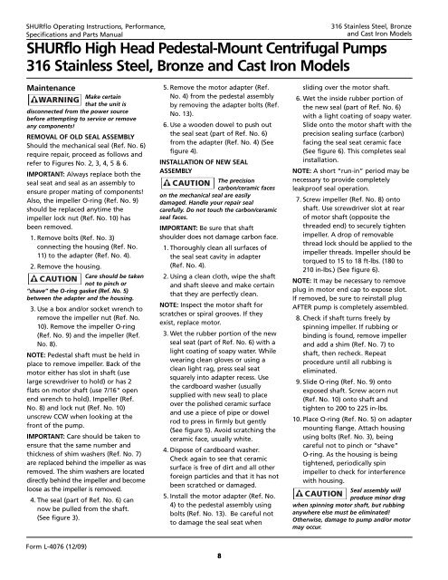
<strong>SHURflo</strong> Operating Instructions, Performance,Specifications and Parts Manual316 Stainless Steel, Bronzeand Cast Iron Models<strong>SHURflo</strong> <strong>High</strong> <strong>Head</strong> <strong>Pedestal</strong>-<strong>Mount</strong> <strong>Centrifugal</strong> <strong>Pumps</strong>316 Stainless Steel, Bronze and Cast Iron ModelsMaintenanceMake certainthat the unit isdisconnected from the power sourcebefore attempting to service or removeany components!REMOVAL OF OLD SEAL ASSEMBLYShould the mechanical seal (Ref. No. 6)require repair, proceed as follows andrefer to Figures No. 2, 3, 4, 5 & 6.IMPORTANT: Always replace both theseal seat and seal as an assembly toensure proper mating of components!Also, the impeller O-ring (Ref. No. 9)should be replaced anytime theimpeller lock nut (Ref. No. 10) hasbeen removed.1. Remove bolts (Ref. No. 3)connecting the housing (Ref. No.11) to the adapter (Ref. No. 4).2. Remove the housing.Care should be takennot to pinch or”shave” the O-ring gasket (Ref. No. 5)between the adapter and the housing.3. Use a box and/or socket wrench toremove the impeller nut (Ref. No.10). Remove the impeller O-ring(Ref. No. 9) and the impeller (Ref.No. 8).NOTE: <strong>Pedestal</strong> shaft must be held inplace to remove impeller. Back of themotor either has slot in shaft (uselarge screwdriver to hold) or has 2flats on motor shaft (use 7/16" openend wrench to hold). Impeller (Ref.No. 8) and lock nut (Ref. No. 10)unscrew CCW when looking at thefront of the pump.IMPORTANT: Care should be taken toensure that the same number andthickness of shim washers (Ref. No. 7)are replaced behind the impeller as wasremoved. The shim washers are locateddirectly behind the impeller and becomeloose as the impeller is removed.4. The seal (part of Ref. No. 6) cannow be pulled from the shaft.(See figure 3).5. Remove the motor adapter (Ref.No. 4) from the pedestal assemblyby removing the adapter bolts (Ref.No. 13).6. Use a wooden dowel to push outthe seal seat (part of Ref. No. 6)from the adapter (Ref. No. 4) (Seefigure 4).INSTALLATION OF NEW SEALASSEMBLYThe precisioncarbon/ceramic faceson the mechanical seal are easilydamaged. Handle your repair sealcarefully. Do not touch the carbon/ceramicseal faces.IMPORTANT: Be sure that shaftshoulder does not damage carbon face.1. Thoroughly clean all surfaces ofthe seal seat cavity in adapter(Ref. No. 4).2. Using a clean cloth, wipe the shaftand shaft sleeve and make certainthat they are perfectly clean.NOTE: Inspect the motor shaft forscratches or spiral grooves. If theyexist, replace motor.3. Wet the rubber portion of the newseal seat (part of Ref. No. 6) with alight coating of soapy water. Whilewearing clean gloves or using aclean light rag, press seal seatsquarely into adapter recess. Usethe cardboard washer (usuallysupplied with new seal) to placeover the polished ceramic surfaceand use a piece of pipe or dowelrod to press in firmly but gently(See figure 5). Avoid scratching theceramic face, usually white.4. Dispose of cardboard washer.Check again to see that ceramicsurface is free of dirt and all otherforeign particles and that it has notbeen scratched or damaged.5. Install the motor adapter (Ref. No.4) to the pedestal assembly usingbolts (Ref. No. 13). Be careful notto damage the seal seat whensliding over the motor shaft.6. Wet the inside rubber portion ofthe new seal (part of Ref. No. 6)with a light coating of soapy water.Slide onto the motor shaft with theprecision sealing surface (carbon)facing the seal seat ceramic face(See figure 6). This completes sealinstallation.NOTE: A short “run-in” period may benecessary to provide completelyleakproof seal operation.7. Screw impeller (Ref. No. 8) ontoshaft. Use screwdriver slot at rearof motor shaft (opposite thethreaded end) to securely tightenimpeller. A drop of removablethread lock should be applied to theimpeller threads. Impeller should betorqued to 15 to 18 ft-lbs. (180 to210 in-lbs.) (See figure 6).NOTE: It may be necessary to removeplug in motor end cap to expose slot.If removed, be sure to reinstall plugAFTER pump is completely assembled.8. Check if shaft turns freely byspinning impeller. If rubbing orbinding is found, remove impellerand add a shim (Ref. No. 7) toshaft, then recheck. Repeatprocedure until all rubbing iseliminated.9. Slide O-ring (Ref. No. 9) ontoexposed shaft. Screw acorn nut(Ref. No. 10) onto shaft andtighten to 200 to 225 in-lbs.10. Place O-ring (Ref. No. 5) on adaptermounting flange. Attach housingusing bolts (Ref. No. 3), beingcareful not to pinch or “shave”O-ring. As the housing is beingtightened, periodically spinimpeller to check for interferencewith housing.Seal assembly willproduce minor dragwhen spinning motor shaft, but rubbinganywhere else must be eliminated!Otherwise, damage to pump and/or motormay occur.Form L-4076 (12/09)8


