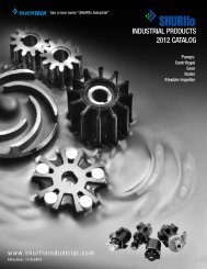
L-4088 - SHURflo Industrial
L-4088 - SHURflo Industrial
L-4088 - SHURflo Industrial

Create successful ePaper yourself
Turn your PDF publications into a flip-book with our unique Google optimized e-Paper software.
<strong>SHURflo</strong> Operating Instructions, Performance,Specifications and Parts Manual<strong>SHURflo</strong> 316 Stainless Steel RotaryPedestal External Gear PumpsModel Ordering Codes and OptionsViton Models GPSV2, GPSV4 and GPSV6Teflon ® Models GPST2, GPST4 and GPST6Example Model: GPSV2 (will require 3/4 HP ODP motor with >1.15 Service Factor*)(motor not supplied with pedestal pump)(1) (2) (3) (4)GP S V 21st 2nd 3rd 4thMounting Material Seal Gear**(Mech) Size: PortsGP: GearPedestalS: 316StainlessSteelV: VitonT: Teflon2: 3/8"4: 1/2"6: 1"NOTE: Not all order code combinations (configurations) are standard models available fromthe manufacturer. Custom model configurations may require ordering standard componentsand/or optional parts that will need to be assembled by the customer.Manufacturer reserves the right to change model order codes, standard models, specifications,and performance without notification.(*) ODP motors have > 1.15 service factors. Due to service factor, it is recommended TEFCmotors are oversized by one HP increment.Pedestal Pumps are not supplied with a motor.(**) Gears are made of Ryton PPS (Polyphenylene Sulfide).Maximum motor speed is 1725 RPM.Form L-<strong>4088</strong> (12/09)2
<strong>SHURflo</strong> Operating Instructions, Performance,Specifications and Parts ManualViton Models GPSV2, GPSV4 and GPSV6Teflon ® Models GPST2, GPST4 and GPST6Performance (with Oil)Viton Teflon GPM Pumping 10 Wt. Oil at 70° F (500 SSU)Pump Pump *Port Max. Input Pump Suction** Free Flow 25 PSI 50 PSI 75 PSI 100 PSI 125 PSIModels Models Size Torque in.-lbs. RPM Lift (ft) GPM HP GPM HP GPM HP GPM HP GPM HP GPM HP{{{45 900 1.5 2.5 1/4 2.5 1/4 2.4 1/4 2.3 1/4 2.1 1/4 1.8 1/3GPSV2 GPST2 3/8" 45 1200 2.2 3.3 1/4 3.3 1/4 3.2 1/4 3.1 1/3 2.9 1/3 2.6 1/245 1725 3.5 4.8 1/4 4.8 1/3 4.7 1/2 4.6 1/2 4.4 3/4 4.1 3/490 900 5.1 5.6 1/3 5.5 1/3 5.4 1/2 5.3 3/4 5 1 4.5 1GPSV4 GPST4 1/2" 90 1200 6.7 7.5 1/3 7.4 1/2 7.3 3/4 7.2 1 6.9 1 6.4 1 1 ⁄290 1725 12.3 10.8 1/2 10.7 3/4 10.6 3/4 10.5 1 10.2 1 1 ⁄2 9.7 1 1 ⁄2160 900 8.1 12.6 1/2 12.5 3/4 12.3 1 12.1 1 11.7 1 1 ⁄2 11.1 1 1 ⁄2GPSV6 GPST6 1" 160 1200 11.7 16.7 3/4 16.6 1 16.4 1 1 ⁄2 16.2 1 1 ⁄2 15.8 2 15.2 2160 1725 19.5 24.8 3/4 24.7 1 24.5 1 1 ⁄2 24.3 2 23.9 3 23.3 3Test data taken on SAE 10 wt oil at 70° F (500 SSU).Performance in water will decrease by about 10%, and HP required will also be reduced by 10% (see the chart below).Pump performance when pump is new. As pump wears, the performance will decrease.(*) Female NPT inlet and outlet (in inches).(**) Suction lift requires wetted gears and primed seal chamber.NOTES: Max. PSI = 125Max. Viscosity = 500 SSU at 1725 RPM with standard spur gearsMax. RPM = 1725Max. Specific Gravity = 1.1 at 125 PSI, up to 1.6 at lower PSI & viscosity.Max. Input Torque = See chart above.Reverse Rotation = Pumps can be run in reverse rotation.The pump relationship between volume (GPM), pressure (PSI), speed (RPM) and horsepower is shown on performance chart in Shurflo MotorManual form L-4082. When pumping a more viscous liquid, a slower speed, a larger pipe size pump, and possibly a larger motor should be selected.Manufacturer reserves the right to change performance without notification.Performance (with Water)Viton Teflon GPM Pumping Water at 90° F (31 SSU)Pump Pump *Port Max. Input Pump Suction** Free Flow 25 PSI 50 PSI 75 PSI 100 PSI 125 PSIModels Models Size Torque in.-lbs. RPM Lift (ft) GPM HP GPM HP GPM HP GPM HP GPM HP GPM HP{{{45 900 1.2 2.4 1/4 2.3 1/4 2.1 1/4 1.8 1/4 1.5 1/3 1.1 1/3GPSV2 GPST2 3/8" 45 1200 1.8 3.2 1/4 3.1 1/4 2.9 1/3 2.6 1/3 2.3 1/2 1.9 1/245 1725 3.0 4.6 1/3 4.5 1/2 4.2 1/2 4.0 1/2 3.7 3/4 3.3 3/490 900 4.5 5.5 1/4 5.1 1/4 4.5 1/3 4.1 1/3 3.7 1/2 3.1 1/2GPSV4 GPST4 1/2" 90 1200 6.0 7.3 1/3 7.0 1/3 6.3 1/2 5.9 1/2 5.5 3/4 4.9 3/490 1725 11.0 10.5 1/2 10.2 1/2 9.5 3/4 9.1 3/4 8.7 1 8.1 1160 900 7.0 12.6 1/2 12.0 3/4 10.9 3/4 10.1 1 9.1 1 1 ⁄2 8.1 2GPSV6 GPST6 1" 160 1200 10.0 16.7 3/4 16.1 3/4 15.0 1 14.2 1 1 ⁄2 13.2 2 12.2 2160 1725 17.0 24.0 1 23.4 1 22.3 1 1 ⁄2 21.5 2 20.5 3 19.5 3Test data taken with water at 90° F (31 SSU).Pump performance when pump is new. As pump wears, the performance will decrease.(*) Female NPT inlet and outlet (in inches).(**) Suction lift requires wetted gears and primed seal chamber.NOTES: Max. PSI = 125Max. Viscosity = 500 SSU at 1725 RPM with standard spur gearsMax. RPM = 1725Max. Specific Gravity = 1.1 at 125 PSI, up to 1.6 at lower PSI & viscosity.Max. Input Torque = See chart above.Reverse Rotation = Pumps can be run in reverse rotation.The pump relationship between volume (GPM), pressure (PSI), speed (RPM) and horsepower is shown on performance chart in Shurflo MotorManual form L-4082. When pumping a more viscous liquid, a slower speed, a larger pipe size pump, and possibly a larger motor should be selected.Manufacturer reserves the right to change performance without notification.Form L-<strong>4088</strong> (12/09)3
<strong>SHURflo</strong> Operating Instructions, Performance,Specifications and Parts Manual<strong>SHURflo</strong> 316 Stainless Steel RotaryPedestal External Gear PumpsSpecificationsViton Models GPSV2, GPSV4 and GPSV6Teflon ® Models GPST2, GPST4 and GPST6PUMP CONSTRUCTION (Wet End)NPTShaft,Inlet & Pump Body & Keys ShippingMax. Outlet Shaft Motor Bushing Cover Gear & Gasket O-Rings WeightModel RPM Port Size Adapter Material Castings Material Clip Material & Seals* (lbs.)316 SS Models with VitonGPSV2 1725 3/8" 1/2 Keyed CI CG 316 SS Ryton PPS 316 SS Graphoil Viton 7.1GPSV4 1725 1/2" 5/8 Keyed CI CG 316 SS Ryton PPS 316 SS Graphoil Viton 9.0GPSV6 1725 1" 3/4 Keyed CI CG 316 SS Ryton PPS 316 SS Graphoil Viton 11.8316 SS Models with Teflon ®GPST2 1725 3/8" 1/2 Keyed CI CG 316 SS Ryton PPS 316 SS Graphoil Teflon ® 7.1GPST4 1725 1/2" 5/8 Keyed CI CG 316 SS Ryton PPS 316 SS Graphoil Teflon ® 9.0GPST6 1725 1" 3/4 Keyed CI CG 316 SS Ryton PPS 316 SS Graphoil Teflon ® 11.8NOTE:(*) Standard Shaft Seals have carbon on ceramic faces and 316 SS components.Manufacturer reserves the right to change specifications without notification.SS = Stainless SteelCI = Cast IronCG = Carbon GraphiteRyton = PPS (Polyphenylene Sulfide)Form L-<strong>4088</strong> (12/09)4
<strong>SHURflo</strong> Operating Instructions, Performance,Specifications and Parts ManualViton Models GPSV2, GPSV4 and GPSV6Teflon ® Models GPST2, GPST4 and GPST6DimensionsFigure 1Port Shaft Dimensions (in inches)Model No. A* B** C* D E F G H I J K L M N O P Q RGPSV2, GPST2 3/8 1/2 1/8 5.39 3.85 8.18 9/32 2.15 1.25 2.25 3.00 4.21 0.25 3.25 2.80 0.81 0.60 1.75GPSV4, GPST4 1/2 5/8 1/8 6.54 4.72 9.32 13/32 2.40 1.44 2.88 3.50 4.65 0.28 3.5 3.15 0.75 0.70 1.87GPSV6, GPST6 1 3/4 1/8 7.82 5.66 11.38 13/32 2.94 1.82 3.32 4.40 5.83 0.30 4.18 3.94 1.125 1.035 2.25(*) Standard NPT (female) pipe thread inlet and outlet (in inches).(**) Shaft is slotted for key.NOTE: All dimensions have a tolerance of (+ or -) 1/8".Manufacturer reserves the right to change dimensions without notification.Form L-<strong>4088</strong> (12/09)5
<strong>SHURflo</strong> Operating Instructions, Performance,Specifications and Parts Manual<strong>SHURflo</strong> 316 Stainless Steel RotaryPedestal External Gear PumpsGear Identification and Dimension ChartViton Models GPSV2, GPSV4 and GPSV6Teflon ® Models GPST2, GPST4 and GPST6Gear Part Numbers and Dimensions (in inches)Ryton = PPS (Polyphenylene Sulfide)NOTE: Manufacturer reserves the right to change dimensions without notification.Figure 2 - Gear Identification and Dimension ChartForm L-<strong>4088</strong> (12/09)6
<strong>SHURflo</strong> Operating Instructions, Performance,Specifications and Parts ManualViton Models GPSV2, GPSV4 and GPSV6Teflon ® Models GPST2, GPST4 and GPST6Check motor.It may be equippedwith an automatic resetting thermalprotector and may restart unexpectedly(see specifications chart). Protector trippingis an indication of motor overloading as aresult of operating the pump at too high apressure (over 125 PSI), too high of viscosity,too high of specific gravity, excessively highor low voltage, inadequate wiring, incorrectmotor connections, too small a motor(sized incorrectly, not enough HP), or adefective motor or pump.Do not handle pump with wet handsor when standing in water. Failure tofollow the General Safety Informationand all warnings could result in fatalelectrical shock!InstallationIMPORTANT: In any installations whereproperty damage and/or personalinjury can occur when the pump isnot operating due to power outages,discharge line freezing, or any otherreason, a back-up system(s) and/orwarning system(s) should be used.In order to safely use this product,familiarize yourself with this pump andalso with the liquid (chemical, etc.) thatis going to be pumped through the unit.This pump is not suitable for manyliquids.1. Locate the pump as close to theliquid source as possible, makingthe suction line as short and directas possible.PIPINGSUCTION2. Avoid excessive lengths or number offittings and bends in the suction line.3. Attach suction line to suction inlet(See Figure 1 for proper rotation).4. It is recommended that same sizepipe as pump ports be used or, incases requiring lengthy piping, thenext larger size pipe be used.5. If suction lift is greater than what isindicated in the performance chart,attach a foot valve below liquidlevel at end of suction line toensure positive priming. Also note:If fluid specific gravity is greaterthan 1.4 or viscosity greaterthan 500 SSU, a foot valve is alsorecommended.NOTE: If a foot valve (or check valve) isnot used in the suction line, it may benecessary to refill the pump every timethe unit is stopped and you wish to restartthe pump. This depends on the length oftime between starts and whether or notthe gears are wet enough to close cavitiesto affect a prime.6. If solid contaminates are suspectedin a liquid, place a filter in thesuction line.7. Be certain all suction piping connectionsare airtight.NOTE: Assure airtight pipe connectionswith the use of a pipe joint sealant.DISCHARGE8. Attach discharge piping to thedischarge outlet.Support pump andpiping during assemblyand after installation. Failure to do so maycause piping to break, pump to fail, motorbearing failures, etc., all of whichcan result in property damage and/orpersonal injury.NOTE: Should the pump need to beself-draining, the pump head should bemounted in the vertical position withthe suction port facing down. Whenpumping high viscosity fluids, the verticalposition can be used with the suctionport facing up and the pumpmounted under the source. Increasingthe suction pipe size andeliminating bends and elbows alsoassists in pumping high viscosity fluids.Max. viscosity is 500 SSU at 1725 RPM.9. If a shut-off valve or handgun isrequired in discharge line, providea pressure relief valve for pumpprotection.Shutting offdischarge withoutproviding pressure relief can cause extremeoverpressure which can result in pumpand/or motor failure. Do not exceed 125 PSIpump or system pressure.10. Operation under shut-off dischargeconditions will overheat anddamage pump.NOTE: Globe valve or other restrictivevalves should not be used as shut-offmechanism as they are restrictive innature and will seriously affect pumpperformance.11. After all piping and controls (notsupplied with unit) have beeninstalled, unit is ready for operation.OperationDo not run pumpdry, as permanentdamage to the pump gears, seal, andbearings will result. Suction pressure shouldnever be greater than thedischarge pressure.1. All pumps must be primed beforestart-up and the seal chamber needsto be filled (See Figure 3). Neveroperate a pump unless it is securedto a solid foundation and all safetyshields are installed.Remove plug and fill seal chamberwith fluid and reinstall plugFigure 3 - Prime PlugUpon start-up, maintain a minimumof 15 PSI (1 BAR) operating pressureon the pump. This will allow anyremaining air to be driven from theForm L-<strong>4088</strong> (12/09)7
<strong>SHURflo</strong> Operating Instructions, Performance,Specifications and Parts Manual<strong>SHURflo</strong> 316 Stainless Steel RotaryPedestal External Gear PumpsViton Models GPSV2, GPSV4 and GPSV6Teflon ® Models GPST2, GPST4 and GPST6Operation (Continued)seal chamber and will ensure liquidcirculation to the mechanical seal.2. Gear pumps are built to very closetolerances and this tolerance mustnot be altered. The liquids must,therefore, be free of all abrasives.Sand, silt, wettable powders, etc.must be avoided.3. When pumping a more viscous(beyond 500 SSU) liquid; a slowerspeed, a larger pipe size pump,and possibly a larger motor shouldbe selected.NOTE: See performance chart for Max.Torque.4. Recheck motor and pump rotation.Pump rotation is by-directional(See Figure 1).PRESSURE RELIEF VALVE5. Standard models do not include apressure relief valve. If discharge isgoing to be shut off, an externalpressure relief valve should beinstalled.GEAR PUMP GASKET ADJUSTMENTFOR TEMPERATURE (see Appendix 1)6. For operation in fluid temperaturesabove 120° F, stainless steel pumpmodels must have the gasket thicknessadjusted. Use Appendix 1 toidentify pump, temperature andgasket recommendations for adjustingthe cover clearance prior tooperation in elevated temperaturesor viscosities above 500 SSU.Failure to adjust pumpcover clearances foroperating temperatures above 120° F. willresult in severe pump and/or motor damage.NOTE: When pumping fluids of highviscosity (>500 ssu), the required torqueand HP can be reduced by adding agasket for increased gear clearance.DRIVE CONNECTIONSNOTE: Pedestal Gear Pumps will operateequally well in either direction (SeeFigure 1). When looking at the pumpdrive shaft end and rotating the shaftclockwise, the discharge port is on theright-hand side. When turning counterclockwise,the discharge port is on theleft-hand side.DIRECT COUPLING DRIVESNever use a rigid coupling between thepump and the motor. Some degree offlexibility must be allowed at thecoupling to avoid excessive side loadingof the motor and pump bearings. Anyflexible coupling rated for the horsepowerload and speed is satisfactory.Care should be taken that the pumpand motor shaft are in alignment.Misalignment will cause unnecessaryloads on the pump and motor bearings.NOTE: Unit is not recommended fordirect drive by engine (gasoline ordiesel). If engine drive is desired, a “V”-belt arrangement is recommended toreduce torque pulsations on the pump.PULLEY DRIVEIn some cases, a reduction in pumpspeed is essential. This may be accomplishedthrough a belt and pulley drive.Bear in mind, however, that belt tensionadds a side thrust to the pump driveshaft which results in extra bearingloading and wear with resulting shortenedpump life. Adjust belt tension tobelt manufacturers’ recommendations.7. For pulley-driven pumps, a single1/2 (A or 4L section) “V” belt issatisfactory for drive sizes andspeeds up to 1 HP, 3450 RPM. Forlarger drive sizes, double “V” beltsare recommended. Maximum pumpRPM is 1725.8. Install safety guards, shield, etc.,around all moving parts.Failure to installproper safety guards,shields, etc. can result in property damageand/or personal injury. Follow all electricaland safety codes, as well as United StatesNational Electrical Code (NEC) andOccupational Safety and Health Act (OSHA).9. When using an electric motor, makenecessary electrical connections forthe voltage outlet supply anddouble-check all connections.Check power connections for propervoltage. (Refer to wiring diagramon motor nameplate or inside theterminal box for the properconnections.) See General SafetyInformation.IMPORTANT: Electrical circuit must beproperly fused.MECHANICAL SEAL FLUSHINSTALLATION OPTIONS10. These stainless steel pumps areequipped with mechanical seals andhave been designed with flush portsbecause mechanical seals requirecooling lubrication for long life.a. For fluids with viscosities less than2000 SSU, a flush is not necessary,but the seal cavity must be prefilledwith either the operatingfluid or a neutral fluid. This is toensure seal cooling and lubricationduring start-up (See Figure 3).Failure to provideinitial seal prime canresult in the mechanical seal overheatingwith resulting repair costs.b. For high viscosity fluids, a flushwill be necessary. The seal mustbe cooled and lubricated by afluid. In the case of high viscosityfluids, due to the precision clearancesbetween the gear teeth andthe stainless steel body, highlyviscous fluids will not be able toadequately relieve the air in theseal cavity on start-up. The dryrunning of a mechanical sealForm L-<strong>4088</strong> (12/09)8
<strong>SHURflo</strong> Operating Instructions, Performance,Specifications and Parts ManualViton Models GPSV2, GPSV4 and GPSV6Teflon ® Models GPST2, GPST4 and GPST6PumpSuctionDischargeSeal CavityFigure 4 - External FlushFlow MeterNeedle ValveCheck ValvePumpSuctionDischargeSeal CavityFigure 5 - Internal Flushwill cause rapid failure. A flushmust be provided for fluids with aviscosity of greater than 2000 SSU.Pumping fluids withviscosities greater than2000 SSU requires flushing the seal chamberduring operation, otherwise seal damagewill occur.EXTERNAL FLUSHAn external flush system is typicallyrecommended for applications wherecrystallization build-up on the seal ispossible. Some dilution of the workingmaterial must be acceptable to use anexternal flush system.The external flush system (See Figure 4for typical installation) is commonlyused with liquids where city water canFlow Meterbe used as the neutral flush fluid. Citywater is taken from an external sourcesuch as a tap, hose, or special plumbingfixture and is regulated into the sealcavity by means of a needle valve andflow meter. Use of an anti-siphon checkvalve is required.It is essential that ananti-siphon checkvalve be installed between the pump andthe city water supply to prevent any backflow from possibly contaminating the citywater supply. Failure to do so could result incontamination of the water supply with consequentialdamages. Manufacturer assumesno responsibility for failure of user in notproviding safeguards to city water systems.Step 1: Locate appropriate city watersupply and install anti-siphon checkvalve.Needle ValveStep 2: Use appropriate pipe nipple toreduce piping to 1/8”.Step 3: Install appropriate needle valveand flow meter.Step 4: Connect piping to one of threeavailable seal flush ports on pump.Step 5: Adjust needle valve to achievedesired flow to seal cavity (recommended1 to 3 GPH).INTERNAL FLUSHSimilar to above but internal supply(See Figure 5 for typical installation).Typically recommended for high viscosityapplications ensuring lubrication tothe mechanical seal.Form L-<strong>4088</strong> (12/09)9
<strong>SHURflo</strong> Operating Instructions, Performance,Specifications and Parts Manual<strong>SHURflo</strong> 316 Stainless Steel RotaryPedestal External Gear PumpsOperation (Continued)In an internal flush system, the fluid istaken from the discharge and regulatedfrom 1 to 3 GPH (Gallons Per Hour) tothe seal cavity by means of a flowmeter and needle valve.Step 1: Select a T pipe coupling that isconsistent with discharge pipe size andmaterial. Couple to discharge piping.Step 2: From this coupling, attach aneedle valve with appropriate nipple,reducing to 1/8” pipe or tube. Installappropriate flow meter.Step 3: Connect 1/8” pipe or tube toone of three available seal cavity flushports.Step 4: Adjust needle valve to desiredflow into seal cavity (recommended1 to 3 GPH).For alternate flushsystems for hazardousfluid applications, hot liquid transfer, andthose not addressed in this booklet, consulta qualified fluid handling specialist forassistance in specifying and installing flushsystems according to local, state and federalenvironmental laws.11. Unit is ready for operation.MaintenanceMake certain that thepower source isdisconnected before attempting to service ordisassemble any components!If the power disconnect is out of sight, lock itin the open position and tag to preventapplication of power.CLEANINGClean the suction line filter at regularintervals.ELECTRIC MOTOR (NOT SUPPLIED)Properly selected and installed, electricmotors are capable of operating foryears with minimal maintenance.Periodically clean dirt accumulationsfrom open-type motors, especially inand around vent openings, preferablyby vacuuming (avoid imbedding dirt inwindings). Oil and maintain as recommendedby motor manufacturer.GENERALCheck the pump to motor shaft alignmentat regular intervals.Periodically check that electrical connectionsare tight. Pump should be drainedif placed in an area that is subject toViton Models GPSV2, GPSV4 and GPSV6Teflon ® Models GPST2, GPST4 and GPST6freezing temperatures and should notbe operated until temperature permits.To store the pump, place a small quantityof light oil or some other storage preservativecompatible with your applicationin the pump and rotate the shaft veryslowly to work the oil throughout thegears and the body.PUMP REPAIRDISASSEMBLY(Refer to Figure 11 for ReferenceNumbers and Figures 6, 7, 8 & 9 fordetailed seal and shaft assemblies.)1. Gear Removala. Remove cover plate (Ref. No. 2)(held by eight screws) and gasket(Ref. No. 3) if needed. Gently tapcover plate with rubber mallet tofree it from dowel pins. Oncecover is removed, the idler shaftand gear assembly can be pulledout of pump body (Ref. No. 11).b. Remove the idler gear (Ref. No. 6)from the shaft (Ref. No. 7) byremoving retaining rings(Ref. No. 5), then slide gears offthe shaft end.Gear Pump BodyO-ringShaft, Seal,Bearing AssemblyRetainingRingShaftRetaining RingWasherMechanical SealSeal Seat RetainerRetaining RingBearingRetainingRingFigure 6 - Shaft, Seal and Bearing AssemblyFigure 7 - Shaft, Seal and Bearing Assembly (detail view)Form L-<strong>4088</strong> (12/09)10
<strong>SHURflo</strong> Operating Instructions, Performance,Specifications and Parts ManualViton Models GPSV2, GPSV4 and GPSV6Teflon ® Models GPST2, GPST4 and GPST6c. The drive gear (Ref. No. 6) canbe pulled out. Before drive shaft(Ref. No. 9) can be removedfrom body (Ref. No. 11), removewoodruff key (Ref. No. 8) bygently tapping key with drift pin.(Do not damage key or keywayupon removal.)2. From the drive shaft end of the gearpump, remove the internal snapring (Ref. No. 12) from the body(Ref. No. 11). The drive assembly,which consists of the drive shaft(Ref. No. 9), seal assembly (Ref. Nos.17 & 18), seat retainer (Ref. No. 15),bearing (Ref. No. 14) and retainingrings (Ref. No. 13), can now beremoved from the unit (See Figure6). Also remove the internal o-ring(Ref. No. 19) from the body.REASSEMBLY(Refer to Figure 11 for ReferenceNumbers and Figures 6, 7, 8 & 9 fordetailed seal and shaft assemblies.)1. Shaft/Seal Assemblya. Install inside o-ring (Ref. No. 19)into body (Ref. No. 11). Lubricatewith water.b. There are two possible types ofseals. One style, the seal is onepiece while the other style has aseal boot, spring and springretainer. The seal seats can alsobe of two styles; one has a rubberboot and the other has an o-ring.Identify which type you have(See Figure 8). (For the Teflonseal, see the following note andFigure 10.)c. Refer to assembling componentson drive shaft (See Figure 7).When installing the seal on theshaft, wet with water and becautious when sliding it intoposition. The spring retainingwasher and spring are behindthe seal with the carbon ceramicfacing towards the keyed end ofdrive shaft (See Figure 7).d. Press seal seat into the sealretainer (See Figure 9) usingwater as a lubricant. The whiteshiny ceramic face should be visibleafter pressing the seal intothe seal retainer. It is recommendedto use a cardboard washer orwood dowel when pushingthe seal seat into the seal seatretainer. Any scratches, dirt, orfingerprints on the carbon ceramicfaces will cause the seal to leak.The seal seat is stationary in thepump, while the seal on the shaftrotates, providing for the sealingsurface.NOTE: When installing the seat for theTeflon seal, an anti-rotation pin must beinstalled into the seat retainer. Theanti-rotation pin (Ref. No 20) is a smallspring pin which must be installed intothe seat retainer in the small hole.About 1/8” to 3/16” of the pin shouldbe exposed inside of the seat retainer(Figure 9). The seal seat is then installedinto the seat retainer.IMPORTANT! The notch on the back ofthe seat retainer must be aligned to theanti-rotation pin when pressing theseat into place.“C” Clips (4)Remove after set screwsare tight on shaftSet screws (2)Figure 10 - Teflon Seal and SeatCeramic Seatwith O-ringMechanical Seal withSeal, Spring & Retainer(three loose pieces)One-pieceMechanical Sealwith Thru BootNotch in seataligned with pinAnti-RotationSpring Pin(Teflon Seals Only)Seal Seat(Ref. 14)Polished Facealways goes againstCarbon Face of sealFigure 8 - Seal Types and Parts IdentificationCeramic Seatwith Rubber CupFigure 9 - Seal Seat and Retainer AssemblySeat Retainer(Ref. 15)Form L-<strong>4088</strong> (12/09)11
<strong>SHURflo</strong> Operating Instructions, Performance,Specifications and Parts Manual<strong>SHURflo</strong> 316 Stainless Steel RotaryPedestal External Gear PumpsMaintenance (Continued)NOTE: When installing the Teflon seal,the procedure is modified. The seatretainer/seal seat/anti-rotation pinassembly is then placed over the shaftassembly and against the ball bearing.The polished face of the ceramic shouldbe showing. The mechanical seal comeswith several “C” clips on either side(Figure 10).The purpose of these clips is to establishthe correct seal compression. These areremoved only in the very last step ofthe operation. Do not remove theseclips until the last step. Failure to dothis will prevent correct installation ofthe Teflon seal with resulting leakageand or immediate failure of the seal.Note that the working height of theTeflon seal is different than that ofeither the Viton or Buna-booted seals.As such, the seal will not align to or usethe retaining ring. Discard the retainingring (Ref. No. 13). that was behind thestandard seal that came with the pump.The mechanical seal is placed on theshaft with the polished carbon faceagainst the polished ceramic of theseat. Do not use any lubricants wheninstalling the seal other than very cleanwater. The use of lubricants can causeweeping of the mechanical seal Teflonwedges. Make sure that all of thesecomponents are installed tight againsteach other (ball bearing, seat retainerwith seat, and the mechanical seal).Tighten the set screws on the mechanicalseal so that it is tight to the shaft(See Figure 10). Now remove the “C”clips from the seal to actuate thesprings and spring tension on the sealface. The seal is now installed. Unlikethe “boot” seals in Viton and Buna, anexternal retaining ring (Ref. No. 13) isnot required to hold the seal. The setscrews accomplish that. The Teflonmechanical seal is shorter than thebooted seal. As such, it will not extendall of the way to the retaining ringgroove. This is normal.e. Slide the seal retainer and bearingonto the drive shaft andinstall retaining ring, holding thebearing and seal onto the shaft(See Figures 6 and 7).f. Slide the drive shaft assembly(Ref. Nos. 9, 13, 14, 15, 17 & 18)into the gear pump and securewith the internal retaining ring(Ref. No. 12). (Also see Figure 6.)2. Gear Installationa. Replace the woodruff key (Ref.No. 8) into the drive shaft (Ref.No. 9) using soft-jaw pliers, orprotect the shaft with rubberwhile pressing the key in place.Be sure that the key is level andthat the key and shaft are free ofburrs and scratches.b. The drive gear (Ref. No. 6) can bedropped in place and must befree to float on the shaft. Do notforce the drive gear onto theshaft.Viton Models GPSV2, GPSV4 and GPSV6Teflon ® Models GPST2, GPST4 and GPST6c. The idler gear (Ref. No. 6) isplaced on the idler shaft (Ref.No. 7) over the woodruff key andsecured by the two externalretaining rings (Ref. No. 5).d. Slide idler gear and shaft assemblyinto pump body (Ref. No. 11),rotating gear to get gears tomesh.e. Ensure that the gasket surfacesare clear of debris, and dry offsurfaces.Place new, clean and dry gasket(Ref. No. 3) on the pump body bysliding gasket over dowel pins.To identify the right thickness ofgasket to use, refer to Appendix 1.Any foreign materialor liquid on the gasketor the gasket surfaces will increase the spacebetween the gears and the cover, andsubstantially reduce pump performance.f. Slide cover (Ref. No. 2) over dowelpins (Ref. No 1). Replace andtighten cover screws. Alternatefrom top to bottom and side toside while tightening screws.Torque cover screws (SeeAppendix 1).g. Reinstall pump and install safetyshields and guards.h. All pumps must be primed beforestart-up and the seal chamberneeds to be filled (See Figure 3).Form L-<strong>4088</strong> (12/09)12
<strong>SHURflo</strong> Operating Instructions, Performance,Specifications and Parts Manual<strong>SHURflo</strong> 316 Stainless Steel RotaryPedestal External Gear PumpsRepair Parts ListViton Models GPSV2, GPSV4 and GPSV6Teflon ® Models GPST2, GPST4 and GPST6IncludedPart No. for Pump ModelRef. No. In Kit Description GPSV2 GPSV4 GPSV6 GPST2 GPST4 GPST6 Qty.1 Soc. Hd. Screw 19888 19888 19888 19888 19888 19888 82 Cover - 316 SS*** 21870S 21871S 21872S 21870S 21871S 21872S 13 1 Gasket - Graphoil 22115 22116 19931 22115 22116 19931 1Optional High Temperature Gasket Kit 24436 23956 23982 24436 23956 239824 Bushing - Carbon Graphite 21222 21223 21179 21222 21223 21179 35 1, 2, 3, 4 Ext. Ret. Ring 21094 12840 21063 21094 12840 21063 26 1, 2, 3, 4 Gear - Ryton PPS 13879 12764 13883 13879 12764 13883 27 2 Idler Shaft - 316 SS 21876 21877 21878 21876 21877 21878 18 1, 2, 3, 4 Woodruff Key - 316 SS 21301 12841 12841 21301 12841 12841 29 3, 4 Drive Shaft - 316 SS 22167 21874 22171 22167 21874 22171 110 3, 4 Square Key - 316 SS 21436 21437 21437 21436 21437 21437 111 Body - 316 SS*** 19747S 21114S 19753S 19747S 21114S 19753S 112 3, 4 Int. Ret. Ring - 316 SS 04303 04259 19942 04303 04259 19942 113 3, 4 Ext. Ret. Ring 21093 12582 15952 21093 12582 15952 314 3, 4 Ball Bearing 04306 04257 19988 04306 04257 19988 115 3, 4 Retainer - 316 SS 21969 21968 22144 21969 21968 22144 116 Pipe Plug - 316 SS 21059 21059 21059 21059 21059 21059 3*17/18 3 Mech Seal/Seal Seat (Standard) 24766S 24767S 24768S 24612S 24613S 24614S 1Optional 3 Mech Seal/Seal Seat (Viton) Std. Std. Std. 24766S 24767S 24768S 1**Optional 3 Mech Seal/Seal Seat (Teflon ® ) 24612S 24613S 24614S Std. Std. Std.Optional 4 Mech Seal/Seal Seat (Buna) 24604S 24605S 24606S 24604S 24605S 24606S19 3 O-Ring (Standard) 22173 22174 22343 22191 22192 22193 1Optional 3 O-Ring (Viton) Std. Std. Std. 22173 22174 22343 1Optional 3 O-Ring (Teflon ® ) 22191 22192 22193 Std. Std. Std.Optional 4 O-Ring (Buna) 21303 21913 23447 21303 21913 23447**20 Anti-Rotation Pin 22537 22537 22537 22537 22537 22537 121 Dowel Pin 21056 21056 21056 21056 21056 21056 13, 5, 6, 8 Kit 1 - Gear Repair Kit 22278 22279 22280 22278 22279 222805, 6, 7, 8 Kit 2 - Idler Shaft/Gear Assy. Kit 22437 22438 22439 22437 22438 224395, 6, 8, 9, 10, 12, Kit 3 - Dr. Shaft/Gear Assy. Kit 22441V 22444V 22447V 22441T 22444T 22447T13, 14, 15, 17/18, 19 (Viton or Teflon ® )5, 6, 8, 9, 10, 12, Kit 4 - Dr. Shaft/Gear Assy. Kit (Buna) 22441B 22444B 22447B 22441B 22444B 22447B13, 14, 15, 17/18, 19NOTE:For operating temperatures greater than 120° F. or high viscosities, gasket thickness must be adjusted.(*) Mech. seal and seat sold as set only (Ref. Nos. 17 & 18). Teflon ® and Viton seals consist of carbon ceramic faces with 316 SS components.Buna seals have 18-8 stainless steel components.(**) When ordering the Teflon ® seal, Anti-Rotation Pin is required (Ref. No. 20).(***) Body and cover supplied with carbon graphite bushings installed.When converting to a different seal/seat material, remember to order the o-ring (Ref. No. 19) of the same material.SS = Stainless SteelRyton = PPS (Polyphenylene Sulfide)Kits 2 - 4 do not ship with gaskets.Form L-<strong>4088</strong> (12/09)14
<strong>SHURflo</strong> Operating Instructions, Performance,Specifications and Parts ManualNotesForm L-<strong>4088</strong> (12/09)15
<strong>SHURflo</strong> Operating Instructions, Performance,Specifications and Parts ManualViton Models GPSV2, GPSV4 and GPSV6Teflon ® Models GPST2, GPST4 and GPST6Appendix 1 - Gear Pump Gasket Adjustment for TemperatureGear pump is factory assembled tooperate within a temperature range of70° – 120° F (20° – 50° C). For temperaturesoutside this range, please see thetable below for your series and portsize pump.NOTE: Always refer to the originalowner’s manual repair and maintenancesections on pump disassemblyand assembly for more detailedinstructions.NOTE: When pumping fluids of highviscosity (>500 SSU), the required torqueand HP can be reduced by adding agasket for increased gear clearance.Gasket Installation Instructions (referto assembly diagram below):1. Turn off power to pump, turn offinlet and outlet valves, and relievepressure in lines.2. Allow pump to cool.3. Remove cover screws (1), cover (2)and gasket (3). Be sure to markproper orientation of cover andpump body.4. Replace gaskets (3) per instructionslisted in table.5. Replace cover (2) and cover screws(1) according to orientationmarked in step 3.6. Tighten cover screws (1) insequence listed on diagram. Usetorque specifications listed in table.Stainless Steel Gear Pump SeriesKit PN NPT Port Size Temp Range Instructions Bolt Torque244362395623982Pumps with 3/8"portsPumps with 1/2"portsPumps with 1"portsUp to 120° F(50° C)120° F – 280° F(50° C – 138° C)Up to 120° F(50° C)120° F – 280° F(50° C – 138° C)Up to 70° F(20° C)70° F – 120° F(20° C – 50° C)120° F – 280° F(50° C – 138° C)Use standard graphoil gasket asshipped (0.010" thick)*Use optional thicker (0.015") graphoilgasketUse standard graphoil gasket asshipped (0.010" thick)*Use optional thicker (0.015") graphoilgasketUse optional thinner (0.010") graphoilgasketUse standard graphoil gasket asshipped (0.015" thick)*Use 2X optional thinner (for a total of0.020") graphoil gasket*Standard Set-up75 in.-lbs.(8.5 N-m)75 in.-lbs.(8.5 N-m)75 in.-lbs.(8.5 N-m)Gear PumpGasket InstallAssemblyBoltTighteningSequenceForm L-<strong>4088</strong> (12/09)Printed in USAFLOW TECHNOLOGIES GROUP5900 Katella Ave. • Cypress, CA 90630Phone: (800) 854-3218 • (562) 795-5200 • Fax: (562) 795-7554www.shurfloindustrial.com