Station controller m-Pro-400SE - Apex Tool
Station controller m-Pro-400SE - Apex Tool
Station controller m-Pro-400SE - Apex Tool

Create successful ePaper yourself
Turn your PDF publications into a flip-book with our unique Google optimized e-Paper software.
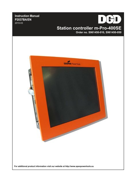
Instruction ManualP2037BA/EN2010-03<strong>Station</strong> <strong>controller</strong> m-<strong>Pro</strong>-<strong>400SE</strong>Order no. S961450-010, S961450-050For additional product information visit our website at http://www.apexpowertools.eu
Notes on this instruction manualThis instruction manual is the – translation of the original Instruction Manual –• It provides important instructions for safe and effective operation.• It describes the function and operation of the station <strong>controller</strong> m-<strong>Pro</strong>-<strong>400SE</strong>(hereinafter referred to simply as m-<strong>Pro</strong>-<strong>400SE</strong>).• It serves as a reference work for technical data and service intervals.• It points out options.Additional informationP2044PA <strong>Pro</strong>gramming manual of software for tightening <strong>controller</strong>, stationSymbols in the text:➔Identifies instructions to be followed.• Identifies lists.Symbosl in graphics:Identifies movement in a direction.Identifies function and force.Disclaimer:<strong>Apex</strong> <strong>Tool</strong> Group reserves the right to modify, supplement or improve this document or the product withoutprior notice. This document may not be reproduced in whole or in part in any way, shape or form, or copiedto another natural or machine-readable language or to a data carrier, whether electronic, mechanical, opticalor otherwise, without the express permission of <strong>Apex</strong> <strong>Tool</strong> Group.DGD is a trademark of the <strong>Apex</strong> <strong>Tool</strong> Group Division.2 P2037BA/EN 2010-03 en00b411_a.fm, 20.07.2011
4 P2037BA/EN 2010-03 P2037BA-EN_2010-03_m-<strong>Pro</strong>-<strong>400SE</strong>-HW_aIVZ.fm, 20.07.2011
Safety11 SafetyDo not operate the m-<strong>Pro</strong>-<strong>400SE</strong> unless you have carefully read and fully understood the following safetyinstructions and the instruction manual for your model.We do not claim that these safety notes are complete.Read and observe all applicable, general and local safety and accident prevention rules.1.1 SymbolsThe purpose of the following notes is to guarantee preservation of personal safety as well as to protect thestation <strong>controller</strong> m-<strong>Pro</strong>-<strong>400SE</strong> from damage.The symbols defined below highlight safety notes and warnings in this instruction manual, which alert tohazards endangering health and life of maintenance staff and causing property damage.DANGER!A symbol combined with the word DANGER warns of an impending health risk or risk of fatal injury to personnel.If this danger note is not adhered to, severest injury that may lead to the death of people, is the consequence.WARNING!A symbol combined with the word WARNING warns of a potentially dangerous situation for the health ofpersonnel, which, if not avoided, could result in death or serious injury.CAUTION!A symbol combined with the word CAUTION warns of a potentially harmful situation for the health of personnelor damage to property or the environment. If this warning is not observed, injuries, property or environmentaldamage may occur.ATTENTION!This sign warns of a possibly damaging situation.If the note is not adhered to, the product or parts of it may be damaged.NOTEThis symbol indicates a general instruction.General instructions include application tips and special useful information, but no warnings againstdangers.1.2 Safety instructionsThe station <strong>controller</strong> described in this instruction manual m-<strong>Pro</strong>-<strong>400SE</strong> was developed, manufactured, inspectedand documented according to the relevant safety standards. Therefore, the m-<strong>Pro</strong>-<strong>400SE</strong> does notnormally represent a danger to property or persons as long as the handling instructions and safety notesare adhered to during installation and first operation.• The company operating the product must make this instruction manual available to operators and mustensure that operators have read and understood it.• Do not attempt to repair possible faults on the m-<strong>Pro</strong>-<strong>400SE</strong> by yourself if you do not have the requiredknowledge!Inform the local repair center or your <strong>Apex</strong> <strong>Tool</strong> Group representative.• Follow a safety-conscious maintenance program which takes into account the local regulations for maintenanceand servicing in all phases of operation of the tightening <strong>controller</strong>.en01b411_bedingt.fm, 20.07.2011 P2037BA/EN 2010-03 5
1 Safety1.3 Intended useThe station <strong>controller</strong> m-<strong>Pro</strong>-<strong>400SE</strong> may be used only under the following conditions:• Industrial environment EMC limit class A (EN 55011).• Enclosed housing IP54.• Only ARCNET cables of types authorized by <strong>Apex</strong> <strong>Tool</strong> Group may be used.• Furthermore, only accessory parts authorized by <strong>Apex</strong> <strong>Tool</strong> Group may be used.• Unauthorized alterations, repairs and modifications are prohibited for reasons of safety and productliability.• The temperature inside the control cabinet may not exceed 50 °C (122°F).1.4 EMC measuresWARNING!• The filters and measures required to satisfy the EMC regulations are built into the design.• The enclosed metal housing provides substantial protection against irradiated and radiated interference.• The tool complies with the following EMC standards:Emissions- EN 55011:1998 + A1:1999 + A2:2002 Cl. ANoise immunity- EN 61000-4-2:1995 + A1:1998 + A2:2001- EN 61000-4-3:2002 + A2:2002- EN 61000-4-4:2004- EN 61000-4-5:1995 + A1:2002- EN 61000-4-6:1996 + A1:2001- EN 61000-4-8:1993 + A1:2001- EN 61000-4-11:2004- EN 61000-6-2: 2005Circuit feedback- EN 61000-3-2:2000 + A2:2005- EN 61000-3-3:1995 + A1:2001• This is a Class A device. The device may cause signal interference; in this case, the operator may berequired to implement suitable EMC measures.• Operation while the housing is open is prohibited, since the properties of the shielding would change andthe noise emission would increase.1.5 Operator training• The station <strong>controller</strong> m-<strong>Pro</strong>-<strong>400SE</strong> may only be commissioned by personnel who have specialized training(electrical/mechanical engineering).• The owner's operating and service personnel will be trained by qualified employees of <strong>Apex</strong> <strong>Tool</strong> Group.• A repair is only permitted by <strong>Apex</strong> <strong>Tool</strong> Group authorized personnel.6 P2037BA/EN 2010-03 en01b411_bedingt.fm, 20.07.2011
General information22 General information2.1 Overview<strong>Station</strong> <strong>controller</strong> … for m-<strong>Pro</strong>-<strong>400SE</strong> … for m-<strong>Pro</strong>-<strong>400SE</strong>without visualizationOrder number(without software) S961450-050 S961450-010Designation Controller SE, complete unit Controller SE, basicUsable softwareStandard, hand-guided application: S168850Standard, stationary application: S168850Standard, hand-held application: S168851Allowed range of numbers S168800 – S168899.For detailed information, please contact the <strong>Apex</strong> <strong>Tool</strong> Group Sales& Service Center.2.2 DescriptionThe station <strong>controller</strong> m-<strong>Pro</strong>-<strong>400SE</strong> includes the following functions:• Communication with resource control (for example, digital I/O, <strong>Pro</strong>fibus, Interbus, etc.).• Communication with computer networks (for example, Ethernet).• Communication with the TM tightening modules via ARCNET high-performance fieldbus.• Printer control• Tightening process control• Menu operation via touchscreen or additional mouse and/or external keyboard. 1)• Visualization via TFT color LCD monitor. 1)2.3 Field of application• The station <strong>controller</strong> m-<strong>Pro</strong>-<strong>400SE</strong> is used as the master computer, data concentrator and interfaceconcentrator in conjunction with the TM and TMH tightening modules.• Communication with the TM tightening modules takes place using an ARCNET serial high-performancefieldbus. A decentralized setup of the m-<strong>Pro</strong>-<strong>400SE</strong> and TMs at distances of up to 100 m can berealized.1) Only for S961450-050en02b411_bedingt.fm, 20.07.2011 P2037BA/EN 2010-03 7
2Generalinformation2.4 Ambient conditionsFeaturesDataAmbient temperature0 – 50 °C (32 – 122 °F)Storage temperature-20 – 60 °C (-4 – 140 °F)Cooling typeConvection (self-cooling)Relative humidity0 – 90 % non-condensingWorking height Up to 3000 m (9,842.5 ft) above sea level 1)Dust, dirtRequired enclosure (IP20, without installation)Exposure to sunlightCaution: causes an increase of temperature.<strong>Pro</strong>tect from direct sunlightOil, grease<strong>Pro</strong>tect the surface from contact with oils and greases.1) For use with TM modules: 1000 m (3,280.8 ft) above sea level2.5 Maintenance• Always replace the station <strong>controller</strong> m-<strong>Pro</strong>-<strong>400SE</strong> completely.• When the station <strong>controller</strong> is replaced for service, observe the software instruction manual.2.6 Transport and storage• Transport and store in suitable packaging only. If necessary, request packaging from <strong>Apex</strong> <strong>Tool</strong> Group.• The packaging can be recycled.• Check the m-<strong>Pro</strong>-<strong>400SE</strong> for any visible damage if the packaging is damaged. Inform the transportcompany, and, if applicable, <strong>Apex</strong> <strong>Tool</strong> Group.8 P2037BA/EN 2010-03 en02b411_bedingt.fm, 20.07.2011
Mechanical data33 Mechanical data3.1 S961450-05072_front.psdFeaturesDataHeight incl. front panel 250 mm (9.843”)Width incl. front panel 310 mm (12.205”)Depth 72 mm (2.835”)Weight3 kg (6.8 lbs)Mean time between failures (lamps)50,000 h<strong>Pro</strong>tection classIP20, without installation3.1.1 Installation guidelines• An enclosed housing made of sheet steel must be used.• Ensure that the EMC gasket to the enclosure functions properly. No insulating paint coat.• Do not block the housing openings above and below the m-<strong>Pro</strong>-<strong>400SE</strong> with components (cable ducts,etc.).Manufactured piece for door installationMounted to the housing on the integrated M4 threaded nuts.en03b411.fm, 20.07.2011 P2037BA/EN 2010-03 9
3Mechanicaldata3.2 S961450-0103.2.1 SizeFeaturesWeightService life, operating<strong>Pro</strong>tection classData1.2 kg (6.8 lbs)100,000 hIP20, without installation10 P2037BA/EN 2010-03 en03b411.fm, 20.07.2011
Mechanical data33.3 Connections for S961450-050 / S961450-010For technical data, see Technical data on page 19• Inputs / Outputs• USB version 1.1• Ethernet1, RJ45• ARCNet system bus• CAN bus (currently without function)• <strong>Pro</strong>fibus slave (DP)• RS232 for auxiliary equipment• Supply• CF cardATTENTION!Serial interfaces are not galvanically isolated. RS232-4_4 interface with 24 VDC on pin1 + 9: this interfacecan be used as the operating voltage for simple devices.This may cause damage to a standard modem or a PC connected via a null modem cable!Side, right S961450-050 Bottom S961450-010en03b411.fm, 20.07.2011 P2037BA/EN 2010-03 11
3Mechanicaldata• Ethernet 2,RJ45• LVDS monitor• VGA monitor• USB (currentlywithoutfunction)• Battery• PS/2 mouse• PS/2 keyboard–+–+Battery 1)Battery 1)1) Original equipment CR2025, alternative CR2032 (see Maintenance on page 15)Side, left S961450-050 Top S961450-050OptionalinterfaceEmpty CF slotNo automatic ejection12 P2037BA/EN 2010-03 en03b411.fm, 20.07.2011
Electrical Data44 Electrical Data4.1 System dataHardwareNonvolatilememoryInterfaces<strong>Pro</strong>cess interfaceSystem functionsBattery1 CF card for system and application with 256 MB (internal)ARCNET interface (system bus)4 serial data interfaces RS232 incl. printer (CON3)1 10/100 Base-T network interface on RJ451 PS/2 mouse/keyboard interface (CON4) 1)1 empty CF slot 1)1 LVDS display 1)1 VGA external monitor 1)2 Ethernet 1)1 USB1.1 1)I/O (process) 16-bit inputs/outputs 24 V opto-decoupled<strong>Pro</strong>fibus DP (slave)CAN bus (not enabled)RTC real-time clock with calendarWatchdog: voltage monitoringOriginal equipment:Varta CR2025: 170 mAh / 3.0 V or order No. 941555 Lithium batteryDisplay 1)Operating systemHMI (human-machineinterface)Data protection1) Only for S961450-050Alternative:Varta CR2032: 230 mAh / 3.0 V or order No. 933012 Lithium batteryLCD display, 1280x1024 pixels in color,Screen diagonal 305 mm (12")TouchscreenOS-9000 real-time operating system, bootable without mechanically movingdrives, no UPS requiredWindow-oriented, graphical user interface(S961450-010 only via PC via remote program)User access authorization, configurable (remote program)Parts to be dismountedOptional<strong>Pro</strong>fiNet, second <strong>Pro</strong>fibus port (more can be added on request)en04b411_bedingt.fm, 20.07.2011 P2037BA/EN 2010-03 13
4ElectricalData4.2 Power supplyATTENTION!Attempting to operate the station <strong>controller</strong> m-<strong>Pro</strong>-<strong>400SE</strong> at a voltage other than 24 VDC (e. g. 15 VAC /230 VAC) will result in immediate and irreparable total loss!Features Data DataOrder number S961450-050 S961450-010Nominal supply voltage 24 VDC 24 VDCNominal supply voltage limits 15 – 30 DC 15 – 30 DCRated supply current 0.83 A 0.4 AInternal fusing (slow blow) 2 A 2 APower loss (standby) 20 W 9 WCAUTION!The fuse on the power plug connector protects the lines in the m-<strong>Pro</strong>-<strong>400SE</strong> in the event of faults or anoversized external fuse.The fuse on the main board protects the conducting paths to the power adapter.➔ Internal fuses may only be changed by <strong>Apex</strong> <strong>Tool</strong> Group.14 P2037BA/EN 2010-03 en04b411_bedingt.fm, 20.07.2011
Maintenance55 MaintenanceInterval1 yearalternative2 yearsNOTEAs necessaryMeasuresBattery changeThe battery supplies the real-time clock with power and ensures data retention whenthe power supply is switched off.Type of battery – original equipment:Original equipment:Varta CR2025: 170 mAh / 3.0 V or order No. 941555 Lithium battery(typical duration for data retention = 1.4 years).Type of battery – recommended at maintenance:Varta CR2032: 230 mAh / 3.0 V or order No. 933012 Lithium battery(typical duration for data retention = 2.1 years)➔ Replace the battery when the station <strong>controller</strong> is switched off. For battery location,see Side, right S961450-050 on page 11.The battery change must be completed within 15 minutes. Exceeding this limit willresult in data loss of parameters, counter readings and time of day. Depending onsoftware and configuration in use, operation without battery can lead to disturbances(production downtimes). <strong>Apex</strong> <strong>Tool</strong> Group recommends to observe battery changeintervals.➔ Have the replacement battery ready. If in storage, do not short-circuit the batteryor exceed the storage time.➔ Wait for a pause in production.➔ <strong>Pro</strong>vide access to the station <strong>controller</strong> in the interior. Open the control cabinet orhousing.Caution: Do not cause a short-circuit or ground fault.➔ Remove the battery. Advice: use a pair of tweezers with insulated tips.➔ Insert the new battery. Polarity see Page 11.The positive pole can be identified by the larger contact area.➔ Carry out a test with production monitoring.Cleaning the touchscreen surface (S961450-050 only)➔ Set the screen to cleaning mode (test menu).➔ Clean the surface using a damp cloth, possibly with soap. After the programmedtime has elapsed, the screen switches back to normal mode.➔ Do not use any abrasive or solvent-containing cleaning agents.➔ Do not use hot cleaning equipment (steam cleaners) or high-pressure cleaners.➔ Do not exert excessive pressure on the glass plate.➔ Do not use hard or rough objects for cleaning.en04b411_bedingt.fm, 20.07.2011 P2037BA/EN 2010-03 15
5 Maintenance16 P2037BA/EN 2010-03 en04b411_bedingt.fm, 20.07.2011
Repair66 Repair6.1 Replacing S961450-050 in the housingCAUTION!CAUTION!Opening the housing holds specific risks.➔ The station <strong>controller</strong> m-<strong>Pro</strong>-<strong>400SE</strong> may be replaced by qualified personnel only.➔ Always replace the station <strong>controller</strong> m-<strong>Pro</strong>-<strong>400SE</strong> completely.Internal fuses protect the conducting paths in the device in the event of faults or an oversized external fuse.➔ Internal fuses may only be changed by <strong>Apex</strong> <strong>Tool</strong> Group.1. Set the main switch on the control cabinet to "OFF" or "0".2. Disconnect the power cable from the power supply.3. Disconnect the supply cable from the station <strong>controller</strong>.4. Disconnect all the connectors from the station <strong>controller</strong>.5. Loosen the PE connection.6. Unscrew the 8 screws on the mounting frame and unhook the station<strong>controller</strong> by pulling it forwards.Caution: support the station <strong>controller</strong> on the front. It may tilt forward.7. Hook in the new station <strong>controller</strong> and mount it to the mounting frame usingthe 8 screws.8. Reconnect the PE connection.9. Reconnect the station <strong>controller</strong> by following the reverse order of steps.NOTEBefore the system is switched on for the first time, connect all of the required components and check theconnections. Initially, do not connect the <strong>Pro</strong>fibus interface yet. First, check the parameters!10. Switch on and reconfigure parameters or accept the parameter settings from parameter backup.11. Check that the tightening <strong>controller</strong> functions properly. If necessary, also check surrounding functions,for example, if the tightening <strong>controller</strong> is integrated into the assembly process or connected to the line.en06b411.fm, 20.07.2011 P2037BA/EN 2010-03 17
6 Repair6.2 Replacing S961450-010 in the housingCAUTION!CAUTION!Opening the housing holds specific risks.➔ The station <strong>controller</strong> m-<strong>Pro</strong>-<strong>400SE</strong> may be replaced by qualified personnel only.➔ Always replace the station <strong>controller</strong> m-<strong>Pro</strong>-<strong>400SE</strong> completely.Internal fuses protect the conducting paths in the device in the event of faults or an oversized external fuse.➔ Internal fuses may only be changed by <strong>Apex</strong> <strong>Tool</strong> Group.1. Set the main switch on the control cabinet to "OFF" or "0".2. Disconnect the power cable from the power supply.3. Disconnect the supply cable from the station <strong>controller</strong>.4. Disconnect the ARCNet from the station <strong>controller</strong>.5. Disconnect all the connectors from the station <strong>controller</strong>.6. Unscrew the 2 screws on the mounting frame and unhook the station <strong>controller</strong>by pulling it forwards.7. Hook in the new station <strong>controller</strong> and mount it to the mounting frame usingthe 2 screws.8. Reconnect the station <strong>controller</strong> by following the reverse order of steps.NOTEBefore the system is switched on for the first time, connect all of the required components and check theconnections. Initially, do not connect the <strong>Pro</strong>fibus interface yet. First, check the parameters!9. Switch on and reconfigure parameters or accept the parameter settings from parameter backup.10. Check that the tightening <strong>controller</strong> functions properly. If necessary, also check surrounding functions,for example, if the tightening <strong>controller</strong> is integrated into the assembly process or connected to the line.18 P2037BA/EN 2010-03 en06b411.fm, 20.07.2011
Technical data77 Technical data7.1 ConnectionsAll connections are short-circuit proof.7.1.1 <strong>Station</strong> <strong>controller</strong> inputs/outputsThe required signal circuits are connected to these input/outputconnectors. The signal groups are not galvanically connected tothe power supply; galvanic isolation is required.Type: DIO16 (10 pole MICRO Combicon RM2.5 on processing unit)16-bit digital inputs/outputs, opto-isolated for 24V level / 0.5 APin DIO8-15 Pin DIO1-711 +24 VDC 1 +24 VDC12 I0 8 Bit 9 2 OK 0 Bit 113 OK 9 Bit 10 3 OK 1 Bit 214 OK 10 Bit 11 4 OK 2 Bit 315 OK 11 Bit 12 5 OK 3 Bit 416 OK 12 Bit 13 6 OK 4 Bit 517 OK 13 Bit 14 7 OK 5 Bit 618 OK 14 Bit 15 8 OK 6 Bit 719 OK 15 Bit 16 9 OK 7 Bit 820 GND 10 GNDen07b411_bedingt.fm, 20.07.2011 P2037BA/EN 2010-03 19
7TechnicaldataDigital input/outputThere are 16 available lines for 24V technology that can be programmed as inputs or outputs as desired.7.1.2 Ethernet RJ45Access is obtained internally or via cable bushings and connected directly to the processing unit.10/100 BASE-TPin Signal1 TPOP2 TPON3 TPIP4 nc5 nc6 TPIN7 nc8 nc20 P2037BA/EN 2010-03 en07b411_bedingt.fm, 20.07.2011
Technical data77.1.3 ARCNet system busAn ARCNet cable can be connected to this interface. The station <strong>controller</strong> has an integrated bus termination;therefore, no external termination is necessary.Access is obtained internally or via cable bushings and connected directly to the station <strong>controller</strong>.Type: 9-pole D-Sub pin with slide lockPin Signal1 PE2 nc3 DATA-B (ARC L)4 nc5 GND (ARCNet)6 +5 V (ARCNet) max. 100 mA7 nc8 DATA-A (ARC H)9 ncHousing PE shield connection7.1.4 CAN busType: 9-pole D-Sub pinPinSignal1 –2 CAN L3 CAN GND4 –5 –6 CAN GND2(close LB22 for this)7 CAN H89 CAN +5 VMax. 100 mA(close LB21 for this)en07b411_bedingt.fm, 20.07.2011 P2037BA/EN 2010-03 21
7Technicaldata7.1.5 <strong>Pro</strong>fibus slave (DP)The <strong>Pro</strong>fibus of a higher-level unit can be connected to this interface.Access is obtained internally or via cable bushings and connected directly to the processing unit.Type: 9-pole D-Sub plug with screw lockPin Signal1 CHGND2 nc3 IO+ (PRO H)4 nc5 GND6 +5 V max. 100 mA7 nc8 IO-(PRO L)9 ncHousing PE7.1.6 RS232 for auxiliary equipment• All outputs provide signals conforming to RS232.• The inputs allow voltages in the range from -15 V to +15 V.- Voltages < 0.8 V correspond to a zero.- Voltages > 2.4V are interpreted as a one.- Open inputs are preset to zero using a pulldown resistor.• The power supply pins are connected directly to the main board power supply.• A consumer should not require current of more than 500 mA.- Do not connect or tighten consumers during operation.Doing so may result in a system reset!A conventional barcode scanner, for example, can be connected to this interface (depending on thesoftware used). Access is obtained internally or via cable bushings and connected directly to the station<strong>controller</strong>.Type: 9-pole D-Sub pin with screw lockATTENTION!Serial interfaces are not galvanically isolated. RS232-4_4 interface with 24 VDC on pin1 + 9: this interfacecan be used as the operating voltage for simple devices.This may cause damage to a standard modem or a PC connected via a null modem cable!D-Sub pin RS232_1 RS232_2 RS232_3 RS232_41 – – – +24V2.500mA2 RxD PSC1_1 RxD PSC2_1 RxD PSC3_1 RxD PSC6_03 TxD PSC1_0 TxD PSC2_0 TxD PSC3_0 TxD PSC6_24 – – – –22 P2037BA/EN 2010-03 en07b411_bedingt.fm, 20.07.2011
Technical data7D-Sub pin RS232_1 RS232_2 RS232_3 RS232_45 GND GND GND GND6 – – – –7 RTS PSC1_2 RTS PSC2_2 RTS PSC3_2 RTS PSC6_38 CTS PSC1_3 CTS PSC2_3 CTS PSC3_3 CTS PSC6_19 – – – GND7.1.7 SupplyType: 4-pole Mini CombiconPHOENIX 1827 729Order No. S961397PinSignal1 +24V2 +24V3 GND4 GND7.1.8 LVDS monitorType: 15-pole D-SubPin Signal Pin Signal1 Touch X+ 14 LVDS TXOUT3+2 Touch Y+ 15 LVDS CLKOUT+3 Inverter /Panel On 1)16 LVDS TXOUT2+4 – GND 17 LVDS TXOUT1+5 LVDS TXOUT3- 18 LVDS TXOUT0+6 LVDS CLKOUT- 19 Touch Y-7 LVDS TXOUT2- 20 LVDS VCC Panel (Supply)8 LVDS TXOUT1- 21 Inverter 12_PANEL (Supply)9 LVDS TXOUT0- 22 Inverter /BL_ON_12 V10 Touch X- 23 – GND11 Touch 5A 24 Inverter BL_ON_5V12 Inverter 12_PANEL (Supply) 25 Inverter /BL_ON_5V13 Inverter DIMM (0 – 5V) 26 – GND1) Pull /PANEL_IO to GND for switching 12V_PANEL on.en07b411_bedingt.fm, 20.07.2011 P2037BA/EN 2010-03 23
7Technicaldata7.1.9 VGA monitorType: 15-pole D-Sub plug (HD type)PinSignal1 CRT_RT2 CRT_GN3 CRT_BL4 ID25 GND6 RT_GND7 GN_GND8 BL_GND9 –10 Sync GND11 ID012 ID1 / SDA13 CRT_HS14 CRT_VS15 SCL7.1.10 PS/2 mouseType: 6-pole Mini-DIN 6PinSignal1 Data2 –3 GNG4 VCC5 CLK6 –24 P2037BA/EN 2010-03 en07b411_bedingt.fm, 20.07.2011
Technical data77.1.11 PS/2 keyboardType: 6-pole Mini-DIN 6PinSignal1 –2 Data3 GNG4 VCC5 –6 CLK7.2 Storage access, portable memoryInterface m-<strong>Pro</strong>-<strong>400SE</strong>S961450-050m-<strong>Pro</strong>-<strong>400SE</strong>without visualizationS961450-010USB × ×Plug for compact flash × ×Empty compact flash slot(internal)× –7.2.1 USB (version 1.1)Not intended for serial devices or networking. Only USB sticks can be used here. Only a limited number ofproducts can be used for this embedded PC.USB sticks that can be usedDue to continuous product changes for commercial USB sticks, an advance performance test is required.We recommend <strong>Apex</strong> <strong>Tool</strong> Group stick, 1 GB, order No. S981007.7.2.2 Plug for compact flashFunction for S961450-050 for operating system and application. A CF card (internal) is required for operation.TypeSize1 128 MB2 256 MB3 512 MB4 Up to 2 GBen07b411_bedingt.fm, 20.07.2011 P2037BA/EN 2010-03 25
7Technicaldata7.3 MAC address7.3.1 Network accessThe MAC address (Media Access Control address) isthe hardware address of the station <strong>controller</strong>, which isused for unambiguous identification of the device inthe Ethernet network.The MAC address is on the rear side of the station<strong>controller</strong>, but can also be formed from the serial number.MAC = 00.12.91.50.xx.xx.xx.xx is determined by multiplying the last 4 digits of the serial number by 2 and converting the result intohexadecimal format. Example:Serial number A20035:0035 × 2 = 70 = 0x0046 ➔ MAC = 00.12.91.50.00.46Serial number A20080:0080 × 2 = 160 = 0x00A0 ➔ MAC = 00.12.91.50.00.A0A second Ethernet access is possible via the station <strong>controller</strong>'s graphic card. The MAC address of thisinterface is one higher than that of the first interface. Example:Serial number A20035:0035 × 2 = 70 = 0x0046 + 1 = 0x0047 ➔ MAC = 00.12.91.50.00.47Serial number A20080:0080 × 2 = 160 = 0x00A0 + 1 = 0x00A1 ➔ MAC = 00.12.91.50.00.A126 P2037BA/EN 2010-03 en07b411_bedingt.fm, 20.07.2011
Sales & Service CentersNote: All locations may not service all products. Please contact the nearest Sales & Service Center forthe appropriate facility to handle your service requirements.Dallas, TX Detroit, MI Houston, TX Lexington, SC<strong>Apex</strong> <strong>Tool</strong> Group <strong>Apex</strong> <strong>Tool</strong> Group <strong>Apex</strong> <strong>Tool</strong> Group <strong>Apex</strong> <strong>Tool</strong> GroupSales & Service Center Sales & Service Center Sales & Service Center 670 Industrial Drive1470 Post & Paddock 2630 Superior Court 6550 West Sam Houston Lexington, SC 29072Grand Prairie, TX 75050 Auburn Hills, MI 48326 Parkway North, Suite 200 Tel: 800-845-5629Tel: 972-641-9563 Tel: 248-391-3700 Houston, TX 77041 Tel: 803-359-1200Fax: 972-641-9674 Fax: 248-391-7824 Tel: 713-849-2364 Fax: 803-358-7681Fax: 713-849-2047Los Angeles, CA Seattle, WA York, PA Canada<strong>Apex</strong> <strong>Tool</strong> Group <strong>Apex</strong> <strong>Tool</strong> Group <strong>Apex</strong> <strong>Tool</strong> Group <strong>Apex</strong> <strong>Tool</strong> GroupSales & Service Center Sales & Service Center Sales & Service Center Sales & Service Center15503 Blackburn Avenue 2865 152nd Avenue N.E. 3990 East Market Street 5925 McLaughlin RoadNorwalk, CA 90650 Redmond, WA 98052 York, PA 17402 Mississauga, Ont. L5R 1B8Tel: 562-926-0810 Tel: 425-497-0476 Tel: 717-755-2933 CanadaFax: 562-802-1718 Fax: 425-497-0496 Fax: 717-757-5063 Tel: 905-501-4785Fax: 905-501-4786Germany England France China<strong>Apex</strong> <strong>Tool</strong> Group <strong>Apex</strong> <strong>Tool</strong> Group, LLC <strong>Apex</strong> <strong>Tool</strong> Group SAS Cooper (China) Co., Ltd.GmbH & Co. OHG Pit Hill Zone Industrielle a company ofIndustriestraße 1 Piccadilly BP 28 <strong>Apex</strong> <strong>Tool</strong> Group, LLCD-73463 Westhausen Tamworth 25 Avenue Maurice Chevalier 955 Sheng Li Road,Germany Staffordshire 77831 Ozoir-la-Ferrière Cedex Heqing Pudong, ShanghaiTel: +49 (0) 73 63/ 81-0 B78 2ER France China 201201Fax: +49 (0) 73 63/ 81-222 U.K. Tel: +33-1-64432200 Tel: +86-21-28994176Tel: +44 (0) 191 4197700 Fax: +33-1-64401717 Fax: +86-21-51118446Fax: +44 (0) 182 7874128MexicoBrazilCooper <strong>Tool</strong>sCooper <strong>Tool</strong>s Industrial Ltda.de México S.A. de C.V. a company ofa company of<strong>Apex</strong> <strong>Tool</strong> Group, LLC<strong>Apex</strong> <strong>Tool</strong> Group, LLC Av. Liberdade, 4055Vialidad El Pueblito #103 Zona Industrial - IporangaParque Industrial Querétaro 18087-170 Sorocaba, SP BrazilQuerétaro, QRO 76220 Tel: (011) 55 15 238 3929Tel: +52 (442) 211-3800 Fax: (011) 55 15 228 3260Fax: +52 (442) 103-0443<strong>Apex</strong> <strong>Tool</strong> Group, GmbH & Co. OHGIndustriestraße 1D-73463 WesthausenPhone: +49 (0) 73 63/ 81-0Fax: +49 (0) 73 63/ 81-222www.apexpowertools.eu