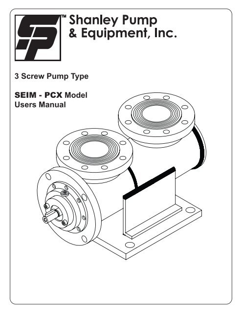
3 Screw Pump Type SEIM - PCX Model Users Manual
3 Screw Pump Type SEIM - PCX Model Users Manual
3 Screw Pump Type SEIM - PCX Model Users Manual
- No tags were found...

Create successful ePaper yourself
Turn your PDF publications into a flip-book with our unique Google optimized e-Paper software.
2.0 – Plant installation& roll out2.1 – Use suitable lifting gear2.2 – Open the packaging, lift the pump as little aspossible above ground and approach the installationpoint (fig. 1)2.3 – Connect the half-coupling after lightlylubricating the pump shaft (fig.2). Block using theblocker nut (fig.3).2.4 – Position the pump in line with the motorshaft and connect the motor connection flange tothe housing until the mounting bolts can be fullytightened (fig.4).2.5 – Remove the protective caps from pump. Fillthe pump with the fluid to be pumped in aspirationand output (fig.6). Wait a couple of minutes so thatthe fluid is distributed throughout the pump body. Addfluid until the inside of the pump is completely full.2.6 – Connect the aspiration and output pipes (fig.7).2.7 – Check the direction of rotation of the pump,pulse start the electric motor and observing thedirection of rotation of the motor fan or, where easier,of the shaft through an aperture to be effected in thehousing; the direction of rotation must comply withthe indications of the arrow on the identification plate.The first power up shouldbe limited to the time strictlynecessary to ensure that the direction ofrotation corresponds to the indications ofthe pump identification plate. This preventsthe partial or total damage of the pump incases of incorrect rotation.2.8 – Start the motor after having checked that allthe valves on the lines are fully open. At this pointthe pump begins to “draw” fluid.2.9 – Run the pump unloaded for a few minutesto facilitate the elimination of any air present inthe fluid. Then regulate the pressure to the valueforeseen for the system.pg 3
3.0 – Dismountingpump components3.1 Dismounting the seal3.1.1 Disconnect the pipes after emptying the pump.3.1.2 Disconnect the pump from the housing andextract the half-coupling after loosening the bolt.3.1.3 Hold the pump body in a vice with the jawscovered in soft material (®) to avoid damage to thedata on the information plate (fig.8).3.1.4 Remove the key from the central screw (fig.9).3.1.5 Remove the 4 bolts which connect themotor connection flange to the pump body (fig.9).3.1.6 Remove the motor connection flange withlight blows with a plastic hammer; the fixed sectionof the mechanical seal will remain within the motorconnection flange. Check the O-ring.3.1.7 Using a soft adjustable grips of appropriatediameter, extract the fixed section of the mechanicalseal from the connection flange (fig.10).3.1.8 Holding the central screw remove the rotarysection of the mechanical seal, rotating clockwiseand taking care not to touch the contact surface withyour hands (fig.11).3.2 Dismounting the jacket3.2.1 Unscrew the screws mating external racketdiameter (fig.12) and pull out complete pump inaxial direction according to arrow shown.pg 4
4.2 Mounting the mechanical seal4.2.1 Lubricate the O-ring and insert the fixed sectionof the mechanical seal to the motor connection flange.4.2.2 Position the pump vertical holding thecentral screw still. Fit the rotary section of themechanical seal rotating clockwise up to the elasticseal end run (fig.16).4.2.3 Clean the fixed and rotating sealingsurfaces of the mechanical seal with denaturedalcohol. Lubricate the O-ring and insert it into thesite of the motor connection flange..4.2.4 Insert the motor connection flange to thepump body and tighten, in alternate sequence, the 4mounting bolts.4.2.5 Insert the key into its’ site in the centralscrew using a plastic hammer.4.3 Mounting the external jacket.4.3.1 Lubricate Orings and Oring seats; insertagain axially complete pump inside jacket, fit thescrews and reassemble following back operationsdone in 3.2.5.0 – Section Drawingpg 6
6.0 – Problem descriptionand solvingWrong rotation directionEFFECTThe motor turns in the wrong direction as indicatedby the arrow on the identification plate.Throughput too lowEFFECT- The valves on the line are not fully open.- The maximum pressure valve is set with too low apressure value.- The filter is blocked or an obstacle in the oil flow line.Pressure too lowEFFECT- Pipe leakage- Output pressure is too low.- The maximum pressure valve is set to too low apressure setting.Motor starts badlyEFFECT- Pressure required from system too high.- Oil too cold- The motor set not deliver the power required.- the motor taring relay is too low.<strong>Pump</strong> noisy when operatingEFFECT- If the pump is noisy during operation, check if:-The pipe is too long or the section diameter of thepipe is too small.-The filter is blocked or the valve is closed inaspiration.-The aspiration pressure is elevated.-There is air in the system.-The motor-pump alignment is incorrect.-The pump is worn or damaged. Contact themanufacturer..POSSIBLE SOLUTIONSIn three phase motors, two electric phase connectionwires must be exchanged.POSSIBLE SOLUTIONS- Open the valves and restart the pump.- Loosen the regulation screw until it may be handturned and action the pump for a few minutes at nopressure. Then tighten the regulation screw to thesetting value desired.- Check the plant. Check that the obstacle has notentered the pump.POSSIBLE SOLUTIONS- Check the pipes identifying eventual leaks,particularly inside tanks.- Replace with a pump with higher throughput.- Loosen the regulation screw until it may be handturned and run the pump for a few minutes at nopressure. Then tighten the regulation screw to thesetting value desired.POSSIBLE SOLUTIONS- Action the pump with no pressure until the oilreturns to normal temperature. Restore, then, thesystem to working pressure.- Replace with a higher power rating motor.- Augment the relay intervention level.7.0 – Spare partsClients may request spare parts from themanufacturer for <strong>PCX</strong> pumps, specifying thecode and serial number of the pump on which thecomponents are to be replaced. (Each pump has it’sown spare parts:)Spare parts for <strong>PCX</strong> pumpsQty Description1 Mechanical seal1 Set O-ring1 Set O-ring1 Radial bearing1 Set * Gasket* Only for some modelspg 7