Manual HAHSON SR8 PLUS - VTP UP
Manual HAHSON SR8 PLUS - VTP UP
Manual HAHSON SR8 PLUS - VTP UP

Create successful ePaper yourself
Turn your PDF publications into a flip-book with our unique Google optimized e-Paper software.
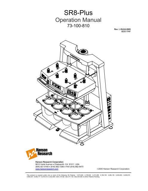
<strong>SR8</strong>-Plus Operation <strong>Manual</strong>73-100-810-ITable of ContentsWhat’s New _______________________________________________________ iv1 Safety Considerations ____________________________________________11.1 General_________________________________________________________________ 11.2 Safety Markings_________________________________________________________ 11.3 Canadian Emissions Notice ______________________________________________ 22 Introduction ____________________________________________________32.1 General_________________________________________________________________ 32.2 Firmware Revisions _____________________________________________________ 43 Specifications ___________________________________________________64 Installation _____________________________________________________74.1 Location________________________________________________________________ 74.2 Unpacking and Inspection _______________________________________________ 84.3 Identification____________________________________________________________ 94.4 Installation Steps ______________________________________________________ 104.5 Start Up _______________________________________________________________ 134.6 Leveling _______________________________________________________________ 134.7 Bath Installation _______________________________________________________ 144.8 Printer Installation _____________________________________________________ 184.9 System Check _________________________________________________________ 194.10 Setting Adjustable Stops _______________________________________________ 204.11 Installation of Paddles and Baskets______________________________________ 214.12 Connecting the E-Probe ________________________________________________ 224.13 Adjusting Sample Probes _______________________________________________ 224.14 Adjusting Digital Temperature Probes ___________________________________ 235 Operation and Programming______________________________________245.1 Keypad Description ____________________________________________________ 245.2 Indicator Lights ________________________________________________________ 255.3 Screen Icons___________________________________________________________ 255.4 Main Screen ___________________________________________________________ 265.5 Use of Scrolls__________________________________________________________ 265.6 Input of Alphabetical Characters ________________________________________ 275.7 <strong>Manual</strong> / Quick Operation _______________________________________________ 29Table of Contentsi
<strong>SR8</strong>-Plus Operation <strong>Manual</strong>73-100-810-I5.8 Print Options __________________________________________________________ 295.9 System Options ________________________________________________________ 305.10 Adjusting the Contrast _________________________________________________ 305.11 Heater Shutdown_______________________________________________________ 305.12 Validation _____________________________________________________________ 305.13 Calibration_____________________________________________________________ 315.14 Security _______________________________________________________________ 315.15 Adding, Changing or Removing Users ___________________________________ 325.16 Diagnostics____________________________________________________________ 325.17 System Configuration Parameters _______________________________________ 325.18 Timer / Alarm Operation ________________________________________________ 355.19 Selecting Creating and Viewing Protocol Parameters _____________________ 385.20 Entering Protocol Parameters ___________________________________________ 385.21 Editing a Protocol ______________________________________________________ 405.22 Viewing Protocol Parameters ___________________________________________ 405.23 Running A Test ________________________________________________________ 405.24 Starting a Protocol _____________________________________________________ 415.25 Starting the <strong>Manual</strong> Timer ______________________________________________ 435.26 System Shutdown and Start Up _________________________________________ 445.27 Stand By Mode_________________________________________________________ 445.28 Serial Number Log _____________________________________________________ 455.29 Software Flow Chart____________________________________________________ 466 Running A Test_________________________________________________476.1 Setting Up _____________________________________________________________ 476.2 Starting and Running a Test (no Digital Temperature Probes) _____________ 476.3 Vessel Temperature Log (no Digital Temperature Probes) _________________ 486.4 Starting and Running a Test (with Digital Temperature Probes / E-Probes)__ 486.5 During the Test ________________________________________________________ 496.6 After the Test __________________________________________________________ 497 Troubleshooting ________________________________________________507.1 Contacting Hanson Research Corporation for Technical Support __________ 507.2 Troubleshooting Table _________________________________________________ 507.3 Diagnostic Tests _______________________________________________________ 52Table of Contentsii
<strong>SR8</strong>-Plus Operation <strong>Manual</strong>73-100-810-I8 Maintenance and Calibration _____________________________________538.1 Maintenance Schedule _________________________________________________ 538.2 Clean Up Procedure ____________________________________________________ 538.3 Circulating Water Pump ________________________________________________ 538.4 Bath Water ____________________________________________________________ 538.5 Temperature Check and Calibration _____________________________________ 548.6 Temperature Probe Offset Adjustment ___________________________________ 548.7 Temperature Probe Calibration__________________________________________ 548.8 Bath Temperature Calibration ___________________________________________ 568.9 Guide Rods ____________________________________________________________ 578.10 Spindle Bearings_______________________________________________________ 578.11 Belts __________________________________________________________________ 588.12 Idler Pulleys ___________________________________________________________ 628.13 Fuse Replacement _____________________________________________________ 628.14 Maintenance Log_______________________________________________________ 638.15 Tablet Calibration ______________________________________________________ 639 Moving and Storage _____________________________________________649.1 Storage________________________________________________________________ 649.2 Moving ________________________________________________________________ 6410 Service Parts _________________________________________________6511 Sales and Support_____________________________________________6612 General Warranty _____________________________________________67Table of Contentsiii
<strong>SR8</strong>-Plus Operation <strong>Manual</strong>73-100-810-IWhat’s NewRevision I‣ Circulating Water Pump (P/N 64-710-410/411) replaces Circulating Air Pump (64-705-058/059) throughout operation manual.‣ Section 6—Service Parts updated.‣ Section 8—Maintenance and Calibration: Temperature Probe (8.7) and Bath TemperatureCalibration (8.8) updated.What’s Newiv
<strong>SR8</strong>-Plus Operation <strong>Manual</strong>73-100-810-I1 Safety Considerations1.1 General1. The installation category (overvoltage category) for this instrument is Level II. The LevelII category pertains to equipment that receives its electrical power from a local level,such as an electrical wall outlet.2. This instrument must be connected to a grounded electrical outlet.3. Never work on the electrical components in the system while there is power to the unit.Disconnect power before servicing the instrument.4. Review all safety and environmental precautions pertaining to any chemicals that are tobe used in conjunction with this equipment.1.2 Safety MarkingsFor your own safety, you must observe the following safety warning markings. The safetywarning markings indicate a possible source of danger. At the same time they containinformation on how correct action can avert danger. You will always find safety warningmarkings attached to points of possible danger.Sign Location Safety WarningControlDanger! Supply voltage and supply frequency must be of thevalue specified for the control unit on the serial number taglocated on the rear panel of the <strong>SR8</strong>-Plus control. Allelectrical outlets must be properly grounded.ControlPrinterMotorHeaterCaution: No operator accessible parts inside. Refer servicingto qualified personnel only. Risk of electrical shock. Do notopen.Achtung: Es gibt keine vorn Benutzer zo wanenden Teile.Oberlassen Sie Reparaturen dem qualifizierten Servicefachmann.Hochspannung. Nicht öffnen.Attention: Aucune pièce remplaçable par l’utilisateur. Touteréparation doit être effectuée par un technicien qualifié.Risque d’ electrocution. Ne pas ouvrir.Precaución: No lo abra. Peligro de alto voltaje. El serviciodebe ser implementado por personal calificado.ControlCaution! Turn unit off and remove power cord beforereplacing fuses. Fuses must be replaced with the samecurrent rating and type described next to the fuse holder.Section 1 Safety Considerations – 1 –
<strong>SR8</strong>-Plus Operation <strong>Manual</strong>73-100-810-ISign Location Safety WarningMotorCaution! Motor armature is hot; do not touch.Drive HeadControlControlCaution! Pinch point on both ends of bearing housing (bothguide rods). Keep hands clear when raising or lowering drivehead.Caution! Communication ports must not be connected to atelephone line.Note! Line and Neutral fused separately.ControlInsideControlNote! Chassis terminal. Cable assembly must be properlygrounded to this location.Note! Protective conductor terminal.1.3 Canadian Emissions NoticeThis digital apparatus does not exceed the Class A limits for radio noise emissions fromdigital apparatus set forth in the Radio Interference Regulations of the Canadian Departmentof Communications.Le présent appareil numérique n’émet pas de bruits radioélectriques dépassant les limitesapplicables aux appareils numériques de la classe A prescrites dans les réglements sur lebrouillage radioélectrique édictés par le Ministére des Communications du Canada.Section 1 Safety Considerations – 2 –
<strong>SR8</strong>-Plus Operation <strong>Manual</strong>73-100-810-I2 Introduction2.1 GeneralThe Hanson <strong>SR8</strong>-Plus Dissolution Test Station provides an entirely new approach todissolution testing by incorporating a user interface with built-in virtual instrumenttechnologies. These technologies provide a "smart" system that anticipates and reacts to theneeds of dissolution testing. The <strong>SR8</strong>-Plus incorporates the Hanson SR "Sustained Release"precision drive system and a high-performance maintenance free SR motor.The system can be configured with 6 or 8 vessels and can use both paddles and baskets.Many accessories are available for special sampling conditions, including small volumetesting with 150mL vessels, Transdermal Sandwich testing and ointment cells. Electronicsample probes (E-Probes) may be added to automate sample probe movement, and E-Probes may be connected to many types of autosamplers.By adding Hanson’s new digital temperature probes, the <strong>SR8</strong>-Plus can also monitor vesseltemperature by allowing automatic vessel temperature readings at programmed intervals.The digital temperature probes connect to the sampling probe and if accompanied by the E-Probe will move in and out of the vessel media and gather temperature data. (This data isprintable on the Hanson validation printer.)The <strong>SR8</strong>-Plus control panel includes Easy-Icon program controls and a LCD display withpop-up menus and convenient help screens. The control panel also provides five statuslights, quickly providing the user with instrument status information.To simplify dissolution testing and instill confidence that the test is performed correctly, the<strong>SR8</strong>-Plus allows the user to store 25 test protocols. These protocols contain test parametersincluding but not limited to the speed, temperature, sampling intervals, drug name, anddosage of the dissolution test. During testing, the <strong>SR8</strong>-Plus sends information to the optionalprinter (recommended). The subsequent printout includes a header with specific informationabout the operator, lab, sample, and a status report which provides a record of the motorspeed and waterbath temperature at designated intervals, as well as the high, low, andaverage at the end of the test. The <strong>SR8</strong>-Plus also includes programs for calibration,validation and diagnostics.The <strong>SR8</strong>-Plus has a built-in system of alerts and alarms, which are signaled by a soft chime,a pop-up window on the display, and status lights. These are programmed by the user andhave several functions: they can be used to remind the user to take a sample or change thepH; they alert the user to any error condition; and they remind the user to performmaintenance, such as changing the bath water, and calibration.Understanding that many labs work a single shift, the <strong>SR8</strong>-Plus can be programmed to turnoff the heater when the last test for the day is complete, then "wake-up" the next morning andturn the heater back on so that the waterbath is ready for the first test of the day. The <strong>SR8</strong>-Plus can also be controlled by an external computer. For a list of external commands,contact your local distributor or Hanson Research Corporation directly.Section 2 Introduction – 3 –
<strong>SR8</strong>-Plus Operation <strong>Manual</strong>73-100-810-I2.2 Firmware RevisionsHanson Research Corporation is constantly working to improve our products and to help ourcustomers comply with regulatory requirements. The information below is a history ofsoftware (firmware) changes for the <strong>SR8</strong>-Plus Dissolution Test Station.Version 3.10• Digital Temperature Probes— Incorporates updated operational menus to support useand control of the new Digital Temperature Probes that are now available for the <strong>SR8</strong>-Plus.These probes are designed to take temperatures in each vessel (up to 8), ensuringtemperatures are and remain within the required USP tolerances.• Sample Interval Printing— Printing intervals may be set to correspond to the samplinginterval.• Programmable Infinity Speed— The infinity speed now may be programmed to a differentspeed than 250. This feature allows for special 2-speed tests, such as one run for 4 hoursat 50RPM and then 2 hours at 75RPM.• Improved Analog Probe Calibration— Probe offset calibration has been modified tomake the process easier, with each probe having its own revision information.Version 3.00• Security— This feature allows up to 25 names to be added to a list which contains userswith Manager or Operator privileges. Managers can change system parameters andprotocols. Operators can only view the system parameters and view/run the protocols.• Password Protection— When password protection is enabled from the security menu,the system requires that a valid user log into the system, and that the correct passwordassociated with that user be entered before any system function is allowed. Passwordprotection helps the user comply with the 21CFR regulations.• System Setup Traceability— Whenever any of the system setup parameters arechanged or a maintenance routine is performed, the action is stamped with the date,time, and username.• Protocol Traceability— When protocols are created or edited, they are stamped withthe date, time, and username.• Inactivity Log Out— The system will automatically log out the current user after a periodof inactivity. This period is programmable.• Print Last Test Feature— Everything that is sent to the printer during the test is nowstored in memory. It may be reprinted if a printer problem occurs (paper, ribbon,mechanical). This feature is accessible until the next test is run.• Configurable Header Titles— Titles printed at the beginning of a report have beenexpanded to 8 and can be edited by the system manager.• Configurable Protocol Titles— Information items in protocols can now be edited by thesystem manager to customize protocols.• International Date Formats— The system allows the manager to select one of four dateformats for printing, displaying, and stamping dates.• Screen Icons— New screen icons graphically show password protection status, printingoptions, availability of revision logs, and multiple screens.• Protocol Navigation Improved— The number of screens required to view/edit aprotocol has been reduced for easier navigation.• Improved Diagnostics— Diagnostics has been improved so that readiness of allperipherals connected to the system is assured.• Improved Help— The help system has been revised so that virtually every screen has ahelp window associated with it.• Added Zymark MultiDose G3 interface.Section 2 Introduction – 4 –
<strong>SR8</strong>-Plus Operation <strong>Manual</strong>73-100-810-IVersion 2.10• Added E-Probe operation for Waters Transfer Module.Version 2.00• Increased protocols from 10 to 25.• Added high/low/average printout at end of test.• Added E-Probe operation for AutoPlus.Version 0.98• Added alarm recurrence.• Added temperature probe offset adjustment.Version 0.65• Added serial commands.Section 2 Introduction – 5 –
<strong>SR8</strong>-Plus Operation <strong>Manual</strong>73-100-810-I3 SpecificationsWeight: (complete system, dry) .......................................................................68 kg (150 lbs.) - 115V.............................................................................................................................70 kg (155 lbs.) - 230VWeight: (complete system filled with water) ...................................................106 kg (233 lbs.) - 115V...........................................................................................................................108 kg (238 lbs.) - 230VSize:Height: .......................................................................................................................100 cm (39 in.)Width: ..........................................................................................................................76 cm (30 in.)Depth:..........................................................................................................................59 cm (23 in.)Electrical:Voltage: ................................................................................................115V ± 10% or 230V ± 10%Frequency: ......................................................................................................................... 50/60 HzCurrent: ...................................................................... 12 amps (115V) or 6 amps (230V), 1700 W4 Fuses (TT Type): 115 VAC Units 230 VAC UnitsOne 2 Amp, 250 VAC,One 5 Amp, 250 VAC,Two 15 Amp.One 2 Amp, 250 VAC,One 5 Amp, 250 VAC,Two 8 Amp, 250 VAC.Ambient Temperature Range:.....................................................≥ 5°C below operating temperatureHumidity: ......................................................................................................................................< 85%Spindle Speed:Range:.......................................................................................................................25 to 250 RPMAccuracy: .............................................................................................................................±1 RPMDisplayed To: ......................................................................................................................0.1 RPMVessel Temperature:Programmable Temperature Range: ........................................................................30.0 to 40.0°CAccuracy: ...............................................................................................................................±0.5°CTemperature Probes T1 & T2 (anolog):Range:........................................................................................................................20.0 to 40.0°CAccuracy: ........................................................................................................±0.1°C from 30-40°CDisplayed Resolution:..............................................................................................................0.1°CMinimum Submersion Depth:.................................................................................................45mmResponse Time:.......................................................................................................... < 45 secondsMaximum Number of Probes: ........................................................................................................ 2Digital Temperature Probes:Range:..............................................................................................................................10 to 60°CAccuracy: ........................................................................................................±0.1°C from 30-40°CDisplayed Resolution:............................................................................................................0.01°CMinimum Submersion Depth:.................................................................................................25mmResponse Time:............................................................................< 45 seconds (normally 30 sec.)Maximum Number of Probes: ........................................................................................................ 8Bath Capacity:Without vessels:............................................................................................... 38 liters (10 gallons)With 6 to 8 vessels:............................................................................................ 30 liters (8 gallons)Section 3 Specifications – 6 –
<strong>SR8</strong>-Plus Operation <strong>Manual</strong>73-100-810-I4 Installation4.1 LocationEnvironmental RequirementsThe waterbath temperature must exceed ambient temperature by at least 5°C for maximumperformance of the waterbath control system. Therefore, for the best results the ambienttemperature should not be allowed to exceed 31°C (88°F) for the 37°C tests, or 26°C (79°F)for 32°C tests.A stable ambient room temperature is required. The system should not be placed close to anopen window, an uninsulated window, or a heating radiator, which would cause temperaturefluctuations of more than 2°C per hour. Relative humidity should be 85% or less.Easy access to a water source and waste disposal for filling and emptying the waterbath isconvenient, although not necessary.Dissolution rates are profoundly affected by vibration. Therefore, the system should not beplaced near a centrifuge, fan, compressor or any other source of vibration. The room shouldnot be subject to vibration from adjacent production equipment, such as single head tabletmachines.Space RequirementsThe <strong>SR8</strong>-Plus Dissolution Test Station is designed to be placed on a standard laboratorybench that is at least 60cm (24 inches) deep. The system is 76cm (30 inches) wide andrequires access to the back on both sides. The laboratory bench should be level and flat,although the system has adjustments for self-leveling. The laboratory bench must also becapable of supporting the weight of the Dissolution Test Station, including the water in thewaterbath and media in the vessels. This weight is 108kg (238lbs).Electrical RequirementsThe <strong>SR8</strong>-Plus Dissolution Test Station requires a single, grounded electrical outlet, within 2.5meters (8 feet) of the location of the system. The system has two outlets on its side panel,providing a power source for the circulating water pump and the optional printer.The system is available in two configurations, 115V and 230V. The voltages are set at thefactory and cannot be changed (see model number label on back of control to determinevoltage requirements for that unit).Section 4 Installation – 7 –
<strong>SR8</strong>-Plus Operation <strong>Manual</strong>73-100-810-I4.2 Unpacking and InspectionThe <strong>SR8</strong>-Plus Dissolution Test Station is shipped in two boxes. The larger box, which is heldtogether with two straps, holds the basic system assembly. The smaller box contains anumber of components that must be installed on the basic system assembly, spare parts, andoptional accessories.NOTE: Shortages or damages must be reported immediately to the freight carrier and toHanson Research. Notify Hanson Research Customer Service by telephone (800)821-8165 or by FAX (818) 882-9470.To unpack the system:1. Place the larger box on the floor. Remove the waterbath and packing materials. Thepacking materials can be discarded. Save the packing materials only if the system willbe shipped to another location in the future.2. Locate the locking hardware and hold down the collar on the back of the system, asshown in Figure 4-1. Remove the locking hardware on the left and ride sides. Alsoremove the hold down collar on each guide rod using the hex wrench supplied in thesupply kit. Save the locking hardware and the hold down collars only if the system willbe shipped to another location in the future.Figure 4-1: Removing the Locking Hardware and Holding Collar3. Place the basic system assembly on the lab bench.Open the smaller box. The smaller box contains (1) unassembled parts, (2) supply kit,and (3) accessories. Unpack and identify each of these parts.Section 4 Installation – 8 –
<strong>SR8</strong>-Plus Operation <strong>Manual</strong>73-100-810-I4.3 Identification1. Bath Support2. <strong>SR8</strong>-Plus Controller3. Circulating Water Pump4. Power Cord5. Waterbath6. Vessel Centering Rings7. Vessels8. Drain Hose9. <strong>SR8</strong>-Plus Easi-Lift FrameFigure 4-2: System PartsOpen End WrenchHex WrenchPaddle Spacer(with Paddle order)Basket Spacer(with Basket order)Figure 4-3: Supply KitSection 4 Installation – 9 –
<strong>SR8</strong>-Plus Operation <strong>Manual</strong>73-100-810-IPaddlePrinterBasket & Basket ShaftFigure 4-4: Accessories4.4 Installation StepsCaution: Unit should not be plugged in until installed as per instructions below.Achtung: Das Gerät darf nicht an das Netz angeschlossen werden, bevor es nicht nach denuntenstehenden Instruktionen installiert worden ist.Attention: Ne pas brancher l’appareil avant installation complète comme démontrécidessous.Precaución: La unidad no debe ser conectada al toma corriente hasta que sea instalada deacuerdo a las instrucciones descritas abajo.1. Raise the drive head by holding in the lever with the left hand, while pushing up on thehandle. (see Figure 4-5)Section 4 Installation – 10 –
<strong>SR8</strong>-Plus Operation <strong>Manual</strong>73-100-810-IFigure 4-5: Raising the Drive Head2. Lower and raise the drive head to verify that it moves smoothly over the full range ofmotion. Position the drive head at its highest location. Release lever to activate thebrake.3. Position the <strong>SR8</strong>-Plus Controller on the back rail of the basic system assembly. (seeFigure 4-6)Figure 4-6: Positioning the ControllerSection 4 Installation – 11 –
<strong>SR8</strong>-Plus Operation <strong>Manual</strong>73-100-810-I4. Notice that there are a series of connectors on the right-hand side of the <strong>SR8</strong>-Pluscontroller. (see Figure 4-6)a) Connect ground strap to ground connector.b) Plug the motor cable into the connector labeled “MOTOR”. Make sure to line up thekeyways in the plug with the slot in the socket, push plug in and then turn the ring onthe plug to secure.c) Plug the user interface cable into the connector labeled “DRIVE”. Evenly tighten thescrews that secure the plug to the controller.NOTE: If the E-Probe has been supplied with the system, the E-Probe power cord is thesmaller of the two power cords supplied. Do not switch these two power cords;always use the heavier main power cord for the control.d) Connect the power cord into the connector labeled “AC-INPUT”.5. Secure the <strong>SR8</strong>-Plus Controller to the Easi-Lift Frame by pulling the “S-Hook” andinserting it into the metal loop in the frame. (see Figure 4-7)Figure 4-7: Securing the <strong>SR8</strong>-Plus ControllerSection 4 Installation – 12 –
<strong>SR8</strong>-Plus Operation <strong>Manual</strong>73-100-810-I4.5 Start UpCaution: The voltage indicated on the <strong>SR8</strong>-Plus Dissolution Test Station must be the sameas the power source. If the incorrect voltage is indicated, do not plug in the instrument.Contact Hanson Research.Achtung: Die angezeigte Spannung am <strong>SR8</strong>-Plus Dissolutionstester muβ die gleiche sein,wie die Netzpannung. Wird nicht die korrekte Netzspannung angezeigt, darf das Gerät nichtan das Netz angeschlossen werden, Wenden Sie sich bitte diesbezûglich sofort an die FirmaHanson Research.Attention: Le voltage indiqué sur le Système de Dissolution <strong>SR8</strong>-Plus doit être identique àcelui de la source de courant. Si le voltage diffère, ne pas brancher l’appareil avant deconsulter Hanson Research.Precaución: El Voltaje indicado en la Unidad de Disolución <strong>SR8</strong>-Plus debe ser el mismovoltaje del toma corriente. Por lo tanto si el voltaje es diferente, no conecte la unidad ynotifique a Hanson Research.1. Verify that the voltage indicated on the back of the controller is the same as the powersource.2. Plug the other end of the power cord into the grounded three-prong power outlet.NOTE: Power cord plug may need to be replaced for some countries’ power outletconfigurations. Ensure replacement plug is approved and properly rated for voltageand amperage.3. Turn on the power switch, located on the right hand side of the <strong>SR8</strong>-Plus Controller.4. The “Power On” status light on the front panel should illuminate. A title screen appearsfor 5 seconds and then the main screen is displayed.5. Turn the power switch off and un-plug the power cord from the grounded three-prongpower outlet.4.6 LevelingTools required:Level (not supplied) and small open end wrench (supplied in tool kit).For proper operation, the <strong>SR8</strong>-Plus Dissolution Test Station must be level. Most laboratorybenches are level, so minimal adjustment may be necessary.Each of the four feet on the <strong>SR8</strong>-Plus is adjustable. Place the level on the base plate asshown in Figure 4-8. Check the level, both left to right and front to back. If necessary, raiseany of the feet, using the open-end wrench, turning in a clockwise direction. Make sure allfeet are contacting the bench when finished.Section 4 Installation – 13 –
<strong>SR8</strong>-Plus Operation <strong>Manual</strong>73-100-810-IFigure 4-8: Leveling4.7 Bath Installation1. Position the bath support on the lab bench so that it is touching the back of the <strong>SR8</strong>-Plusframe and is centered left to right. The open gap should be towards the front. (seeFigure 4-9)Figure 4-9: Positioning the Bath Support2. With the heater toward the back, slide in the bath on top of the bath support. (seeFigure 4-10)Section 4 Installation – 14 –
<strong>SR8</strong>-Plus Operation <strong>Manual</strong>73-100-810-IFigure 4-10: Positioning the Bath3. Plug the heater cable into the connector labeled “Heater” on the right-hand side of the<strong>SR8</strong>-Plus Controller. (see Figure 4-9)4. Position the bath so that it is touching the back of the <strong>SR8</strong>-Plus frame and is centered inthe frame from left to right.5. Route the cable from the bath level sensor under the frame on the left-hand side of thesystem.6. Plug the bath level sensor into the connector labeled “LEVEL SENSOR”, located on theleft hand side of the <strong>SR8</strong>-Plus Controller.7. Fill the bath half full (approximately 5 gallons) of water (DI or better).NOTE: Do not use copper sulfate as an algaeecide.8. Install the vessel centering rings in each of the vessel openings in the base plate. Pushrings down into each hole until it snaps in. (Use of these rings ensures that the vesselsare centered so that they meet regulatory requirements). (see Figure 4-11)9. The vessel positions are on the base plate. Insert the number of vessels normally usedin the vessel centering rings, starting with Position 1. Turn the clamp knobs over the lipof the vessel to hold each vessel in place. (see Figure 4-11)Section 4 Installation – 15 –
<strong>SR8</strong>-Plus Operation <strong>Manual</strong>73-100-810-IFigure 4-11: Positioning the Vessels10. Use DI (or better) water to fill the bath to the desired level. (This level is usually at leastto the 900 mL mark on the vessels.)11. Install the Circulating Water Pump. (see Figure 4-12)a) Install the circulating water pump into the bath through the Vessel #1 hole. Place itas low in the bath as possible without the case of the pump touching the bath wall.b) Center the circulating water pump between Vessels 1 & 2 and press the pump’s feetto the inside of the bath wall. The outlet of the pump should be pointing towards theheater and the power cord should be pointing up.c) Pull the bath out away from the dissolution station enough to where the end of thepower cord can be routed out and over the top back portion of the bath. Whenfinished, the cord should be coming out over the back right corner of the bath withinthe groove.d) Make sure the power cord is not in anyway pinched or pressed by the bath or theframe.e) Plug the circulating water pump into the power outlet labeled “AIR PUMP” on theright hand side of the <strong>SR8</strong>-Plus Controller.f) The only maintenance for the circulating water pump is to ensure that the waterbathis reasonably clean.NOTE: The circulating water pump is 115V and must be plugged into the “AIR PUMP” poweroutlet on the <strong>SR8</strong>-Plus Controller.Section 4 Installation – 16 –
<strong>SR8</strong>-Plus Operation <strong>Manual</strong>73-100-810-IFigure 4-12: Circulating Water Pump Connection12. Install the temperature probes(s). (see Figure 4-13)NOTE: The system is designed to operate with either one or two temperature probes. One issupplied with the system, the other is optional. Probe 1 is designed to be placed inthe bath. Probe 2 can be placed in Vessel 7 or 8 if they are not used for testing, or atthe opposite end of the bath.a) Plug the temperature probe(s) into the connector(s) labeled “TEMP PROBES” onthe left hand side of the <strong>SR8</strong>-Plus Controller. The first probe must be plugged intoconnector “1”, and the optional second probe must be plugged into connector “2”.b) For Probe 1, route the cable around the side of the bath and place the temperatureprobe into the bath, using one of the two holes indicated in Figure 13. Push thetemperature probe into the bath as far as it will go.c) For Probe 2, route the cable behind the bath and place the temperature probe intoeither Vessel 7 or 8. Secure the probe so that it remains in the vessel.Section 4 Installation – 17 –
<strong>SR8</strong>-Plus Operation <strong>Manual</strong>73-100-810-IFigure 4-13: Temperature Probe Installation4.8 Printer InstallationThe printer may be installed in one of two configurations: Standard or Daisy-chained.Standard is the more common configuration where each <strong>SR8</strong>-Plus installed is connected toits own printer. In the Daisy-chained configuration, several <strong>SR8</strong>-Plus Dissolution TestStations are connected to a single printer.NOTE: Refer to the operating instructions provided with the printer for information on paperand ribbon installation.Standard Configuration1. Plug the printer into the power outlet labeled “PRINTER” on the right hand side of the<strong>SR8</strong>-Plus Controller.NOTE: The printer is 115V and must be plugged into the printer power outlet on the <strong>SR8</strong>-Plus Controller. The printer should be placed away from the test area to keep it frombeing damaged by liquid.2. Plug the cable connected to the printer into the port connector labeled “COMM PORT 3”on the left hand side of the <strong>SR8</strong>-Plus Controller.Section 4 Installation – 18 –
<strong>SR8</strong>-Plus Operation <strong>Manual</strong>73-100-810-IDaisychained Configuration1. Plug the printer into the power outlet labeled “PRINTER” on the right hand side of thelast <strong>SR8</strong>-Plus in the chain.NOTE: The Printer is 115V and must be plugged into the printer power outlet on the <strong>SR8</strong>-Plus Controller.2. Plug a communications cable from “COMM PORT 2” of the first unit in the chain to“COMM PORT 1” of the next unit and repeat this procedure for the number of unitsdaisy-chained. At the last unit in the chain plug the cable connected to the printer intothe port connector labeled “COMM PORT 3” on the left hand side of the <strong>SR8</strong>-PlusController.3. On the last unit in the chain (the one connected to the printer), press [Preferences],select [1] DEVICE SET<strong>UP</strong>, and use [1] to select the “PRINTER: Yes” option. On allother units in the chain select the “PRINTER: Remote” option.4. The units in the chain that have their printers set to “Remote” will send the data out oftheir “COMM PORT 2” and into “COMM PORT 1” of the next unit. The printer at the endof the chain with printer option set to “Yes” will send the data into “COMM PORT 3” andinto the printer.4.9 System CheckCaution: Plug the power cord into the grounded three prong power outlet.Achtung: Stecken Sie den Stecker in die Dreier-Basis-Steckdose.Attention: Brancher le fil conducteur de courant à la prise de terre.Precaución: La unidad debe conectarse a un toma corriente que tenga conexión de tierra (de tres terminales ).1. Turn on the power switch, located on the right hand side of the <strong>SR8</strong>-Plus Controller.2. The “Power On” status on the front panel should illuminate. A title screen appears for 5seconds and then the Main screen is displayed.Section 4 Installation – 19 –
<strong>SR8</strong>-Plus Operation <strong>Manual</strong>73-100-810-I3. Verify that the heater is working properly. Press [SET TEMPERATURE].Use the [↑] and [↓] arrow keys to highlight 37.0, and press [ENTER]. The “Heater On”status light should illuminate.4. The heater should raise the bath temperature to close to 37°C within 30 minutes andequilibrate at 37° in one hour. The temperature can be monitored on the status screen.5. Run a diagnostics test and verify that all the tests pass.NOTE: If any test fails or if the bath does not heat, contact Hanson Research TechnicalSupport at (800) 821-8165 or (818) 882-7266.4.10 Setting Adjustable Stops1. Raise the drive head to its highest position.2. Use a hex wrench (supplied in the supply kit) to loosen the Adjustable Stops. Set thestops to where there is 38mm (1.5”) of distance between the Adjustable Stop and thesupport that is on top of the base. The width of all height spacers is 38mm; an easy wayto set this distance is to use the height spacer on its side and place it between the stopand the support. Set one of the Adjustable Stops this way. Tighten this stop to lock inposition. Lower drive head so that it touches this stop and then lift the secondAdjustable Stop so that it touches the drive and lock into place.Figure 4-14: Setting Adjustable StopsSection 4 Installation – 20 –
<strong>SR8</strong>-Plus Operation <strong>Manual</strong>73-100-810-I4.11 Installation of Paddles and Baskets1. Verify that the drive head is at its highest position.3. If the spindles are turning, press [SET SPEED], highlight “0” or input “0”, and press[ENTER]. The spindles will stop turning.4. Reach under the drive head and loosen the chuck which secures the shaft of eachpaddle or basket. Insert each shaft through the chuck, so that it is protruding out the topof the drive head. (see Figure 4-15)Figure 4-15: Paddle/Basket Shaft Installation5. Verify that each of the vessels is empty.6. Verify that there are no spacers installed on the guide rods. (see Figure 4-14)7. Lower the drive head to its lowest position.NOTE: If a different operating position is desired, see 4.10 Setting Adjustable Stops.8. Push each shaft down until the paddle or basket touches the bottom of the vessel.Tighten the chuck to secure the shaft in place.9. Raise the drive head.10. Clip the height setting spacers above the stops on the guide rods. If using paddles, usethe spacer labeled “P”. If using baskets, use the spacer labeled “B”. This meets theUSP specification for spacing.Section 4 Installation – 21 –
<strong>SR8</strong>-Plus Operation <strong>Manual</strong>73-100-810-I4.12 Connecting the E-ProbeNOTE: The E-Probe power cord is the smaller of the two power cords supplied. Do notswitch these two power cords; always use the heavier, main power cord for control.1. Connect the power supply (black rectangular box, with plug) into the round connectorcoming out with tubing and the other connectors on the right side of the <strong>SR8</strong>-Plus.2. Loop cable around and clamp with cable tie. The power supply may become unpluggedif this is not done.3. Connect the power cord into the side of the power supply. Connect the other end of thepower cord into a grounded outlet.4.13 Adjusting Sample ProbesThe tip of the sampling probe should be midway between the top of the media and the top ofthe paddle or basket.To adjust E-Probe sampling probes:1. Make sure probe is at the top of the stroke. If you are not sure, home probes. (seeSection 5.17--System Configuration Parameters: E-Probe Setup)2. Have the <strong>SR8</strong>-Plus mechanical settings adjusted and ready to start the test.3. Select the Protocol to run and with the “Drop Dose and Press Run” window shown,press the down arrow to lower the probe by the stroke amount for that protocol.4. Loosen the thumb-screw on the upper coupler and slide the sampling tube up or down toachieve the correct sampling position and tighten the thumb-screw to lock the samplingprobe in place.Section 4 Installation – 22 –
<strong>SR8</strong>-Plus Operation <strong>Manual</strong>73-100-810-I5. Press the up arrow to return the sampling probes to the home position.NOTE: The probe will only move if a stroke value has been entered into the protocol. Alwaysset the stroke to 45mm unless there is a requirement to stroke a different amount.4.14 Adjusting Digital Temperature ProbesThe tip of the Digital Temperature Probes should be adjusted to the tip of the sampling probeor its filter.To adjust Digital Temperature Probes:1. Make sure that the E-Probes are at the top of their stroke. If you are not sure, homeprobes. (see Section 5.17--System Configuration Parameters: E-Probe Setup)2. Have the <strong>SR8</strong>-Plus mechanical settings adjusted and ready to start the test.3. The Digital Temperature Probe is designed to clip onto the sampling probe. Move theDigital Temperature Probes up or down so that the tip of the Digital Temperature Probeis at the same level as the tip of the sampling probe or sampling filter.Section 4 Installation – 23 –
<strong>SR8</strong>-Plus Operation <strong>Manual</strong>73-100-810-I5.1 Keypad DescriptionKey Key Name Use5 Operation and ProgrammingRunSpeedThe first press of this key allows the user to select a storedprotocol. The second press of this key starts the selectedprotocol.This key allows the user to manually set the speed. Thiskey is not functional when a protocol is running.TemperatureEdit/View ProtocolPreferencesPrint OptionsThis key allows the user to manually set the temperatureand to view the Digital Temperature Probe screen (whenDigital Temperature Probes are installed).This key is used to select the parameters for a new protocol.This key is also used to edit/view the parameters of a storedprotocol. A password may be required to changeparameters.This key is used to access a series of options that aresecondary to the normal operation of the system. Theseinclude: contrast adjustment for the LCD display, heatershutdown option at the end of a test, validation andcalibration options, security and user options, diagnostics,and system configuration.This key is used to access print options. These include:print status, print protocol, print header and print last test.StopThis key is used to abort a test in progress. Press twice toabort test. If this key is pressed when there is no test inprogress, the system is placed in the standby mode.ClockHelpThis key is used to access the clock and alarm options.These include: clock options, preheat wakeup alarm,sampling alarm, user alarms, calibration alarm, alarmacknowledgment and start manual timer. This key is alsoused to access revision information when available.This key is used to access the help screens for the system.Section 5 Operation and Programming – 24 –
<strong>SR8</strong>-Plus Operation <strong>Manual</strong>73-100-810-I5.2 Indicator LightsPower OnHeater OnStand ByThis light indicates power is supplied to the system.This light indicates the system is heating the waterbath. Whenever thewaterbath target temperature is increased, this light remains illuminated. Asthe bath nears target temperature, the light begins turning on and off, with theon time diminishing to only a few seconds per minute to maintain temperatureonce the target temperature is reached.This light indicates the system is in stand-by mode. This light blinks wheneverthe wakeup alarm has been activated in the stand-by mode.Diagnostics An energized light indicates the system detects a fault, which is fatal to its use.Timer Alert An energized light indicates an alarm has been activated. This light turns offautomatically whenever the alarm is acknowledged.5.3 Screen IconsThese icons are located on many system screens. Their purposes are:ClockPrinterLock OpenPress to view the current revision for that setting.Press to print the current screen information.Indicates that the security system is enabled and that a manager is logged on.Lock Closed Indicates that the security system is enabled and that an operator is logged on.NOTE: If no locks appear on any of the screens, this is an indication that the security systemis turned off.Figure 5-1: Screen IconsSection 5 Operation and Programming – 25 –
<strong>SR8</strong>-Plus Operation <strong>Manual</strong>73-100-810-I5.4 Main ScreenWhenever the system is powered up, a Title screen is displayed for a few seconds and thenthe Main screen is displayed, as shown in Figure 5-2.0:000:000:000:00Figure 5-2: Main ScreenNotice that there are three tabs on the Main screen: Status, Set Point, and Header. Theseare the three screens that comprise the Main screen. In the Figure, the Status screen isdisplayed. Press [→] and/or [←] to display the other screens. The Status screen is normallydisplayed when the system is operating. In most cases, if one of the Main screens is notdisplayed, it can be displayed by pressing [ESC] one or more times.5.5 Use of ScrollsThe user selects the desired input to operating parameters using a scroll. An example of ascroll is shown in Figure 5-3. This can be displayed by pressing[SET SPEED]Figure 5-3: Example ScrollIf the desired input for the parameter is displayed in the scroll, press [↑] and/or [↓] to highlightit and press [ENTER]. The scroll holds 5 inputs. Each time an input is selected, it is placedat the top of the scroll. Pressing [ENTER] again will set or implement this value. In the caseabove the speed will go to 50RPM.Section 5 Operation and Programming – 26 –
<strong>SR8</strong>-Plus Operation <strong>Manual</strong>73-100-810-IIf the desired input is not displayed, key in the input and press [ENTER]. The input is placedat the top of the scroll and highlighted. If the scroll had been full with 5 inputs, the input at thebottom of the scroll is deleted and the new input is placed at the top of the scroll. Press[ENTER] to accept the highlighted input.Press [CLR] to delete the highlighted input, if necessary.Some parameters, such as the drive speed, require numeric input. Other parameters, suchas the operator's name, require alphabetic input. Input of alphabetical characters isdescribed later in this section.5.6 Input of Alphabetical CharactersAn example of a screen which requires an input of alphabetical characters is shown in Figure5-4. To display this screen, with the Status screen displayed, press [→], [→] to display theHeader screen. Then press [0] to display the "Operator Name" input screen. If the desiredoperator's name is highlighted on the scroll, it can be selected as described above.Figure 5-4: Header ScreenTo input a new operator's name:1. Note that the operating keys also include the letters of the alphabet. For example,[RUN] has "abc" attached.2. Successive presses of the key display the letters sequentially. For example, pressing[RUN] one time displays an "a". Pressing it a second time displays a "b".Pressing it a third time displays a "c". Continuing to press [RUN] will take letters to theuppercase format and then back to lowercase.3. When the desired letter is displayed, press [→] to move to the next character. Pressing[→] again leaves a space. Pressing [←] allows any character to be overwritten.Pressing [ESC] or [CLR] deletes the entire input.NOTE: It is not necessary to press [→] to move to the next character, unless the next letteruses the same key. This is more clearly explained in the following example.Section 5 Operation and Programming – 27 –
<strong>SR8</strong>-Plus Operation <strong>Manual</strong>73-100-810-I4. The third character on [HELP] allows a choice of 22 special characters to beinput. These characters are displayed in the pop-up window. Use [→] or [←] to highlightthe desired character, then press [ENTER] to place the character in the input string.As an example, input the operator's name "Bill Smith".1. Press [RUN] five times to display a "B".2. Press [SET TEMPERATURE] three times to display an "i".3. Press [EDIT/VIEW PROTOCOL] three times to display an "l".4. Press [→] to move to the next space.5. Press [EDIT/VIEW PROTOCOL] three times to display an "l".6. Press [→] twice to leave a space.7. Press [STOP] four times to display an "S".8. Press [PREFERENCES] to display an "m".9. Press [SET TEMPERATURE] three times to display an "i".10. Press [STOP] two times to display a "t".11. Press [SET TEMPERATURE] two times to display an "h".12. Press [ENTER] to place “Bill Smith” at the top of the scroll.13. Press [ENTER] to accept the highlighted input.Section 5 Operation and Programming – 28 –
<strong>SR8</strong>-Plus Operation <strong>Manual</strong>73-100-810-I5.7 <strong>Manual</strong> / Quick OperationThe <strong>SR8</strong>-Plus is designed to perform dissolution testing using a series of dissolutionparameters stored in a protocol. Under certain conditions, it is desirable to have manualcontrol of the speed and temperature. Use [SET SPEED] and [SETTEMPERATURE] to manually adjust these parameters when a protocol is not running, orbefore starting the manual timer.5.8 Print OptionsThe Print Options Menu provides the user with the four choices described below. The menualso shows the status of the system printer.Figure 5-5: Print Options ScreenPrint StatusPressing [1] allows the user to print the current status (speed, temperature and elapsed time)at any time.Print Protocol1. Press [2] to select “Print Protocol”. The Select Protocol screen is displayed.2. Highlight the desired protocol and press [ENTER]. The protocol parameters are printed.3. When printing is complete, press [ESC].Print HeaderPress [3] to select “Print Header”. The title is printed.Print Last TestPress [4] to select “Print Last Test”. The test that was last completed is stored in the systembuffer; each time a test is started this buffer is over-written.Section 5 Operation and Programming – 29 –
<strong>SR8</strong>-Plus Operation <strong>Manual</strong>73-100-810-I5.9 System OptionsThe <strong>SR8</strong>-Plus System has a number of parameters that can be input by the user as part ofthe installation procedure. Under normal operating conditions, these parameters are notchanged, although they can be at any time.5.10 Adjusting the ContrastTo adjust the contrast on the LCD display:1. With the Main screen displayed, press [PREFERENCES] to display the SystemOptions screen.2. Press [1] to select "Adjust Contrast". The Adjust Contrast screen is displayed. Press[←] to make the display darker; press [→] to make the display brighter.3. When the contrast is set to the desirable contrast, press [ENTER] to return to theSystem Options screen.5.11 Heater Shutdown1. With the Main screen displayed, press [PREFERENCES] to display the SystemOptions screen.2. Press [2] to change "Heater Stays On" to "Heater Shutdown".3. Press [ESC] to return to the System Options screen.NOTE: The heater will shutdown after this test only. If the test is stopped, the “HeaterShutdown” will return to “Heater Stays On”. This feature may be changed during atest.5.12 ValidationWith the System Options screen displayed, press [3] to display the System Validation Menuscreen.1. Press [1] to log vessel temperatures with probe T1. Follow the directions on the screento record or print each vessel temperature. It is best to wait at least 30 secondsbetween readings.2. Press [2] to log serial numbers. There are multiple screens to enter serial numbers forvessels, paddles, basket shafts, baskets and the <strong>SR8</strong>-Plus system components. If thesystem is equipped with Digital Temperature Probes, a screen with their serial numberswill be displayed. The Digital Temperature Probe serial numbers are not changeable.Section 5 Operation and Programming – 30 –
<strong>SR8</strong>-Plus Operation <strong>Manual</strong>73-100-810-I3. Press [3] to view the maintenance log. The information on this screen tells the user orservice person when the components of the system were calibrated and the operatingtime of the belt, motor, and heater. This information should only be modified if servicehas been done to the unit. If the system is equipped with Digital Temperature Probes, ascreen with their calibration information will be displayed.5.13 CalibrationWith the System Options screen displayed, press [4] to display the System Calibration Menuscreen. Calibration of the system is explained in Section 8—Maintenance and Calibration.5.14 SecurityWhen the security system is enabled, only personnel previously entered into the system by amanager may log on and access operational functions. This feature is highly recommendedand, once in place, all personnel are required to log on to operate the unit. There may be upto 25 users programmed into the unit, and there are two levels of users:Manager (open lock)Complete access to all functions settings and operation of the unit.Operator (closed lock) Limited access and may not modify settings or protocols, but canstart pre-programmed protocols. The operator may also view andprint protocols and system settings.When changes are made by a manager, a revision log is kept indicating when the changewas made, and by whom. The revision log may be displayed by pressing the clock key whenthe small clock icon appears at the bottom of the screen.NOTE: The security system may be disabled, although there will be no protection ofimportant system settings and protocols.Setting Up and Starting the Security System1. With the Main screen displayed, press [PREFERENCES] to display the SystemOptions screen.2. Press [5] "Security".3. Highlight “Manager” and press [ENTER].4. Follow the directions at the bottom of the screen to enter a password.5. Highlight “Manager” again and press [ENTER].6. Re-enter your password and press [ENTER] and again [ENTER]. You are now at theManager Menu.7. Press [1] to enable the password protection. Press [4] to change the password timeout(default is 5 minutes).Section 5 Operation and Programming – 31 –
<strong>SR8</strong>-Plus Operation <strong>Manual</strong>73-100-810-I8. Press [2] to add a user, press [1] to add a manager, enter your name and press[ENTER]. Press [ESC] and again [ESC] to get to the Password screen. Highlight yourname (or the name you just entered) and follow the instructions to input your password.[ESC] to return to the Main Menu.9. Press [STOP] and again [STOP] to log off. Press [PREFERENCES], and you are nowrequired to log on. Highlight your name (or the name you entered in Step 8 and press[ENTER]; enter your password and press [ENTER]. You have now logged on.NOTE: Enable password and set time and date (see more in this section) before changingany system settings or creating protocols; this will ensure that the revision dates forthese areas are correct.5.15 Adding, Changing or Removing Users1. When you are classified as a manager you may add managers or operators, and youmay change an operator to a manager or a manager to an operator. To log into theManager Menu from the Main Menu, press [PREFERENCES], [5] “Security”, and thenhighlight your name and enter your password and press [ENTER] and again [ENTER] toview the Manager Menu.2. At the Manager Menu select “Add A New User” to add a manager or operator.3. At the Manager Menu select “Modify/Delete A User” to remove or change someone inthe list of users.5.16 DiagnosticsIt is recommended to run diagnostics at the beginning of each day’s work or if there has beena change or a problem with the equipment. Diagnostics is explained in more detail in Section7—Troubleshooting.5.17 System Configuration ParametersWith the Main screen displayed, press[PREFERENCES] to display the SystemOptions screen. To set the system configuration parameters, press [7] to display the SystemConfiguration screen.Figure 5-6: System Configuration ScreenSection 5 Operation and Programming – 32 –
<strong>SR8</strong>-Plus Operation <strong>Manual</strong>73-100-810-IDevice Setup1. At the System Configuration screen press [1] to select "Device Setup". The DeviceSetup screen is displayed.2. Press the number for each of the accessories to display the installation status of eachaccessory. The system checks for these accessories when the Diagnostic tests areperformed and at the beginning of each test. A failure is indicated if any of the indicatedaccessories are not found. Make sure the display shows only the accessories that areconnected to the system.3. Press [2] to select “USP Tolerances On” or “USP Tolerances Off”.NOTE: When USP tolerances are on, the user can only start a test when all USP-specifiedparameters are within USP tolerances. Parameters that fall out of these tolerancesduring a test are printed stating nature of error and time error occurred. When USPtolerances are off, tests can be started with the temperature not up to the setting.System ID1. At the System Configuration screen press [2] to select "System ID". The System IDscreen is displayed.2. Input the System ID. This is printed with the status information. It can be used toidentify which dissolution system is being used, if the laboratory has more than onesystem. This is also used for identification when the system is operated remotely.Edit TitlesPress [3] to select "Edit Titles". The Title Configuration screen is displayed, showing thechoices that are available. To configure these titles;1. Select the type of title that is to be changed--company, header or protocol. Thecompany name includes two lines of information which are printed at the start of eachtest. These two lines are suggested to be the company and department names. TheHeader Titles will appear and be printed at the start of a test. The Protocol Titles arelocated in protocols and printed at the start of each test.2. Select the corresponding number associated with the title(s) that are to be changed.Enter in the new title.NOTE: Blank title areas are not printed.Language SelectionPress [4] to select “Languages".NOTE: English is the default language. Consult the factory for a list of currently availablelanguage choices.Section 5 Operation and Programming – 33 –
<strong>SR8</strong>-Plus Operation <strong>Manual</strong>73-100-810-IRS-232 SetupPress [5] to select and view the “RS232 Setup” screen.The RS232 parameters are the following:1. Baud Rate— Determines the transmission/reception speed of data between the <strong>SR8</strong>-Plus and the external computer. The available baud rates are 1200, 2400, 4800 and9600 ∗ .2. Data Bits— An integer indicating the number of data bits to be used in transmitting eachsingle character. The available options are 7 or 8 ∗ characters.3. Parity— Indicates the type of parity checking that is used during communications. Theavailable options are ODD, EVEN and NONE ∗ .4. Command Echo— When this parameter is ON ∗ , the <strong>SR8</strong>-Plus returns (or echoes back)the System ID of the unit (truncated to 6 characters) followed by the command numberonce it is successfully implemented. When the parameter is OFF, no response is sentback to the external device whether command implementation was successful or not.NOTE: The parameters selected here are for external computer handshakes and do notaffect <strong>SR8</strong> Plus communications with the system printer which always remain at thefactory default settings ∗ of 9600 (Baud Rate), None (Parity), 8 (Data Bits), 1 (StopBits) and On (Command Echo).E-Probe SetupThe E-Probe Setup allows the user to operate the probes. If it has not been selected fromthe accessories screen, it will not show up in the System Configuration screen. Pressing [1]will home the probes. Always make sure to select the correct stroke value. Press the up ordown arrows to check probe operation and to make probe adjustments.Section 5 Operation and Programming – 34 –
<strong>SR8</strong>-Plus Operation <strong>Manual</strong>73-100-810-I5.18 Timer / Alarm OperationDate and TimeTo set the system time and date:1. With the Main screen displayed, press [CLOCK] to display the SystemAlarm/Timers screen.2. Press [5] to display the "Clock Options".[1] to change the time format from 12 to 24 and back.[2] to allow change to the displayed time.[3] to change the date format, continue to press to review all date formats.[4] to allow change to the displayed date.Preheat Wakeup TimeThe preheat wakeup time option allows the user to program the <strong>SR8</strong>-Plus to turn on theheater to a designated temperature at a designated time on a designated day, so that thebath temperature is equilibrated when the user is ready to use the system. The most typicaluse of this option is for the heater to be turned on approximately 1 hour before starting time inthe morning. To set the preheat wakeup time:1. With the Main screen displayed, press [CLOCK] to display the SystemAlarm/Timers screen.2. Press [1] to select "Preheat Wakeup". The Preheat Wakeup Time screen is displayed.3. Input the time, date, recurrence and temperature. Follow each input with [ENTER].NOTE: Past date and time cannot be entered for any alarm.Section 5 Operation and Programming – 35 –
<strong>SR8</strong>-Plus Operation <strong>Manual</strong>73-100-810-ISampling AlarmThis alarm is used to alert the user when a sample is to be taken from the vessels, asdetermined by the sampling interval set in the protocol. To set the parameters for thesampling alarm:1. With the Main screen displayed, press [CLOCK] to display the SystemAlarm/Timers screen.2. Press [2] to select "Sampling Alarm". The Sampling Alarm screen is displayed.3. Press [1] to turn the alarm on or off. The alarm is both audible and is indicated by the"Timer Alert" status light on the display.4. Set the pre-notification time. This sets the amount of time that the user is alerted, beforethe sample needs to be taken. The range is 0-9:59 (Hours:Minutes)User AlarmsThe system includes three undesignated alarms that the user can set to be alerted for animportant event. Examples of user alarms include: change the bath water, add algaeecide,change the pH, or change the media. To set the user alarms:1. With the Main screen displayed, press [CLOCK] to display the SystemAlarm/Timers screen.2. Press [3] to select "User Alarms". The User Alarm screen is displayed.3. Press [1] to display the desired alarm number (three alarms are available).4. Input the date, time, recurrence and a reminder of what the alarm is. Follow each inputwith [ENTER].When the date and time are reached, the user is alerted of the alarm by an audible sound, apop-up window on the screen, and illumination of the "Timer Alert" status light on the display.RecurrenceAfter setting alarms or preheat wakeup as previously described, the user may incorporate arecurrence. Follow the instructions on the display to disable (which will only do the alarmonce), or Mon-Fri, Mon-Sat, Everyday, or with Everyday showing, the user can program thenumber of days for the recurrence to take place, (range 1-1827 days).Section 5 Operation and Programming – 36 –
<strong>SR8</strong>-Plus Operation <strong>Manual</strong>73-100-810-ICalibration AlarmThe calibration alarm is used to alert the user when the calibration must be done to validatethe system. To set the calibration alarm:1. With the Main screen displayed, press [CLOCK] to display the SystemAlarm/Timers screen.2. Press [4] to select "Calibration Alarm". The Calibration Alarm screen is displayed.3. Input the date, time and recurrence for the next calibration. Follow each input with[ENTER].When the date and time are reached, the user is alerted of the alarm by an audible sound, apop-up window on the screen, and illumination of the "Timer Alert" status light on the display.Canceling an AlarmAn alarm that has been set, but has not become due, can be canceled by displaying the inputscreen and pressing [CLR].Acknowledging an AlarmWhen an alarm is triggered, the "Timer Alert" status light is illuminated and a warning windowis displayed momentarily. The window is displayed again every few seconds and the audiblebeep is sounded until the alarm is acknowledged. To acknowledge the alarm:1. Press [CLOCK]. The alarm pop-up window is displayed one last time.2. Press any key to acknowledge the alarm and turn the "Timer Alert" light off.3. Press [ESC] to return to the Main screen.NOTE: This does not apply to Sampling Alarms.Section 5 Operation and Programming – 37 –
<strong>SR8</strong>-Plus Operation <strong>Manual</strong>73-100-810-I5.19 Selecting Creating and Viewing Protocol ParametersNOTE: Password access may be required to modify protocol parameters.To create a new protocol:1. With the Main screen displayed, press [EDIT/VIEW PROTOCOL] to display theEdit Protocol screen. (see Figure 5-7)Figure 5-7: Edit Protocol Screen2. Input a protocol number which is not displayed on the scroll and press [ENTER]. TheOperation Parameters screen is displayed. Notice that the selected protocol number isdisplayed in the folder on the left-hand corner of the screen, along with an open orclosed lock if the password protection is enabled.A series of input screens are displayed. Select the number on each screen to input thedesired parameters and move to the next screen by pressing [ENTER].NOTE: You can move between parameter input screens by pressing [→] and [←].5.20 Entering Protocol ParametersThe parameters are input in the following order:1. Drive Speed - Input the drive speed. Range: 0, 25-250RPM2. Bath Temperature - Input the bath temperature. Range: 0, 30-40°C3. Test Length - Input the total time for the test, but not including the optional infinity test.Range: 0-999:59 (Hours:Minutes)4. Print Interval - This allows the status conditions (elapsed time, system I.D., speed, andtemperature) to be printed at the designated interval during the test. Range: 0-99:59(Hours:Minutes) or at sample time. If the <strong>SR8</strong>-Plus has Digital Temperature Probes,these probes will take the temperature of each vessel, which will then be printed.Section 5 Operation and Programming – 38 –
<strong>SR8</strong>-Plus Operation <strong>Manual</strong>73-100-810-I5. Stagger Extension Time - This parameter extends the total test length (Parameter 3,above) by the value specified to accommodate staggered sampling. It reflects the totaltime required to accomplish sampling of the group of vessels and not the offset timebetween the individual vessels.6. Infinity Test Length - If an infinity test is required, input the amount of time for runningthe infinity portion of the test. If an infinity time is programmed, a speed selection willbecome available. The speed selection allows the user to program a speed at which theinfinity test is to be run. If an infinity test is not required, input the time as 0:00. Range:0:00 to 9:59 (Hours:Minutes)7. # Sampling Events - This sets the number of times that the system will alert the user tocollect samples. Range: 0-40 sampling points. This is also the time used by the printinterval when the printing is set to “at sample time”.8. Sampling times - This screen is used to specify the time when each of the samplings isto be taken. The input is different on this screen. Notice that the screen displays allsample times with the current sample time highlighted. Input the time for the firstreading and press [ENTER]. Repeat for each time point. Range: 00:00 to 999:59(Hours:Minutes)9. Protocol Labels - These 20-character inputs are displayed on the Protocol Labelsscreen. Select the corresponding number to edit, enter, or change any of these protocollabels.NOTE: Protocol titles may be changed to the desired topic. (see more in this section)10. E-Probe Usage – This sets how the E-Probe will operate during a test. If this featurehas not been selected from the accessories screen, it will not show up in the protocol.Press [1] to toggle between the different settings. Always make sure to select thecorrect stroke value.Disabled = No operationDefault = External control (AutoPlus will operate)Custom = Customize the operation of the E-ProbeNOTE: The protocol must have inputs greater than zero for speed, temperature, and testlength, or it cannot be stored and run by the system. The input to the otherparameters is optional.11. Digital Probe Options –Enable / Disable sets the <strong>SR8</strong>-Plus to use or not use the Digital Temperature Probes.Probe may remain mounted if not in use.Vessel Goal Temp is the temperature value that will be used to determine that theactual temperature is within the USP specifications of +/- 0.5°C. This feature will onlyreport a fault if USP tolerances are turned on. If USP tolerances are turned on, allvessel temperatures must be within specification before a test can be started. Thevessel goal temperature is evaluated at the start of a test, at the print interval, and at theend of the test.Section 5 Operation and Programming – 39 –
<strong>SR8</strong>-Plus Operation <strong>Manual</strong>73-100-810-I5.21 Editing a ProtocolNOTE: Password access may be required to modify protocol parameters (open lock). Ifchanges are made to a protocol with password protection enabled, the revision ofthat protocol will be updated.To edit the parameters of an existing protocol:1. With the Main screen displayed, press [EDIT/VIEW PROTOCOL] to display theEdit Protocol screen.2. Use [↑] and/or [↓] to highlight the desired protocol and press [ENTER].3. As you step through the protocol screens, select the number on each screen to changethe desired parameters and move to the next screen by pressing [ENTER].4. When the desired parameter(s) have been changed, press [ESC] and again [ESC] toreturn to the Main screen.5.22 Viewing Protocol ParametersTo view protocol parameters:1. With the Main screen displayed, press [EDIT/VIEW PROTOCOLS] to display theEdit Protocol screen.2. Use [↑] and/or [↓] to highlight the desired protocol and press [ENTER].3. The Operation Parameters screen is displayed. Press [ENTER] to step through each ofthe Protocol screens to view each entry.5.23 Running A TestThe user may run a test either by simply starting a protocol stored in memory, or using themanual timer. The first option is an automated approach that should be used to startfrequently used procedures. Starting a protocol has the following advantages:1. Ensures that the critical test parameters are selected correctly every time and cannot bechanged by the operator (when Security is enabled);2. Enables the user to monitor USP tolerances during the test;3. Automatically prints pertinent test data at the beginning of the test;4. Automatically prints Hi/Low/Avg speed and temperature at the end of the test;5. Allows the user to program sampling alarms;Section 5 Operation and Programming – 40 –
<strong>SR8</strong>-Plus Operation <strong>Manual</strong>73-100-810-I6. Allows easy programming for staggered sampling; infinity test(s), and automatic heatershutdown after the test ends.The second function is a manual approach better suited for R&D investigations or protocoldevelopment. Using the <strong>Manual</strong> Timer has the following advantages:1. A quick test can be run without programming any protocol parameters;2. Speed and temperature parameters can be changed at any time during the test and canbe performed by either a manager or user;3. The user retains the use of an elapsed timer and automatic print intervals.5.24 Starting a ProtocolThe <strong>SR8</strong>-Plus is designed to perform dissolution tests using a set of parameters stored in aprotocol.1. Press [RUN]. The Select Protocol screen is displayed. (see Figure 5-8)Figure 5-8: Select Protocol Screen2. Highlight the desired protocol or enter the protocol number and press [ENTER]. TheHeader screen is displayed, as shown in Figure 5-9. Select the number of the title towhich you wish to add a label. Enter, or select from the scroll, the label informationrequired. Use the arrow keys to move to the next page of Header information, and press[ENTER] when done. The Header information is printed at the start of the test.Figure 5-9: Select Protocol ScreenSection 5 Operation and Programming – 41 –
<strong>SR8</strong>-Plus Operation <strong>Manual</strong>73-100-810-IThe system is now in the setup mode. The system adjusts temperature as determined by theprotocol. The bath temperature can be monitored on the Status screen; notice that the probenumber is displayed adjacent to the temperature. Press [1] or [2] to display the temperaturefrom that temperature probe, if installed.3. Press [→] to display the Set Point screen, as shown.Figure 5-10: Set Point ScreenThe Set Point screen displays the target speed and allowed tolerance, the target temperatureand allowed tolerance, the timing interval for Auto Print, and the time and speed for theinfinity test. The Set Point screen also indicates which of the alarms has been set.If any parameter is incorrect, press[STOP] and again [STOP] to abort test. Correctparameter(s) and run protocol. (see Step 1)4. Press [→] to display the Header screen, as shown.Figure 5-11: Header Screen5. This header information, along with the two lines input for company and department, isprinted with the protocol parameters at the start of the test.6. Press [→] to display the Status screen. When the temperature is within tolerance, apop-up screen appears displaying “Drop Dosage and Press [RUN] “ to start test. If theUSP tolerance has been set to on and Digital Temperature Probes are used, all vesseltemperatures must be within tolerance before the test can be started. The E-Probes willautomatically drop the Digital Temperature Probes into the vessel to check eachvessel’s temperature.Section 5 Operation and Programming – 42 –
<strong>SR8</strong>-Plus Operation <strong>Manual</strong>73-100-810-IPress[RUN].If Auto Print was selected, the status conditions are printed at the interval specified in theprotocol.The number of samples, and the remaining time until the next sampling, is displayed on theStatus screen. If the sampling alarm is turned on, when each sampling interval is reached,an audible alarm will sound, a warning window will display momentarily, and the "Timer Alert"will illuminate.When the test is complete, the system checks for an infinity test. If an infinity test is selectedin the protocol, the infinity test is performed.When the protocol is complete, the drive motor is stopped automatically. Temperature controlremains on, unless "Heater Shutdown" was selected in the System Configuration Menu.5.25 Starting the <strong>Manual</strong> Timer1. Press [SET TEMPERATURE], and input the desired temperature. Wait untilvessel temperature is within the required tolerance of the set temperature.2. Press [SET SPEED], and input the desired drive speed. This step may bedelayed until the start of the timer, if so desired.3. When ready to start the manual test, press [CLOCK].4. Select option [6] “Start Timer”, and the <strong>Manual</strong> Timer Setup Screen appears.5. Select an automatic print interval. Either OFF, 5, 15, 30, or 60 minutes can be selected.Make sure that the printer is on-line and has enough paper.6. When ready to start the timer, press [CLOCK]. The test will run uninterrupted.7. Press [STOP] to reset the manual timer and stop the test.Section 5 Operation and Programming – 43 –
<strong>SR8</strong>-Plus Operation <strong>Manual</strong>73-100-810-I5.26 System Shutdown and Start UpWhen a protocol is complete, the drive motor is stopped automatically and temperaturecontrol remains on the waterbath. This allows the waterbath to remain at a constanttemperature, so the system is ready to start the next test.If the dissolution test will not be completed until everyone has gone home for the day, theuser can have the heater turn off automatically at the end of the test by selecting "HeaterShutdown" on the Preferences screen.The user can program the heater to turn on at a designated time so that the waterbath isequilibrated to the desired temperature when the user is ready to start testing. (see 5.18Timer/Alarm Operation: Preheat Wakeup Time)5.27 Stand By ModeThe user can place the system in the stand by mode by pressing[STOP]. Pressingany key brings the system out of the stand by mode. When the system is in stand by, themotor is turned off, the heater is turned off, and the display is darkened. Placing the systemin stand by when not in use will increase the life of the motor components, heater anddisplay.Section 5 Operation and Programming – 44 –
<strong>SR8</strong>-Plus Operation <strong>Manual</strong>73-100-810-I5.28 Serial Number LogThe Serial Number Log is used to keep track of the serial numbers of the Vessels, Paddles,Basket Shafts and Baskets, as well as a System Serial Number Log. The function can beused to input the serial number data or simply to view and/or print a reference of the positionof the accessories. To perform this function:1. With the Main screen displayed, press [PREFERENCES] to display the SystemOptions screen.2. Press [3] to select "Validation".3. Press [2], the “Serial Number Log” screen is displayed.Figure 5-12: Serial Number Log Screen4. Use the [←] [→] and [↓][↑] keys to navigate through the Vessels, Paddles, BasketShafts, Baskets and System Serial Number input pages. Pressing the correspondingnumeric keys gets you into the edit mode; this allows you to input data into the currentfield. Digital Temperature Probe serial numbers are automatically placed into theircorresponding fields and are not editable.5. Press [PRINT OPTION] to print the serial numbers and shaft positions currentlyon the screen.6. Press [ENTER] to accept the changes and exit the edit mode. Press [ESC] to undocurrent entry and exit edit mode. Press [ESC] again to return to the Validation Menu.Section 5 Operation and Programming – 45 –
<strong>SR8</strong>-Plus Operation <strong>Manual</strong>73-100-810-I5.29 Software Flow ChartstumnovwxSTOP PROTOCOL / STAND BY1. ADJUST CONTRAST2 HEATER STAYS ON / HEATER SHUTDOWN3 VALIDATION4 CALIBRATION5 SECURITY6 DIAGNOSTICS7 SYSTEM CONFIG1 DEVICE SET<strong>UP</strong>2 SYSTEM ID3 EDIT TITLES4 LANGUAGE [ENG]5 RS-232 SET<strong>UP</strong>6 E-PROBE SET<strong>UP</strong>1 LOG VESSEL TEMPERATURE2 LOG SERIAL NUMBERS3 MAINTENANCE LOG1 ANALOG PROBE OFFSET ADJUST2 ANALOG PROBE CALIBRATION3 BATH TEMPERATURE CALIBRATION4 MOTOR CALIBRATION5 DIGITAL PROBE OFFSET ADJUSTSYSTEMCONTROLMOTORHEATERBATHCIRCULATORPROBE 1PROBE 2HEATER CONTROLTEMP PROBE(S)MOTOR CONTROLBELT TIMEMOTOR TIMEHEATER TIMEVESSELSPADDLESBASKET SHAFTSBASKETSDIGITAL PROBESSYSTEM COMPONENTS1 PRINTER: YES / NO3 TEMP PROBES: 1 / 22 TOLERANCE: USP/OFF4 SAMPLER: AUTO<strong>PLUS</strong> / DISSOETTE II / TRANSFER MODULE / MULTI-DOSE / NONE5 SAMPLING PROBE: AUTOPROBE / E-PROBES / NONE1 PREHEAT WAKE<strong>UP</strong>2 SAMPLING ALARM3 USER ALARMS4 CALIB. ALARM5 CLOCK OPTIONS6 START TIMER1 BAUD: 9600 / 1200 / 2400 / 48002 BITS: 8 / 73 PARITY: NONE / ODD / EVEN4 ECHO: ON / OFFRAISE PROBES LOWER PROBES1 HOME PROBES2 STROKE: 1L FLASK (45 mm) / 2L FLASK (90mm) / SMALL VOL (45mm)abcghidefRUN PROTOCOL 1-25SET BATH TEMPERATURESET DRIVE SPEEDjklpqryz()EDIT PROTOCOL 1-251 DRIVE SPEED:2 BATH TEMPERATURE:3 TEST LENGTH:4 PRINT STATUS:1 SAMPLING EVENTS:2 STAGGER EXTENSION:3 INFINITY TEST LEN:4 INFINITY TEST SPD:SAMPLING TIMES:1 DRUG NAME:2 DOSAGE:3 PROTOCOL ID:4 APPARATUS:5 MEDIA TYPE:6 MEDIA VOLUME:7 SAMPLE VOLUME:8 COMMENTS:E-PROBE USAGE:1. PRINT STATUS2. PRINT PROTOCOL3. PRINT HEADER4. PRINT LAST TEST5 DELAY: XXXX SEC.4 RAISE: ON EXTERNAL SIGNAL / AFTER DELAY3 LOWER: AT SAMPLE TIME / ON EXTERNAL SIGNAL2 STROKE: XXXmm1 SETTING: CUSTOM1. UNIT OPERATION2. USP DISSO. SPEC3. CALIB. TIPS1 DIGITAL PROBES2 VESSEL GOAL TEMPSection 5 Operation and Programming – 46 –
<strong>SR8</strong>-Plus Operation <strong>Manual</strong>73-100-810-I6 Running A Test6.1 Setting Up1. <strong>SR8</strong>-Plusa) Verify that all liquid and communications connections are connected per theinstallation requirements. (see Section 4—Installation)b) Run Diagnostics to ensure all connections and setup are complete and ready to go.This will also ensure printer is operating correctly.c) Install vessels and lock down with clamp knobs.d) Install paddles or baskets. Make depth adjustments to meet specifications. (seeSection 4—Installation)e) Fill vessels with desired media and cover.f) Select a protocol to run. (see Section 5—Operation and Programming).2. Sampling ProbesVerify that all liquid connections are connected per the installation requirements (seeSection 4—Installation). Verify that the probes are adjusted to the correct samplingdepth and that the correct number is placed in the correct position. Verify that thespecified filter is correctly installed.3. PrinterVerify that the communications connections are connected per the installationrequirements (see Section 4—Installation). Verify that there is adequate paper supplyand that the power is on. Both lights should be on and not blinking.6.2 Starting and Running a Test (no Digital Temperature Probes)NOTE: See Section 5 for programming and operational capabilities.1. Press [RUN] on the <strong>SR8</strong>-Plus and select a pre-programmed protocol and press[ENTER]. If the <strong>SR8</strong>-Plus is connected to an AutoPlus, the AutoPlus will start the sameprotocol number as the <strong>SR8</strong>-Plus(s) automatically.2. Ensure drive is in the proper operating position.3. When all parameters are ready, drop the dosage into dissolution vessels.4. Press [RUN] to start the test.5. Cover vessels if desired.Section 6 Running A Test – 47 –
<strong>SR8</strong>-Plus Operation <strong>Manual</strong>73-100-810-I6.3 Vessel Temperature Log (no Digital Temperature Probes)The vessel temperature log is used to verify the accuracy of the temperature inside of thevessels. This validation is always performed with Temperature Probe 1. This procedure isnot required when the <strong>SR8</strong>-Plus is equipped with Digital Temperature Probes. To performthis function:1. With the Main screen displayed, press [PREFERENCES] to display the SystemOptions screen.2. Press [3] to select "Validation".3. Press [1] to display the “Vessel Temperature Log” screen.4. Use arrows to display the desired vessel. To log bath temperature use the arrow key tomove between the first and eighth vessel.5. Place Temperature Probe 1 into the indicated vessel or the bath. Watch the display untilthe temperature reading is stable, approximately 20 to 30 seconds.6. Press [PRINT OPTIONS]. The date, time, vessel number and the actual vesseltemperature is printed.7. Repeat Step 6 for each of the vessels and the bath.6.4 Starting and Running a Test (with Digital Temperature Probes and E-Probes)NOTE: See Section 5 for programming and operational capabilities.1. Press [RUN] on the <strong>SR8</strong>-Plus and select a pre-programmed protocol and press[ENTER]. If the <strong>SR8</strong>-Plus is connected to an AutoPlus, the AutoPlus will start the sameprotocol number as the <strong>SR8</strong>-Plus(s) automatically.2. If USP tolerance is on, the E-Probes will lower allowing the Digital Temperature Probesto verify that the vessel temperature is within the required operating temperature. TheDigital Temperature Probes will stay in this position until that requirement is met or thetest is aborted.3. When all parameters are ready, the probes will raise and the screen will say “drop doseand press run”.4. Drop the dosage or lower baskets and press [RUN] to start the test. At the start of thetest the Digital Temperature Probes will be lowered by the E-Probes and print thestarting temperature.5. Cover vessels.Section 6 Running A Test – 48 –
<strong>SR8</strong>-Plus Operation <strong>Manual</strong>73-100-810-I6.5 During the Test1. The <strong>SR8</strong>-Plus will count down to each sampling time point. The display will showelapsed time, the bath temperature, and spindle speed.2. The <strong>SR8</strong>-Plus will also send important information to the validation printer for a hardcopytest report of the process if a printer is available and programmed to do so.6.6 After the TestWhen the test is complete the <strong>SR8</strong>-Plus will print (if a printer is available) the performancesummary which includes: Minimum, Maximum and Average for the speed andtemperature(s).The <strong>SR8</strong>-Plus will automatically stop the spindles.The heater will shutdown if programmed to do so.Section 6 Running A Test – 49 –
<strong>SR8</strong>-Plus Operation <strong>Manual</strong>73-100-810-I7 Troubleshooting7.1 Contacting Hanson Research Corporation for Technical SupportTo expedite your request for Technical Support, please supply the following information:1. Model and serial numbers of the instrument(s).2. System configuration.3. How long the equipment had worked before the problem occurred and how old theequipment is.4. Any background information, recent repairs, or parts replaced to date.5. How the system is being used, what the application is.6. Detailed information about the problem (what is working and what is not).7. Detailed troubleshooting steps that have been taken to date.7.2 Troubleshooting TableProblem Possible Causes Recommended ActionThe display is dark. The system is in stand by.(Both the “Power On” and“Stand By” status lights areilluminated)Press any key to exit the standby mode.Excessive vibration inthe system.The system is not plugged inor turned on. (The "PowerOn" light is off and the CPUlight is off.)The controller cable isdisconnected from the drivehead. (The "Power On" lightis off and the CPU light is onor blinking.)The controller is notoperational. (The "Power On"light is illuminated and theCPU light is not on orblinking).The belts are damaged.The belts are not adjustedproperly.Not all feet on bench.Verify that the power cord isattached to the back of thecontroller and that the powerswitch is turned on.Connect the controller cable tothe back of the drive head.Change the fuses in thecontroller, as directed in Section8.13. If the CPU light still doesnot come on, contact Hansonservice representative.Change belts as directed inSection 8.11.Adjust belts as directed in Section8.11.Adjust feet so that all are on thebench and unit is level.Section 7 Troubleshooting – 50 –
<strong>SR8</strong>-Plus Operation <strong>Manual</strong>73-100-810-I7.2 Troubleshooting Table (continued)Problem Possible Causes Recommended ActionSystem protocols andsettings are lost orbecome corrupt.NOTE: this may alsohappen whenupgrading software.CPU or RAM/ROMDiagnostic tests failed.Motor Diagnostic testfailed.Lithium battery needsreplacement.Component failure.Motor plug not properlyconnected to controller.Replace main board assemblyp/n 73-100-310.Contact Hanson servicerepresentative for repairs.Check motor plug connection.Heater Diagnostic testfailed.Printer not working.Motor calibration required.Heater plug not properlyconnected to controller.Bath water level low.Bad fuse/fuse holder.Defective heater.Printer RS232 cableconnection.Printer is off-line.Printer is disabled.No power.Printer is bad.Run calibration test.Check heater plug connection.Check bath water levelCheck and replace fuse/fuseholder.Check and replace heater.Check that cable is connected tobottom of printer and to COMMPORT 3 on controller.Press [SEL] on printer. Checkprinter paper.Go to System Accessories andenable printer.Make sure printer is turned ONand plugged into outlet oncontroller.Contact HRC servicerepresentative for repairs.Printer Settings and Test PatternHold SEL/LF buttons, turn power on, wait for printing to start and release buttons. Printer willprint its settings.Hold LF button, turn power on, wait for printing to start and release button. Printer will print itstest pattern.Section 7 Troubleshooting – 51 –
<strong>SR8</strong>-Plus Operation <strong>Manual</strong>73-100-810-I7.2 Troubleshooting Table (continued)Problem Possible Causes Recommended ActionT1 or T2 temperatureprobe not working orprobe error.Probe disconnected.System accessories set totwo probes and only onehooked up.Check probe connection tocontroller.Connect second probe or changesystem accessories setup.Temperature displaysapproximately 40.3 anddoes not change.One or more DigitalTemperature Probes donot appear in thetemperature screen.Digital TemperatureProbe screen does notshow up.Bath temperature below18°C.Probe connector is partiallyinserted into controller.Probe disconnected.System configuration set toless a number of probes thanare being used.Bad probe.System not configuredcorrectly.Wait for temperature to riseabove 18°C.Check probe connection tocontroller.Check probe connection tocontroller.Check Device Setup and selectthe correct number of probes.Replace probe.Check Device Setup and selectDigital Temperature Probes.7.3 Diagnostic TestsThe system diagnostic tests include: the microprocessor RAM/ROM test, the motor/encodertest, the floppy disk drive test, the U/I controller test, the clock test, the heater test and thebath water level test. These tests can be performed at any time using the followingprocedure:1. With the Main screen displayed, press [PREFERENCES] to display the SystemOptions screen.2. Press [6] to perform the system diagnostic tests. The test name is displayed as it isperformed. The completion status is added when the test is complete.3. When all of the tests are completed, the Performing System Diagnostics screen isdisplayed. If “All Tests Pass” is displayed, press [ESC] to display the Main screen. Ifthere is a “Failre”, investigate and correct the problem and repeat diagnostics.Section 7 Troubleshooting – 52 –
<strong>SR8</strong>-Plus Operation <strong>Manual</strong>73-100-810-I8.1 Maintenance Schedule8 Maintenance and CalibrationThe <strong>SR8</strong>-Plus should be maintained using the following schedule:FrequencyAfter each testWeeklyMonthlyEvery 6 monthsAnnuallyEvery 2 yearsProcedureClean up system.Inspect circulating water pump.Inspect bath water.Replace bath water.Check temperature calibration.Calibrate the system.Inspect guide rods.Inspect spindle bearings.Inspect belts.Inspect idler pulleys.Replace belts.8.2 Clean Up ProcedureClean up dissolution media whenever it is spilled on the system. At the completion of eachtest, clean the system with a damp cloth. Do not allow dissolution media to sit on the system.8.3 Circulating Water PumpThe only maintenance for the Circulating Water Pump is to ensure the water in the bath isreasonably clean. Visually Inspect the Circulating Water Pump for build-up of algae or otherforeign materials. If necessary, remove circulating water pump and clean with running water.8.4 Bath WaterVisually inspect the bath water weekly for algae or other foreign material. If algae formationhas occurred, change the bath water. To change the bath water:1. Turn unit off.2. Ensure there is a drainage system (or suitable container) within 4 feet of the bath.3. Insert drain hose fitting into bath drain located underneath the bath.4. After bath has drained, remove drain hose and clean around bath drain if minor waterspillage has occurred.5. Clean bath and fill with clean water (DI or better).NOTE: Do not fill bath through the drain hose. The system may not handle the waterpressure. Do not use copper sulfate as an algaecide.Section 8 Maintenance and Calibration – 53 –
<strong>SR8</strong>-Plus Operation <strong>Manual</strong>73-100-810-I8.5 Temperature Check and CalibrationTemperature Probe Accuracy Check1. Place temperature probe T1 and T2 adjacent to a certified thermometer in a waterbathof stable temperature at or close to standard test temperature. The <strong>SR8</strong>-Plus waterbathcan, but does not need to be used.2. Read the temperature for probe T1 displayed on the Status screen. The probe numberis displayed on the upper right-hand side of the temperature. Press [1] or [2] to selectprobe T1 or T2.3. The temperature on the screen should be within ±0.1°C of the thermometer temperature.If the temperature is outside this range, adjust the temperature probe(s). (see Section8.6—Temperature Probe Offset Adjustment)8.6 Temperature Probe Offset AdjustmentIf the temperature probe(s) are not reading within ±0.1°C of the thermometer, the probereading may be adjusted. To adjust the temperature probe reading:1. Display Main screen, press [PREFERENCES] to display the System Optionsscreen.2. Press [4] to display the Calibration menu.3. Press [1] to select “Temperature Probe Offset Adjust.4. At the information screen Press [ENTER].5. Press [←] and [→] keys to select the probe T-1 or T-2. Press [↑] and [↓] keys toincrease or decrease the probe reading; adjust the reading to be the same as acalibrated thermometer. Press [CLR] to reset the displayed probe.8.7 Temperature Probe CalibrationThis calibration procedure is generally not necessary unless components of the <strong>SR8</strong>-Plushave been replaced or the firmware has been upgraded. The only time this calibration isrequired is when the temperature probe is not reading within 0.1°C of a certified thermometerat both 32°C and 37°C. It is important to evaluate this condition correctly before performingthis calibration.The purpose of temperature probe calibration is to change the readout of the T1 and T2probes to match a certified thermometer as closely as possible. If the temperature probe isnot reading within 0.1°C of a certified thermometer, perform the following steps using acalibrated thermometer that reads to 0.00°C (if possible). It is important that a stabletemperature is used at both the 32°C and 37°C calibration points. Remember to enter thevalue of the certified thermometer into the <strong>SR8</strong>-Plus program--not the temperature probevalue.Section 8 Maintenance and Calibration – 54 –
<strong>SR8</strong>-Plus Operation <strong>Manual</strong>73-100-810-ITo calibrate the temperature probe(s):1. Display Main screen, press [PREFERENCES] to display the System Optionsscreen.1. Press [4] to display the Calibration menu.2. Press [2] to select “Temperature Probe Calibration”.3. After reading the warning screen, Press [ENTER].4. Press [SET TEMPERATURE] to display Temperature Calibration screen. (seeFigure 8-1) The bath will heat to about 32°C (approximately 30 minutes).Figure 8-1: Temperature Calibration Screen5. Place a certified thermometer and all temperature probe(s) adjacent to each other in thewaterbath. When the reading has stabilized (approximately 30 minutes), inputthermometer temperature reading and press [ENTER].6. The bath will then go to 37°C (approximately 30 minutes). When the reading hasstabilized, input thermometer temperature reading and press [ENTER].7. Check temperature probe accuracy. (see Section 8.5—Temperature Probe AccuracyCheck)NOTE: If the temperature probes have been calibrated and still do not match thethermometer reading within 0.1°C, see Section 8.6—Temperature Probe OffsetAdjust.Section 8 Maintenance and Calibration – 55 –
<strong>SR8</strong>-Plus Operation <strong>Manual</strong>73-100-810-I8.8 Bath Temperature CalibrationThis calibration procedure is generally not necessary unless components of the <strong>SR8</strong>-Plushave been replaced or the firmware has been upgraded. The only time this calibration isrequired is when the bath temperature operates more than 0.2°C from the set temperature. Itis important to evaluate this condition correctly before performing this calibration.The purpose of bath temperature calibration is to align the bath temperature to the actualtemperature using the T1 temperature probe as the reference temperature. This calibrationprocedure will ensure that when a temperature is requested (programmed), the bath will go tothat temperature. Again bath calibration should only be done if the bath set point and theactual bath temperature have a difference of more than 0.2°C.Before performing this calibration, perform the Temperature Probe Accuracy Check (seeSection 8.5). Next, evaluate the circulating water pump (see Section 8.3). Poor bathcirculation may cause the bath set temperature and actual temperature to be different; in thiscase, replacing the circulating water pump will often solve the problem—not calibrating thebath.The easiest way to determine if conditions are acceptable to implement bath calibration is toset a temperature (37°C) and then monitor the actual bath temperature. The requirement isthat the bath remains at a stable temperature +/- 0.1°C for one hour, regardless of what theactual temperature is.This procedure automatically calibrates the bath temperature at 32°C and 37°C. It requirestwo hours to complete bath temperature calibration.NOTE: <strong>SR8</strong>-Plus waterbath must be used for this calibration. Calibrated temperature probesmust be used for this calibration.8. Bath temperature must be ≤31°C.9. Display Main screen, press [PREFERENCES] to display System Optionsscreen.10. Press [4] to display the Calibration menu.11. Press [3] to select “Bath Temperature Calibration”.12. Read instructions on screen, press [SET TEMP] to start.13. When calibration is complete, calibration verification is printed.14. Press [ESC] to display Main screen.Section 8 Maintenance and Calibration – 56 –
<strong>SR8</strong>-Plus Operation <strong>Manual</strong>73-100-810-I8.9 Guide RodsThe drive head should move smoothly whenever raising or lowering it. Lubricate the guiderods with silicone grease whenever smooth movement is not observed.8.10 Spindle BearingsFree rotation of the spindle bearings should be checked every 6 months.To check the spindle bearings:1. Turn the motor off by placing the system in stand by or by turning the entire system off.2. Disengage the clutch by lifting it off the belt pulley and turning 90º. Turn each spindle byhand, as shown in Figure 8-2 and check for irregular rotation or sticking.Figure 8-2: Disengaging the Clutch3. Each spindle should turn freely with no binding or tight spots. If there is a problem,contact Hanson Research.NOTE: Only use lithium grease to lubricate the spindle bearings.4. After checking each spindle bearing, engage the clutch and turn the system back on.Section 8 Maintenance and Calibration – 57 –
<strong>SR8</strong>-Plus Operation <strong>Manual</strong>73-100-810-I8.11 BeltsThe <strong>SR8</strong>-Plus has 3 belts which should be checked every 6 months for proper adjustmentand excessive wear. An incorrectly adjusted belt can cause the system to vibrate. Excessivebelt wear can be caused by a faulty spindle or idler bearings.As a preventative measure, the belts should be changed at least every 6 months.To check the belts:1. <strong>Manual</strong>ly adjust the motor speed to 0.0RPM (stopped) and turn power off.2. Remove cover. (see Figure 8-3)3. Visually inspect each of the belts for wear. If any of the belts show signs of excessivewear, the belt should be replaced. Free movement of the spindles and idler pulleysshould be verified using the instructions in this section.4. <strong>Manual</strong>ly adjust the motor speed to 100RPM.5. Visually verify that each of the belts move smoothly and without vibration. If vibration isobserved, the belt should be adjusted or replaced to remove the vibration.6. Replace the cover.To remove drive head cover, see Figure 8-3.1. Verify that the drive head is at its highest position.2. Reach under the drive head and remove the 5 white caps. Locate and remove thescrews under these caps.3. Carefully lift the cover. Disconnect the cable routed to connector J1 of the displayboard. Remove the screw securing the system ground wires and remove wires.4. To replace the cover, follow the above instructions in reverse order.Section 8 Maintenance and Calibration – 58 –
<strong>SR8</strong>-Plus Operation <strong>Manual</strong>73-100-810-IFigure 8-3: Cover RemovalTo adjust the belts, see Figure 8-4:1. Program the motor speed to 0.0RPM (stopped) and turn power switch to the off position.2. Remove cover. (see Figure 8-3)3. For motor belt adjustment; loosen motor idler pulley and slide forward to tighten belt.Tighten idler pulley. Push against motor belt with a finger at point marked “A” to checkadjustment (belt should move from 2 to 5mm).4. For drive belt adjustment; loosen drive idler pulley and slide forward to tighten belt.Tighten idler pulley. Push against drive belt with a finger at point marked “B” to checkadjustment (belt should move from 6 to 10mm). Repeat for second drive belt.5. Replace cover.Section 8 Maintenance and Calibration – 59 –
<strong>SR8</strong>-Plus Operation <strong>Manual</strong>73-100-810-IFigure 8-4: Belt AdjustmentTo replace belts:1. <strong>Manual</strong>ly adjust the motor speed to 0.0RPM (stopped).2. Remove cover. (see Figure 8-3)3. Loosen the 3 idler pulleys and remove both the drive belts. (see Figure 8-4)4. Go to the back of the unit. Loosen the 4 screws that mount the motor bottom closure.Remove the closure by sliding it down and out. (see Figure 8-5)5. Reach under motor mount plate and loosen the 4 motor mounting screws.6. Slide motor forward and remove motor belt.7. Replace motor belt first and adjust. Then Replace drive belts and adjust. See Figure 8-6 for routing configuration.8. Replace cover.Section 8 Maintenance and Calibration – 60 –
<strong>SR8</strong>-Plus Operation <strong>Manual</strong>73-100-810-IFigure 8-5: Motor Bottom Closure RemovalFigure 8-6: Belt Configuration and AdjustmentSection 8 Maintenance and Calibration – 61 –
<strong>SR8</strong>-Plus Operation <strong>Manual</strong>73-100-810-I8.12 Idler PulleysThe <strong>SR8</strong>-Plus has 6 idler pulleys, which should be checked when replacing belts for smoothrotation.To inspect the idler pulleys (use previous instructions in this section for more detail):1. <strong>Manual</strong>ly adjust the motor speed to 0.0RPM (stopped).2. Remove cover.3. Remove the 3 belts.4. Turn each of the idler pulleys indicated by hand to verify that each moves freely andsmoothly. If any of the idler pulleys do not rotate smoothly, remove grip ring, inspectbearings and shaft for wear. If bearings are dry, lubricate with grease. If you need help,contact your local service engineer or Hanson Research.5. Replace the belts.6. Replace cover.8.13 Fuse ReplacementThe fuses are located below the power switch on the right-hand side of the controller. Eachsystem has four fuses. The amperage is labeled next to the fuse. Notice that the amperageof the fuses is dependent upon the voltage of the system.NOTE: For continued protection against risk of fire, replace the fuse(s) with same type andcurrent rating. Do not over-tighten the fuse holder.To check the fuses and replace a defective fuse,1. For fuse holders with finger grip knobs, push in and slightly turn counter-clockwise toremove the holder.2. Visual inspection of the fuse is not conclusive; always use an ohm meter to confirm if afuse is defective.Section 8 Maintenance and Calibration – 62 –
<strong>SR8</strong>-Plus Operation <strong>Manual</strong>73-100-810-I8.14 Maintenance LogThe Maintenance Log is used to know the last time the Heater, Temperature Probes or Motorwere calibrated. As well, the Maintenance Log will tell the user or service person the amountof run time associated with the Belts, Motor, and Heater. The Maintenance Log is forreference information only; the log should only be cleared or changed by a service technicianafter service has been conducted or one of these components has been replaced.1. With the Main screen displayed, press [PREFERENCES] to display the SystemOptions screen.2. Press [3] to select "Validation".3. Press [3] to display the “Maintenance Log” screen.The Maintenance Log may be printed.Only belt, motor, and heater time may be reset.8.15 Tablet CalibrationTablet calibration of the <strong>SR8</strong>-Plus is accomplished by following the guidelines listed in theUSP-NF under Dissolution. This test should be performed after the installation is complete.It is normal to do tablet calibration every 6 months. Use the following checklist whencalibration is due.Check ListRecommended ToleranceTemperature±0.5°CSpeed
<strong>SR8</strong>-Plus Operation <strong>Manual</strong>73-100-810-I9 Moving and Storage9.1 StorageIf the <strong>SR8</strong>-Plus Dissolution Test Station will not be used for an extended period of time (3months or more) the power should be turned off and the bath water should be emptied.9.2 MovingBefore moving the <strong>SR8</strong>-Plus Dissolution Test Station, it is necessary to empty the water fromthe waterbath. If the <strong>SR8</strong>-Plus is being relocated within the same laboratory or building, thesystem can be moved without any additional packing procedures. If the system is beingtransported to another location, the locking screws and clamps (removed in Section 4 of thismanual) should be replaced. The locking screws and clamps keep the counterweights anddrive head from moving. If the packing materials that the system was shipped in were saved,the system should be repackaged to avoid damage in shipment.Section 9 Moving and Storage – 64 –
<strong>SR8</strong>-Plus Operation <strong>Manual</strong>73-100-810-I10 Service PartsBelow is a list of service parts needed for proper maintenance of the Hanson <strong>SR8</strong>-Plus.Belt for Drive Spindles (2 required).......................................................... 91-434-012Belt for Motor ............................................................................................91-434-013Chuck Retrofit Kit (1 each), with Collet....................................................72-800-712Chuck Retrofit Kit (set of 6), with Collet...................................................72-800-713Drive Spindle Retrofit Kit .......................................................................... 73-100-700Fitting, Drain Hose....................................................................................91-601-211Vessel Ring............................................................................................... 73-100-550Vessel Hole Cover....................................................................................72-800-526Motor Encoder Disk Sensor ..................................................................... 91-214-008Motor Encoder Disk..................................................................................72-600-546Water Level Sensor..................................................................................64-705-062For a full list of <strong>SR8</strong>-Plus Accessories and Spare Parts, please consult our current catalog.Section 10 Service Parts – 65 –
<strong>SR8</strong>-Plus Operation <strong>Manual</strong>73-100-810-I11 Sales and SupportThe <strong>SR8</strong>-Plus is sold and serviced by a worldwide network of dealers and distributors. If youneed additional accessories, replacement parts, or require service information, you may eithercontact your local agent, or you can contact Hanson Research Corporation at our worldwideheadquarters:Hanson Research CorporationCorporateHeadquarters9810 Variel AvenueChatsworth, CA 91311 USAP: 818.882.7266 or 800.821.8165 (toll free)F: 818.882.9470Web Sitewww.hansonresearch.comSales SupportFor quotes, literature, and sales assistance in the USAand worldwide, please email:sales@hansonresearch.com.Customer SupportTo place an order, obtain an order’s status, or request areturn authorization, please email:orders@hansonresearch.com.Technical SupportFor assistance with applications and other technicalsupport and service questions, please email:techsupport@hansonresearch.com.When contacting Hanson Research, please help us eliminate duplication of effort amongst personnel anddepartments by directing your inquiry to one department or representative.Section 11 Sales and Support – 66 –
<strong>SR8</strong>-Plus Operation <strong>Manual</strong>73-100-810-I12 General WarrantyHanson Research Corporation (HRC) products are warrantied for one full year including partsand labor. Service contracts and Preventative Maintenance contracts are available for postwarrantysupport. International dealer warranties may vary. HRC makes no warranty, expressedor implied, for glassware, consumables or products not manufactured by HRC, as evidenced bynameplate on the item or other designation. HRC will give responsible assistance to buyer inobtaining from the respective manufacturer whatever adjustment is reasonable in light ofmanufacturer’s own warranty. HRC shall be released from any and all obligations under anywarranty, either expressed or implied, if the product covered is repaired or modified by other thanits own personnel, or made without written authorization of HRC. There are no other warranties,expressed or implied, and HRC shall not be liable under any circumstances for consequentialdamages.Section 12 General Warranty – 67 –