v.S1 Cylindrical Lock Installation Instructions 1.10 - Access Control ...
v.S1 Cylindrical Lock Installation Instructions 1.10 - Access Control ...
v.S1 Cylindrical Lock Installation Instructions 1.10 - Access Control ...

You also want an ePaper? Increase the reach of your titles
YUMPU automatically turns print PDFs into web optimized ePapers that Google loves.
Table of Contents123456789Warning....................................................................................2General Description..................................................................3Hardware Specifications..........................................................3Electronic Specifications.........................................................3<strong>Installation</strong> Wiring Overview....................................................3<strong>Installation</strong> Wiring....................................................................4Parts Breakdown......................................................................9<strong>Installation</strong> <strong>Instructions</strong>.........................................................11Operational Check .................................................................191WarningChanges or modifications to this unit not expressly approved by ASSA ABLOY Inc.could void the user’s authority to operate the equipment.Copyright © 2011, Sargent Manufacturing Company, an ASSA ABLOY Group company. All rights reserved.Reproductions in whole or in part without express written permission of Sargent Manufacturing Company is prohibited.01/29/11FCC:This equipment has been tested and found to comply with the limits for a Class A digital device, pursuant to part 15 ofthe FCC rules. These limits are designed to provide reasonable protection against harmful interference when the equipmentis operated in a commercial environment. This equipment generates, uses, and can radiate radio frequency energyand, if not installed and used in accordance with the instruction manual, may cause harmful interference to radio communications.Operation of this equipment in a residential area is likely to cause harmful interference in which case theuser will be required to correct the interference at his own expense.Industry Canada:The term “IC:” before the radio certification number only signifies that Industry Canada technical specifications were met.This Class A digital apparatus meets all requirements of the Canadian Interference Causing Equipment Regulations. Operationis subject to the following two conditions: (1) this device may not cause harmful interference, and (2) this devicemust accept any interference received, including interference that may cause undesired operation.Cet appareillage numérique de la classe A répond à toutes les exigences de l’interférence canadienne causant desrèglements d’équipement. L’opération est sujette aux deux conditions suivantes: (1) ce dispositif peut ne pas causerl’interférence nocive, et (2) ce dispositif doit accepter n’importe quelle interférence reçue, y compris l’interférence quipeut causer l’opération peu désirée.!SARGENT Mfg. Co. v.S Series locksets utilizing a door position switch (DPS) are not rated for,or intended for use in life safety applications.1-800-810-WIRE • www.sargentlock.com • A7763B
Profile Series v.<strong>S1</strong> PoE <strong>Cylindrical</strong> <strong>Lock</strong>6 <strong>Installation</strong> WiringA PoE frame harness assembly (From McKinney)B PoE data hinge (Patent Pending) (From McKinney)C PoE door harness* (From McKinney)DEDPS: Door Position Switch (cylindrical and exits only)Profile Series v.<strong>S1</strong> PoE lock* Order of installation may vary.Refer to appropriate sections for instructions.Supplied by CIB-SpliceCrimp ConnectorCertified Integrator (CI) supplies and terminatesthe B-Splice connector and theMale RJ45 connector from harness toend user provided facility cableDrain WirePatch Cable:Patch Panel toPoE SwitchSupplied by End UserPoE SwitchPoE Switch isterminated toEarth groundCeilingRJ45-MRJ45-F JackCable: CAT 5e or higher24 AWG shielded with drain wirePatch PanelDrain Wire Terminated on RackCopyright © 2011, Sargent Manufacturing Company, an ASSA ABLOY Group company. All rights reserved.Reproductions in whole or in part without express written permission of Sargent Manufacturing Company is prohibited.24AWGStrandedWire forEarthGroundinside15' FrameHarnessFrame-SideHarnessAssembly(15' length)Cabledrain wireconcealedin shrinktubingCable: CAT 5e or higher24 AWG shielded, 100ohmMolex-MAMolex-F Molex-F Molex-MBCable: CAT 5e,26 AWG stranded,shielded, 100ohmCGroundRing TerminalSecured to <strong>Lock</strong>Mounting Plate4-PinWiring to TIA-568-B Standard4-PinEPoE<strong>Lock</strong>DApproved SoftwareNotes:• Connectors go on only oneway. They cannot be placedin an incorrect position.• Do not force and do notoffset connectors.• Be sure they are completelyseated (flush).02/11/114 A7763B
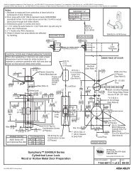
Profile Series v.<strong>S1</strong> PoE <strong>Cylindrical</strong> <strong>Lock</strong>A Frame Harness <strong>Installation</strong>Supplied by CICut end / ceiling-side PoE harness:Suggested installation of components and wire harness supplied by McKinney:B-SpliceCrimp ConnectorTIA-568-B Standard WiringCeiling24AWGStrandedWire forEarthGroundinside15' FrameHarnessFrame-SideHarnessAssembly(15' length)RJ45-MCable: CAT 5e or higher24 AWG shielded, 100ohm1234Pair Number Wire PIN1 White/Blue2 White/Orange3 White/Green4 White/BrownWhite/Blue 5Blue 4White/Orange 1Orange 2White/Green 3Green 6White/Brown 7Brown 8Do not confuse pair numbers with pin numbers. A pair number is used forreference only (e.g.: 10Base-T Ethernet uses pairs 2 & 3). The pin numbersindicate actual physical locations on the plug and jack.Hinge side of PoE harness:567 81. Feed cut end of harness into hole on hinge-side through single access hole.2. Push one of the connectors back through hole and feed into separateaccess hole.BCabledrain wireconcealedin shrinktubingFrameMolex-MPoE Data Hinge4-pin M6-pin M4-pin F6-pin FEach of the hinge-side harness connectors should end up threaded througha different access hole and matched to the same size pin connector fromthe door harness:• 4-pin male Molex connector.• 6-pin male Molex connector with ground wire.Drain WirePoE Hinge (Patent Pending)Hinge-side harness connectors:• 4-pin male molex connector• 6-pin male molex connector with ground wire<strong>Lock</strong>-side harness connectors:• Ring terminal• (2) 4-pin connectors• 4-pin Molex connector• 4-pin connectorNotes:• Connectors go on only one way. They cannot beplugged to incorrect position.• Do not force and do not offset connectors.• Be sure they are completely seated (flush).Copyright © 2011, Sargent Manufacturing Company, an ASSA ABLOY Group company. All rights reserved.Reproductions in whole or in part without express written permission of Sargent Manufacturing Company is prohibited.A7763B 502/11/11
Profile Series v.<strong>S1</strong> PoE <strong>Cylindrical</strong> <strong>Lock</strong><strong>Installation</strong> Wiring (Continued)CPoE Door HarnessOrder of installation may vary. Refer to appropriate sections for instructions.1. Prop door open.2. Tape the two lock-side 4-pin connectors to the ring terminal.3. Using the ring terminal, carefully fish the assembly through the door channel to the lock.4. Remove tape from ring terminal and door harness connectors.Hinge-side harness connectors:• 4-pin male Molex connector• 6-pin male Molex connector with ground wire<strong>Lock</strong>-side harness connectors:• Ring terminal• (2) 4-pin connectors4-pin F4-PinCopyright © 2011, Sargent Manufacturing Company, an ASSA ABLOY Group company. All rights reserved.Reproductions in whole or in part without express written permission of Sargent Manufacturing Company is prohibited.6-pin MDrain WireCable: CAT 5e,26 AWG stranded,shielded, 100ohm4-PinGroundRing Terminal Securedto <strong>Lock</strong> Mounting PlatePoE <strong>Lock</strong>02/11/116 A7763B
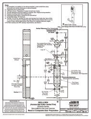
Profile Series v.<strong>S1</strong> PoE <strong>Cylindrical</strong> <strong>Lock</strong>DDoor Position Switch1. Prep door according to proper template (Fig. D1).2. Insert connector end of DPS through the raceway on the latchedge of the door (Fig. D2).Note: Only use collar when installing in a metal door.3. To insert DPS, push wires through raceway toward lock prep.4. Push DPS firmly into place by hand.IMPORTANT: DO NOT TAP SWITCH WITH ANY TOOL.5. To connect DPS to lock controller per diagram, refer to the wiringinstruction sections in the <strong>Installation</strong> <strong>Instructions</strong> section.FrameInside of DoorRacewayDim 1Dim 2(See template)Door PositionSwitch HoleCollar is used onlywith metal doors.Verticalof StrikeDoor PositionSwitch (DPS)Fig. D2Wood FrameHorizontalof StrikeMetal FrameDim 1 3/8” 3/4”Fig. D1Strike for <strong>Cylindrical</strong> <strong>Lock</strong>Copyright © 2011, Sargent Manufacturing Company, an ASSA ABLOY Group company. All rights reserved.Reproductions in whole or in part without express written permission of Sargent Manufacturing Company is prohibited.A7763B 702/11/11
Copyright © 2011, Sargent Manufacturing Company, an ASSA ABLOY Group company. All rights reserved.Reproductions in whole or in part without express written permission of Sargent Manufacturing Company is prohibited.02/11/11Profile Series v.<strong>S1</strong> PoE <strong>Cylindrical</strong> <strong>Lock</strong>8 A7763BEPoE <strong>Lock</strong> WiringUnusedRX COM (WHITE)UnusedUnusedRX NC (GREEN)UnusedMotor B (BLACK)Motor A (RED)TB2E1TB1<strong>Control</strong>ler Board Connectors .(Inside Escutcheon)J7, J4JST Connectors(From Hinge)Ground Ring Terminal(From Hinge to Top Left Escutcheon Screw)D10JP3C5C37U4D9U1R24R4C10R21TP8C31L1U2D7DN1C12R8D2R5C4J7C16C34U3R14JP4C18R22C6Q1C11TP1TP2J5R10D11DN2T2C1TP3R3D5R1TP4C2TP7C32TP5R7TP6C9R13C35R9C3R2D4C8R23TP9R12 C19R25C15R11C20DN3D6C13C7D1C33J2R6D3C14T1J3C36C17MTG2MTG3MTG4MTG1J6C21J8R15R16J4D10JP3C5C37U4D9U1R24R4C10R21TP8C31L1U2D7DN1C12R8D2R5C4J7C16C34U3R14JP4C18R22C6Q1C11TP1TP2J5R10D11DN2T2C1TP3R3D5R1TP4C2TP7C32TP5R7TP6C9R13C35R9C3R2D4C8R23TP9R12 C19R25C15R11C20DN3D6C13C7D1C33J2R6D3C14T1J3C36C17MTG2MTG3MTG4MTG1J6C21J8R15R16J4D10JP3C5C37U4D9U1R24R4C10R21TP8C31L1U2D7DN1C12R8D2R5C4J7C16C34U3R14JP4C18R22C6Q1C11TP1TP2J5R10D11DN2T2C1TP3R3D5R1TP4C2TP7C32TP5R7TP6C9R13C35R9C3R2D4C8R23TP9R12C19R25C15R11C20DN3D6C13C7D1C33J2R6D3C14T1J3C36C17MTG2MTG3MTG4MTG1J6C21J8R15R16J4D10JP3C5C37U4D9U1R24R4C10R21TP8C31L1U2D7DN1C12R8D2R5C4J7C16C34U3R14JP4C18R22C6Q1C11TP1TP2J5R10D11DN2T2C1TP3R3D5R1TP4C2TP7C32TP5R7TP6C9R13C35R9C3R2D4C8R23TP9R12 C19R25C15R11C20DN3D6C13C7D1C33J2R6D3C14T1J3C36C17MTG2MTG3MTG4MTG1J6C21J8R15R16J4D10JP3C5C37U4D9U1R24R4C10R21TP8C31L1U2D7DN1C12R8D2R5C4J7C16C34U3R14JP4C18R22C6Q1C11TP1TP2J5R10D11DN2T2C1TP3R3D5R1TP4C2TP7C32TP5R7TP6C9R13C35R9C3R2D4C8R23TP9R12C19R25C15R11C20DN3D6C13C7D1C33J2R6D3C14T1J3C36C17MTG2MTG3MTG4MTG1J6C21J8R15R16J4D10JP3C5C37U4D9U1R24R4C10R21TP8C31L1U2D7DN1C12R8D2R5C4J7C16C34U3R14JP4C18R22C6Q1C11TP1TP2J5R10D11DN2T2C1TP3R3D5R1TP4C2TP7C32TP5R7TP6C9R13C35R9C3R2D4C8R23TP9R12 C19R25C15R11C20DN3D6C13C7D1C33J2R6D3C14T1J3C36C17MTG2MTG3MTG4MTG1J6C21J8R15R16J48765432112345678D10JP3C5C37U4D9U1R24R4C10R21TP8C31L1U2D7DN1C12R8D2R5C4J7C16C34U3R14JP4C18R22C6Q1C11TP1TP2J5R10D11DN2T2C1TP3R3D5R1TP4C2TP7C32TP5R7TP6C9R13C35R9C3R2D4C8R23TP9R12C19R25C15R11C20DN3D6C13C7D1C33J2R6D3C14T1J3C36C17MTG2MTG3MTG4MTG1J6C21J8R15R16J4D10JP3C5C37U4D9U1R24R4C10R21TP8C31L1U2D7DN1C12R8D2R5C4J7C16C34U3R14JP4C18R22C6Q1C11TP1TP2J5R10D11DN2T2C1TP3R3D5R1TP4C2TP7C32TP5R7TP6C9R13C35R9C3R2D4C8R23TP9R12 C19R25C15R11C20DN3D6C13C7D1C33J2R6D3C14T1J3C36C17MTG2MTG3MTG4MTG1J6C21J8R15R16J4D10JP3C5C37U4D9U1R24R4C10R21TP8C31L1U2D7DN1C12R8D2R5C4J7C16C34U3R14JP4C18R22C6Q1C11TP1TP2J5R10D11DN2T2C1TP3R3D5R1TP4C2TP7C32TP5R7TP6C9R13C35R9C3R2D4C8R23TP9R12C19R25C15R11C20DN3D6C13C7D1C33J2R6D3C14T1J3C36C17MTG2MTG3MTG4MTG1J6C21J8R15R16J4D10JP3C5C37U4D9U1R24R4C10R21TP8C31L1U2D7DN1C12R8D2R5C4J7C16C34U3R14JP4C18R22C6Q1C11TP1TP2J5R10D11DN2T2C1TP3R3D5R1TP4C2TP7C32TP5R7TP6C9R13C35R9C3R2D4C8R23TP9R12 C19R25C15R11C20DN3D6C13C7D1C33J2R6D3C14T1J3C36C17MTG2MTG3MTG4MTG1J6C21J8R15R16J4Ground Screw to Connector to E1From<strong>Lock</strong>(+) 9VDC (RED)(-) (BLACK)AX/DPS NC (PINK)AX/DPS COM (VIOLET)UnusedUnusedUnusedEGND (GREEN)DPSCOM (VIOLET)NC (PINK)TB2 E1 TB1 PowerFromOutsideEscutcheon
Profile Series v.<strong>S1</strong> PoE <strong>Cylindrical</strong> <strong>Lock</strong>7 Parts Breakdown 125 kHz Prox and 13.56 MHz iCLASS9978461095329111116112131415Copyright © 2011, Sargent Manufacturing Company, an ASSA ABLOY Group company. All rights reserved.Reproductions in whole or in part without express written permission of Sargent Manufacturing Company is prohibited.A7763B 902/11/11
Profile Series v.<strong>S1</strong> PoE <strong>Cylindrical</strong> <strong>Lock</strong>Parts Breakdown 125 kHz Prox and 13.56 MHz iCLASS, continuedITEM PART NO. DESCRIPTION REQ’D1 Outside Lever Reference <strong>Cylindrical</strong>/10 Line Catalog For Available Levers 12 Inside Lever Reference <strong>Cylindrical</strong>/10 Line Catalog For Available Levers 13 10-3016 Outside Escutcheon Assembly 14 10-3015 Inside Escutcheon Assembly 15 52-2431 125kHz Prox Only Bezel Assembly (PA) 152-2432 Keypad & 125kHz Prox Bezel Assembly (PK)OR52-4420 13.56MHz iCLASS Only Bezel Assembly (<strong>S1</strong>-IA)13.56 mHz reader assembly ships configured for PoE/Hardpower use.52-4421 Keypad & 13.56 MHz iCLASS Bezel Assembly (<strong>S1</strong>-IK)13.56 mHz reader assembly ships configured for PoE/Hardpower use.Copyright © 2011, Sargent Manufacturing Company, an ASSA ABLOY Group company. All rights reserved.Reproductions in whole or in part without express written permission of Sargent Manufacturing Company is prohibited.6 52-4424 <strong>S1</strong> <strong>Control</strong>ler Assembly (Single Pulse); ships (Double Pulse) when ordered seperately and mustbe field configured to 10G77 (Single Pulse).7 52-3855 Battery Cover Assembly 18 01-1212 Security Screw 19 52-2526 Screw Pack -Specify Finish1(Includes: Fire Stop Plate, Trim Mounting Screws and Security Allen Wrench)10 52-3893 Door Position Switch 111 10-3048 Inside Rose Assembly 112 10-3049 Outside Rose Assembly 113 10-3409 Motorized RX <strong>Cylindrical</strong> <strong>Lock</strong> Assembly for options 10, 21, 22, 30, SC, SE, VA, VS (non handed)10-3414 Motorized RX <strong>Cylindrical</strong> <strong>Lock</strong> Assembly for options 60, 63, 64 (non handed)110-3419 Motorized RX <strong>Cylindrical</strong> <strong>Lock</strong> Assembly for options 70, 72, 65-73, 65-73-7P (non handed)10-3439 Motorized RX <strong>Cylindrical</strong> <strong>Lock</strong> Assembly for options 80, 82, 82 F1 (non handed)10-3440 Motorized RX <strong>Cylindrical</strong> <strong>Lock</strong> Assembly for options SF (non handed)14 10-2000 2-3/4 Backset Latch (Standard) 115 10-2052 <strong>Cylindrical</strong> Screw Pack - Specify Finish1(Includes: Strike and Latch Screws, Push Pin Tool, and Strike Box)16 Consult Factory 10 Line Cylinder 1102/11/1110 A7763B
Profile Series v.<strong>S1</strong> PoE <strong>Cylindrical</strong> <strong>Lock</strong>8<strong>Installation</strong> <strong>Instructions</strong>Step #1 – Door PreparationA. Verify Hand and Bevel of DoorStand on outside/locked side of door when determining the door handLHLeft HandHinges LeftOpen InwardLHRBLeft HandReverse BevelHinges LeftOpen OutwardRHRight HandHinges RightOpen InwardRHRBRight HandReverse BevelHinges RightOpen OutwardB. Prepare DoorFig. 1A• Prior to installation, all holes must be free of burrs, debris and sharp edges.• If doors are not properly reinforced per ANSI 115.2, commercially available reinforcementsshould be installed.• Prepare door according to appropriate template (refer to web site www.intelligentopenings.com):Door Manufacturer template: 4632.RacewayRibbon Cable Hole(<strong>Control</strong>ler to Keypad)Lever Handle HoleInside of DoorThrough-bolt HoleDPSPre-drilledTap Holes<strong>Cylindrical</strong>Pocket andLatch HoleOutside of DoorThrough-bolt HoleRibbon Cable Hole(<strong>Control</strong>ler to Keypad)Lever Handle HoleThrough-bolt HoleCopyright © 2011, Sargent Manufacturing Company, an ASSA ABLOY Group company. All rights reserved.Reproductions in whole or in part without express written permission of Sargent Manufacturing Company is prohibited.Fig. 1B Wood Door PreparationA7763B 1102/11/11
Profile Series v.<strong>S1</strong> PoE <strong>Cylindrical</strong> <strong>Lock</strong>Step #2 – Install StrikeInstall strike in the door frame (Fig.2A).Centerline of LatchFront and Strike(2) #8-32 x 3/4"Latch ScrewsOutside of DoorFig. 2AStep #3 - Install Latchbolt1. Install latch with beveled bolt facing the strike.2. Attach with two screws but DO NOT tightencompletely at this time.IMPORTANT: Latch bevel must match door bevel anddeadlocking latch must stop on strike when door is closed.StrikeDeadlocking LatchFig. 3BCopyright © 2011, Sargent Manufacturing Company, an ASSA ABLOY Group company. All rights reserved.Reproductions in whole or in part without express written permission of Sargent Manufacturing Company is prohibited.Step #4 – Door OptionsA. Fire Stop Plate (P/N 52-0033)Fire-rated doors require a fire stop plate onthe outside of the door (Fig. 4A).1. Drill (2) 1/8" x 1-1/4" deep holes in thedoor if not already present.Refer to template for fire-stopprep locations.2. Attach with flap up andout using (2) #8 x 1/2”self-tapping screws forwood and metal doors.B. Weather Conduit (52-2847)Install weather conduit onNON FIRE-RATED exterior doors only (Fig. 4B).1. Carefully insert the weather conduit into theribbon cable hole on the inside of the door.2. Place the O-ring around the weather conduiton the outside and up against the door (Fig. 4C)Fig. 4AOutside of Door(2) 1/8” DiameterHoles RequiredFire Stop Plate(2) #8 Self-TappingScrews for Woodand Metal Doors(2) Through-bolt HolesRibbon Cable HoleO-RingFig. 3AFig.4C02/11/1112 A7763BFig.4BOutside of Door
Profile Series v.<strong>S1</strong> PoE <strong>Cylindrical</strong> <strong>Lock</strong>Step #5 – <strong>Lock</strong> AdjustmentA. <strong>Lock</strong> Preset:• <strong>Lock</strong> body holes: 12 and 6 o’clock (Fig. 5A).• Door thickness: 1-3/4” thick. Refer to adjustmentsbelow for other door conditions (Fig. 5B Detail).B. Through-Bolt and Door Thickness Adjustment:1. Remove outside lever, scalp, and spacer bushing (Fig. 5A).2. Rotate mounting plate to either align with through-bolt holesin door, or adjust for proper door thickness (Fig. 5A and 5B).Refer to markings on through-bolt post.3. Re-install spacer bushing to align with back of lever,scalp, and lever.Through-bolt HoleOutside of Door1-3/4” Thick Doors2” Thick DoorsFig. 5ASpacer BushingRotate to matchthrough-boltholes in doorFig. 5B DetailStep #6 – Outside LeverA. How To Remove Outside Lever1. Insert key, rotate 45° clockwise and hold.2. Depress lever retainer with push pin tool (provided).B. How To Change Cylinder (if Necessary)1. With outside lever in hand, use standardpliers to pull out cylinder retainer.2. Remove key and cylinder from lever.3. Insert new cylinder.4. Secure by pressing cylinder retainer flushwith the lever.Washers required for30- prefix (10 Line Lever)to accept Schlage cylinder(no cylinder provided)Push Pin ToolCylinderSpacerCylinderRetainerCylinderFig. 6BFig. 6A˚OutsideLeverKeyA7763B 13Copyright © 2011, Sargent Manufacturing Company, an ASSA ABLOY Group company. All rights reserved.Reproductions in whole or in part without express written permission of Sargent Manufacturing Company is prohibited.02/11/11
Profile Series v.<strong>S1</strong> PoE <strong>Cylindrical</strong> <strong>Lock</strong>Step #6 - Install <strong>Lock</strong>1. Feed wires into the lock body hole from outside of door (Fig.6A).2. Slide lock body into cross-bore hole from outside (locked side)of the door (Fig. 6B).3. <strong>Lock</strong> body must engage both the latch unit prongsand tail piece (Fig. 6C Detail).IMPORTANT:• Latchbolt screws remain partially tightened.• Door must remain open during installation. Use door stop.• <strong>Lock</strong> body must be centered in the door.Outside<strong>Cylindrical</strong><strong>Lock</strong>Body1Outside of DoorWire Harness(From <strong>Lock</strong> Body)DPSFig. 6ACopyright © 2011, Sargent Manufacturing Company, an ASSA ABLOY Group company. All rights reserved.Reproductions in whole or in part without express written permission of Sargent Manufacturing Company is prohibited.Inside3Fig. 6B DetailLatchbolt Screws(Partially Tightened)Step #7 – Secure the <strong>Lock</strong> to the Door1A. For wood door: Feed wires up through the routedchannel (Fig. 7A).1B. For metal door: Feed wires and connector throughinside of door (not shown).2. Slide inside rose assembly and spacer bushingover lock body and secure with (2) #10-32x1-1/4" through-bolts.3. Secure with (2) additional #6 x 3/4" self-tapping screws.Note: Refer to preceding page to remove outside lever.4. Tighten latch screws securely.2Inside of DoorFig. 6C Detail3Fig. 7A02/11/1114 A7763B
Profile Series v.<strong>S1</strong> PoE <strong>Cylindrical</strong> <strong>Lock</strong>Step #8 – Install Gasket and Outside EscutcheonFor exterior applications, use weatherseal gasket between escutcheon and outside doorsurface.To apply weatherseal gasket:1. Carefully remove the backing from the gasket (Fig. 8A).2A. For fire rated doors: Feed ribbon cable with connector and ground wire fromoutside of door through weather seal gasket and fire stop plate (Fig. 8A).2B. For non-fire rated doors: Feed ribbon cable with connectorand ground wire from outside of door through weather seal gasket (if used) andweather conduit (if used; not shown).Note: Install ribbon cable with cable exiting down.3. Apply gasket to escutcheon:a. Starting in one place, press the adhesive sideof the gasket firmly against the escutcheon.b. Work around the escutcheon, pressing thesticky side of the gasket firmly against theescutcheon edge.c. The gasket should be aligned so that all edgesof the escutcheon are covered.4. Place the outside escutcheon against, whiledirecting mounting posts through the door.KeypadRibbonCableFig. 8AGasketAntenna(iCLASS)OnlyGroundWire(E1)Cylinder spacerOutside of DoorCopyright © 2011, Sargent Manufacturing Company, an ASSA ABLOY Group company. All rights reserved.Reproductions in whole or in part without express written permission of Sargent Manufacturing Company is prohibited.A7763B 1502/11/11
Profile Series v.<strong>S1</strong> PoE <strong>Cylindrical</strong> <strong>Lock</strong>Step #11 – Ciruit Board WiringBefore installing escutcheon, route raceway cables and ground attach tofront of circuit board.Turn the controller assembly over:1. Route the raceway connectors over the top of the controller assemblyand plug into the front of the circuit board (side that faces out whenmounted (J7, J4; Fig. 12A).2. Route the 2 ground ring terminals, one from the lock and the otherfrom the hinge wiring, over the top of the controller assembly and connectboth to the top escutcheon screw.Note: Connectors go on only one way.Do not offset connectors and make sure they are completely seated.GroundRingTerminalInside of DoorStep #12 – Install Inside Escutcheon1. Gently fold the excess ribbon connector and ground wire into thetop hole, JST connectors and ground wire into offset middle hole,and mortise and AX/DPS wires into bottom hole, being careful notto pinch wires (Fig. 12A).2. Insert (2) #8-32 x 1-1/4” screws through inside escutcheon andthread into outside escutcheon (Fig. 12B).3. Straighten escutcheons and check that latch screwsare tightened securely.Fig. 11AInside of DoorLatch ScrewsFig. 12BCopyright © 2011, Sargent Manufacturing Company, an ASSA ABLOY Group company. All rights reserved.Reproductions in whole or in part without express written permission of Sargent Manufacturing Company is prohibited.Fig. 12AA7763B 1702/11/11
Profile Series v.<strong>S1</strong> PoE <strong>Cylindrical</strong> <strong>Lock</strong>9Operational Check1. Insert key into cylinder and rotate.There should be no friction against lock case, wire harness or any other obstructions.2. Check that the key retracts the latch.The key should rotate freely.3. Use a prox 125 kHz or 13.56 MHz iCLASS credential, or keypad PIN code set up with theNetwork and <strong>Lock</strong> Configuration Tool to unlock outside lever and retract latch.Refer to Network <strong>Lock</strong> and Configuration Tool user manual (WFMN1D) for information on howto configure and program v.<strong>S1</strong> locks.Copyright © 2011, Sargent Manufacturing Company, an ASSA ABLOY Group company. All rights reserved.Reproductions in whole or in part without express written permission of Sargent Manufacturing Company is prohibited.A7763B 1902/11/11
SARGENT Manufacturing100 Sargent DriveNew Haven, CT 06511 USA800-810-WIRE (9473) • www.sargentlock.comFounded in the early 1800s, SARGENT® is a market leader in locksets, cylinders, door closers, exit devices,electro-mechanical products and access control systems for new construction, renovation, and replacement applications.The company’s customer base includes commercial construction, institutional, and industrial markets.Copyright © 2011, Sargent Manufacturing Company, an ASSA ABLOY Group company. All rights reserved.Reproduction in whole or in part without the express written permission of Sargent Manufacturing Company is prohibited.ASSA ABLOY is the global leader in door opening solutions, dedicated tosatisfying end-user needs for security, safety and convenience.A7763B-02/11