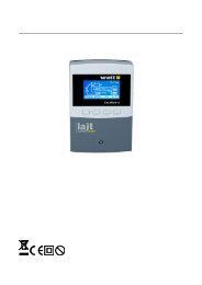
ST-460 - Watt
ST-460 - Watt
ST-460 - Watt
You also want an ePaper? Increase the reach of your titles
YUMPU automatically turns print PDFs into web optimized ePapers that Google loves.
Tech- 1 -
<strong>ST</strong> – <strong>460</strong> operation manualDeclaration of Conformity No. 53/2012Hereby, we declare under sole responsibility that the<strong>ST</strong>-<strong>460</strong> 230V 50Hz thermoregulator manufactured by TECH,headquartered in Wieprz 1047A, 34-122 Wieprz, is compliantwith the Regulation by the Ministry of Economy. (Journal ofLaws Dz.U. 155 Item 1089) of July 21, 2007 implementingprovisions of the Low Voltage Directive (LVD) 2006/95/EC ofJanuary 16, 2007.The <strong>ST</strong>-<strong>460</strong> controller has been tested for electromagneticcompatibility (EMC) with optimal loads applied.For compliance assessment, harmonized standards wereused:PN-EN 60730-2-9:2006.- 2 -
TechATTENTION!High voltage!Make sure the regulator is disconnected from themains before working on the power supply (cableconnections, device installation, etc.)!All connection works must only be carried out byqualified electricians.Before activating the controller, measure themotor resetting efficiency and inspect wireinsulation.- 3 -
<strong>ST</strong> – <strong>460</strong> operation manual- 4 -
<strong>ST</strong> – <strong>460</strong> operation manualIII.User menuIII.a) HompageDuring normal operation of the regulator, the graphic displayshows Homepage, on which, in addition to the diagram of the chosensystem, the following are displayed:-operation mode (or alarm type),-current hour,-collector temperature,-current heat container temperature,-temperature of all additional sensors depending on the configuration.On the navigation bar, the following graphic elements are displayed:ICON DESCRIPTION ICON DESCRIPTIONAutomaticoperationmodeCollectordefrosting modeCollector overheating(alarm mode)Sensor damage(alarm mode)Holiday mode- 6 -
<strong>ST</strong> – <strong>460</strong> operation manualtemperature on the collector increases above the temperature of thetank by the value of the solar pump activation delta.When the pump deactivates after reaching the set temperature,its reactivation will take place if the temperature falls below the setvalue by the value of the tank hysteresis (the hysteresis value is setin: SERVICE MENU > Accumulation tank > Tank hysteresis)2. Collector defrosting.Using this function, you can manually activate the collector pumpin order to melt snow on the solar panels. After activation, this mode isactive for the time specified by the user, and then the controller returnsback to the automatic operation (the defrosting time is set in: SERVICEMENU > Solar collector > Defrost time). The function can be switched offmanually after a shorter operation time by selecting a different operationmode.3. Holiday mode.After holiday mode activation, the pump works when thetemperature of the collector increases up to the overheating temperaturevalues (SERVICE MENU > Solar collector > Overheating temperature)reduced by the value of the Holiday delta parameter (SERVICE MENU >Accumulation tank > Holiday delta), or when the collector temperature islower than the temperature of the tank. When this condition is met, thepump activates to cool down the collector (or the container) Deactivationof the pump takes place after reducing the temperature by 5°C. Such apump operation algorithm in the holiday mode allows for maximumenergy saving.4. Manual operation.In this function, in order to control the installation devices, theuser can manually (by pressing the selected device icon) activate anddeactivate:-solar pump,-second solar pump or switching valve,-additional device (voltage-free contact e.g.. for firing up the pelletboiler)III.c) TimerIn this function, the user sets current time, according to which theregulator will be operating.- 8 -
III.d) Internet ModuleTechNOTE This type of controlling is possible after purchasing additionalcontrol module <strong>ST</strong>-500, which is not provided with the standardversion of the controller, and connecting it to the controller.The Internet Module is a device permitting remote control of thecollector operation over the Internet or local network. On the homecomputer screen, the user controls the status of all the solarinstallation equipment and the operation of each device is presentedin the form of an animation.After activating the Internet module and selecting the DHCPoption, the controller will automatically download parameters from thelocal network such as: IP address, IP Mask, Gateway Address andDNS Address. In the case of any problems with downloading thenetwork parameters, it is possible to set these parameters manually.The method of obtaining the local network parameters has beendescribed in the Internet module manual.The Resetuj hasło modułu function may be used when the userhas changed on the login page the factory user's password for his ownpassword. When a new password is lost, it is possible to return to thefactory password after resetting the module password.III.e) GSMNOTE This type of controlling is possible after purchasing additionalcontrol module <strong>ST</strong>-65, which is not provided with the standardversion of the controller, and connecting it to the controller.The GSM module is an optional device cooperating with thecollector controller, allowing remote control of the collector operationwith the use of a mobile phone. The user is notified with a textmessage on each test alert of the solar installation controller and bysending an appropriate SMS message at any time, he receives areturn message with the information on the current temperature of allsensors.The <strong>ST</strong> - 65 module can operate also independently from thecollector controller. It has two inputs with temperature sensors, singlecontact input for use in any configuration (detecting shortcircuit/opening of contacts) and one controlled output (e.g. possibilityto connect additional contactor to control any electrical circuit).When any sensor temperature reaches the set maximum or- 9 -
<strong>ST</strong> – <strong>460</strong> operation manualminimum temperature, the module will automatically send a textmessage with such information. It is similar in the case of a short-circuitor opening of contact input, which may be used e.g. for simple protectionof property.III.f) Chart PreviewThis function allows the user to see charts describing thefollowing parameters:•total energy obtained as a result of the solar collector operation,•total pump operation time,•average pump operation time•average differential temperature between the collector and thetank,•average pump rotations.The charts and the average values show particular parameters overa specified time period: Daily, Weekly and Monthly. Pressing a specificchart bar (e.g. hour in the case of a weekly chart) shows particularvalues at the bottom of the screen. For each time interval, specificationof particular values is added.III.g) HighlightingThe parameter regulates the level of brightness of the display afterit turns blank.III.h) LanguageThe user can select the language version of the controller.III.i) InformationSelecting this option displays the logo of the controller'smanufacturer and the current program version.III.j) Factory settingsThe regulator is pre-configured for operation. However, it should beadjusted for own needs. Return to the factory settings is possible atany moment. Activating the factory settings option cancels all theuser's controller settings and replaces them with the settings saved bythe controller manufacturer. From that moment, own controller- 10 -
parameters may be set once again.IV. SERVICE MENUTechAIn order to enter the maintenance settings, select the SERVICEMENU option and then select code 538 and confirm. In order to returnback to the main window display (to leave the SERVICE MENU), pressthe leave butto , by pressing a couple of times or waiting about 30seconds (then the device automatically leaves the maintenance mode).IV.a) Scheme SelectionFor the solar installation to operate correctly, appropriate selectionof the proper installation scheme ( SERVICE MENU > IN<strong>ST</strong>ALLATIONSCHEME) and the suitable additional options configuration of the chosensystem ( SERVICE MENU > IN<strong>ST</strong>ALLATION OPTIONS) are necessary.ATTENTION On the following installation diagrams, at the sensors'temperatures, the number of a given sensor is located. Connection ofthe respective sensors in proper places should be implemented accordingto this numeration (in order from the left):(1) – collector sensor (PT1000), (2) – container sensor (PT1000),(3) – additional sensor 1 (PT1000), (4) – additional sensor 2 (PT1000)IV.a.1) Scheme 1/10Installation 1/10 handles:➔ collector pump,➔ accumulation tank,➔ one direction of collectors location,➔ additional peripherals.Installation sensors:➔ collector sensor,➔ accumulation tank sensor.- 11 -
<strong>ST</strong> – <strong>460</strong> operation manualIV.a.2) Scheme 2/10Installation 2/10 handles:➔ collector pump,➔ switching valve,➔ accumulation tank,➔ one direction of collectors location,➔ additional peripherals.Installation sensors:➔ collector sensor,➔ two accumulation tank sensors.Additional installation options:➔valve hysteresisFirst, the tank additionally heats itself up in the upper part (where theinlet of warm service water is located) and after further heating up thispart of the tank, a valve switches the circulation to the lower part of thetank. Re-switching the valve will take place after cooling down thepriority (upper) part of the tank below the set value by the valvehysteresis value (it is the differential temperature of both parts of thetank)➔Maximum heating time Z2After switching the circulation to the lower part of the tank, thisparameter determines how long it will be heated (if conditions ofswitching to the upper circulation haven't been met yet)➔Oscillation pause➔After maximum heating time Z2 (of the bottom part of thetank)expires, oscillation pause takes place (the pump is deactivated),ensuring temperature stabilization. If the upper part temperaturesufficiently drops during such a pause, the valve will switch. Otherwise,the Z2 maximum heating time cycle and the oscillation pause arerepeated.IV.a.3) Scheme 3/10- 12 -Installation 3/10 handles:➔ two collector pumps (the pumps operateindependently, each by its own circulation),➔ accumulation tank,➔ two directions of collectors location,➔ additional peripherals.Installation sensors:➔ two collector sensors,➔ accumulation tank sensor.
TechNote. Setting the (SERVICE MENU > Solar collector) option of the solarcollector applies equally to the collectors situated in both directions.Additional installation options:➔ pump activation delta 2 (same as for the main pump),➔ pump deactivation delta 2 (same as for the main pump)IV.a.4) Scheme 4/10Installation 4/10 handles:➔ collector pump,➔ auxiliary pump (Pump 2),➔ accumulation tank,➔ one direction of collectors location,➔ additional peripherals.Installation sensors:➔ collector sensor,➔ two accumulation tank sensors➔ pellet boiler temperature sensor.Additional installation options:➔additional heating activation deltaIn this installation model, there is additional circulation for heatingthe tank with the use of CH (Central Heating) boiler. If the presenttemperature of the tank is lower than the preset tank temperature by atleast the set value of the activation delta (it is the difference betweenthe set temperature and the current tank temperature), the auxiliarypump (from the boiler) will activate in order to additionally heat theaccumulation tank up (provided that the boiler temperature is higherthan the tank temperature) This setting will be enabled only in hours setby the user (from, until)➔from➔until➔Energy delivery [yes/no]This scheme makes it also possible to deliver energy (e.g.. to the CHinstallation) above the set threshold temperature of the tank.➔Delivery thresholdThis scheme makes it also possible to deliver energy (e.g.. to the CHinstallation) above the set threshold temperature of the tank.➔Delivery hysteresisIt is the difference between the set delivery threshold temperaturewhen the auxiliary pump is activated) and the deactivationtemperature of this pump.- 13 -
<strong>ST</strong> – <strong>460</strong> operation manual➔Solar pump - delivery [yes/no]In this installation, it is possible to deactivate the solar pump, forexample, to cool down the container with the auxiliary pump.IV.a.5) Scheme 5/10Installation 5/10 handles:➔ collector pump,➔ switching valve,➔ two accumulative tanks,➔ one direction of collectors location,➔ additional peripherals.Installation sensors:➔ collector sensor,➔ accumulation tanks sensors.Additional installation options:➔valve hysteresisThis setting relates to the valve control while cooling the collectorsensors in the holiday or alarm mode, as well as while unfreezing. Thevalve hysteresis determines the differential temperature between thetanks at which the valve switches to the opposite tank.➔tank 2 set temperatureIf the set temperature of the first tank is reached, the valve willswitch power to the circulation of the second tank. Using this function,the user sets the set temperature for the second tank.➔maximum temperature of the 2 tankThis option is for declaring the maximum acceptable safetemperature value, up to which the second tank will be allowed to heatitself in the case of overheating the collector.➔tank 2 hysteresisAfter reaching the set temperature, the auxiliary pump deactivates.The pump will activate again after the tank temperature drops below theset value by the tank 2 hysteresis value.➔Maximum heating time Z2After switching the circulation to the other tank, this parameterdetermines how long it will be additionally heated (if conditions ofswitching to the first circulation haven't been met yet)➔Oscillation pauseAfter maximum heating time Z2, an oscillation pause takes place(the pump is deactivated), ensuring temperature stabilization. If duringsuch pause the temperature of the first tank sufficiently drops, thevalve will switch. Otherwise, the maximum heating time cycle Z2 andthe oscillation pause are repeated.- 14 -
IV.a.6) Scheme 6/10Installation 6/10 handles:➔ two collector pumps,➔ two accumulative tanks,➔ one direction of collectors location,➔ additional peripherals.Installation sensors:➔ collector sensor,➔ accumulation tanks sensors.TechAdditional installation options:➔ tank 2 set temperatureThis function is used to set the set temperature of the secondtank, after the collector 2 pump deactivates.➔ maximum temperature of the 2 tankThis option is for declaring the maximum acceptable safetemperature value, up to which the second tank will be allowed toheat itself in the case of overheating the collector.➔ tank 2 hysteresisAfter reaching the set temperature, the auxiliary pumpdeactivates. The pump will activate again after the tank temperaturedrops below the set value by the tank 2 hysteresis value.➔ operation algorithmWith this option, the user selects the operation mode of thepumps. The pumps can operate in the following modes:a) tank priority 1 - first, tank 1 is being heated (only pump 1operates) and after reaching the set temperature, pump 2 activates,additionally heating tank 2.b) parallel operation - the pumps operate independently, each inits own scope (in accordance with the settings) and both tanks arebeing heated (according to the settings) at the same time.➔ Maximum heating time Z2 (the function is enabled only when theoperation algorithm is set as the tank 1 priority ).After switching the circulation to the other tank (when the firstone reaches the setting), this parameter determines how long pump 2will work (if conditions for reactivation of the first pump haven't beenmet yet).➔ Oscillation pause (the function is only enabled when the operationalgorithm is set as the tank 1 priority).After maximum heating time Z2, oscillation pause takesplace (the pump is deactivated), ensuring temperature stabilization. Ifduring such a pause the temperature of the first tank sufficiently- 15 -
<strong>ST</strong> – <strong>460</strong> operation manualdrops, the first tank pump will be activated, (the second pump isturned off). Otherwise, the Z2 maximum heating time cycleand the oscillation pause are repeated.➔ pump 2 activation deltaThis function determines the difference between the collector andthe second tank, at which pump 2 starts to work (it is the thresholdpump activation value) If the operation algorithm is set on tank priority1, pump 2 will activate only after further heating up the first tank(when the pump 2 activation delta condition is met)➔ pump 2 deactivation deltaThis function determines the difference between the collectortemperature and the second tank temperature, at which pump 2deactivates.IV.a.7) Scheme 7/10Installation 7/10 handles:➔ collector pump,➔ second tank pump,➔ two accumulative tanks,➔ one direction of collectors location,➔ additional peripherals.Installation sensors:➔ collector sensor,➔ two main accumulation tank sensors➔ additional accumulation tank sensorAdditional installation options:➔ tank 2 set temperatureThis function is used to set the set temperature of the secondtank, after the tank 2 pump(collector pump 2) deactivates.➔ maximum temperature of the 2 tankThis option is for declaring the maximum acceptable safetemperature value, up to which the second tank will be allowed to heatitself in the case of overheating the collector.➔ tank 2 hysteresisAfter reaching the set temperature, pump 2 deactivates. Thepump will activate again after the tank temperature drops below thepreset one by the tank 2 hysteresis value.➔ operation algorithmWith this option, the user selects the operation mode of thepumps. The pumps can operate in the following modes:a) tank priority 1 - first, tank 1 is being heated (only pump 1operates ), and, after reaching the set temperature, pump 2 is activated- 16 -
Techto heat additionally the second tank. Pump 2 is deactivated afterreaching the second tank set temperature or when the temperatures ofboth tanks are equal.b) parallel operation – the pumps operate independently, each inits own scope (in accordance with the settings) and both tanks arebeing heated (according to the settings) at the same time(simultaneously)➔ pump 2 activation deltaThis function determines the difference between the tank 1temperature and the tank 2 temperature, at which pump 2 starts towork ( it is the threshold pump 2 activation value).➔ pump 2 deactivation deltaThis function determines the difference between the temperaturesof tank 1 and tank 2 at which pump 2 deactivates.IV.a.8) Scheme 8/10Installation 8/10 handles:➔ collector pump,➔ switching valve,➔ accumulation tank,➔ heat exchanger (heat receiver),➔ one direction of collectors location,➔ additional peripherals.Installation sensors:➔ collector sensor,➔ accumulation tank sensor.➔ heat exchanger sensor.In this installation, in addition to the accumulation tank, a heatreceiver is available (e.g.. CH installation), whose job is to deliverthermal energy rather than to collect it.Additional installation options:➔ valve hysteresisWhen the set temperature of the first tank is reached, the valveswitches the power supply to the heat receiver circulation. Re -switching of the valve will take place after cooling down the first tankby the valve hysteresis value (it is the differential temperature of bothtanks)➔ tank 2 set temperature- 17 -
<strong>ST</strong> – <strong>460</strong> operation manualThis function is used to set the set temperature of the secondreceiver (heat exchanger) after the collector pump deactivates.➔ maximum temperature of the 2 tankThis option is for declaring the maximum acceptable safetemperature value, up to which the second tank will be allowed to heatitself (heat receiver) in the case of overheating the collector.➔ tank 2 hysteresisAfter reaching the set heat receiver temperature, the pumpdeactivates. The pump will activate again after the heat receivertemperature drops below the set value by the tank 2 hysteresis value(provided that tank 1 is additionally heated and switching the valve tothe accumulation tank didn't occur)➔ Maximum heating time Z2After switching the circulation to heat receiver Z2 (exchanger),this parameter determines how long it will be heated (if the conditionsof switching to the first circulation have not been met yet)➔ Oscillation pauseAfter maximum heating time Z2, oscillation pause takes place ensuringtemperature stabilization. If during such a pause the temperature of thefirst tank drops sufficiently, the valve will switch. Otherwise, maximumheating time cycle Z2 and the oscillation pause are repeated.IV.a.9) Scheme 9/10Installation 9/10 handles:➔ collector pump,➔ switching valve,➔ accumulation tank,➔ double-function furnace (additional heating),➔ one direction of collectors location,➔ additional peripherals.Installation sensors:➔ collector sensor,➔ two accumulation tank sensors.This installation cooperates with a double-function furnace whichadditionally heats the circulation. If the tank temperature is too low, thevalve switches to the furnace which additionally heats water behind thetank.Additional installation options:➔ additional heating deactivationThis function is used for setting thetank temperature, below which thevalve will switch to the additional heating circulation (double - functionfurnace)- 18 -
TechIV.a.10) Scheme 10/10Installation 10/10 handles:➔ collector pump,➔ switching valve,➔ accumulation tank,➔ boiler return circulation,➔ one collectors’ location direction➔ additional peripherals.Installation sensors:➔ collector sensor,➔ two accumulation tank sensors.➔ boiler return sensor.This installation is equipped with a valve which, in the case ofexcess of hot water in the tank, will switch the boiler return circulationin order to additionally heat it up (delivering excessive heat), which willresult in solid fuel saving.Additional installation options:➔ Delivery ThresholdThe parameter is used to set the threshold tank temperature atwhich the valve will switch to additional boiler return heating.➔ Output HysteresisWhen the output threshold temperature is reached, the valve willswitch the power supply to the boiler return circulation. Re-switchingthe valve will take place after cooling down the tank by the outputhysteresis value.➔ Activation DeltaThis parameter determines the maximum difference between thetank temperature and the boiler return circulation temperature atwhich the valve switches to additional boiler return heating.➔ Deactivation DeltaThis parameter determines the minimum difference between the tanktemperature and the boiler return circulation temperature at which thevalve switches to the traditional boiler circulation (without additionalheating)IV.b) Accumulation tankIn this menu, the user sets all the parameters concerning the tank(heat container)IV.b.1) Set temperatureThis function is used to set the preset temperature in the container- 19 -
<strong>ST</strong> – <strong>460</strong> operation manualafter the collector pump deactivates.IV.b.2) Maximum tank temperature 1This option is for declaring the maximum acceptable safetemperature value, up to which the tank will be allowed to heat itself.If the collector reaches the alarm (overheating) temperature, the pumpwill be activated automatically in order to cool down the heatedcollector, regardless of the temperature set. The pump will work untilreaching the container's maximum temperature or until drop in thecollector's temperature by the alarm hysteresis value (see: SERVICEMENU > Solar collector > Alarm hysteresis)IV.b.3) Tank hysteresisUsing this function, the user declares the tank hysteresis value. Ifthe tank reaches the set temperature and the pump is deactivated, itreactivates after the tank temperature drops below the set value by thevalue of this hysteresis.IV.b.4) Manimum tank temperature 1This parameter is for declaring the minimum acceptabletemperature value, down to which the tank will be allowed to cool itself.Below this temperature, the pump will not activate in any operatingmode (apart from manual operation)IV.b.5) Cooling to the set temperatureSometimes there is a situation when the collector reaches theoverheating temperature and emergency start - up of the pump occursin order to cool it down. In this case, the tank receives heat untilexceeding the set temperature (up to the maximum temperature) Toprevent accumulation of too hot water in the container, thewychładzanie do zadanej function should be started. After activating thisoption, when the collector temperature drops below that of thecontainer, the pump will activate in order to cool down the tank until itreaches the preset temperature.IV.b.6) Holiday deltaThis function is active in the holiday operating mode only. Thisparameter determines, how many °C before reaching the collectoroverheating temperature the pump will be activated in order to cool itdown. Deactivation of the pump occurs after reducing the collectortemperature by at least 5°C.- 20 -
TechIV.b.7) Set tank 2 temperatureThis function is used to set the preset temperature in container 2after the collector pump deactivates.IV.b.8) Maximum tank 2 temperatureThis option is for declaring the maximum acceptable safetemperature value, up to which tank 2 will be allowed to heat itself.If the collector reaches the alarm (overheating) temperature, the pumpwill be activated automatically in order to cool down the heatedcollector, regardless of the temperature set. The pump will work untilreaching the container's maximum temperature or until drop in thecollector's temperature by the alarm hysteresis value (see: SERVICEMENU > Solar collector > Alarm hysteresis)IV.b.9) Tank hysteresis 2Using this function, the user declares the hysteresis value of tank 2.If the tank reaches the set temperature, and the auxiliary pumpdeactivates, it reactivates after the tank temperature drops below theset value by the value of this hysteresis.IV.b.10) Operation algorithmWith this option, the user selects the operation mode of thepumps. The pumps can operate in the following modes:a) priority of tank 1 – tank 1 is heated first (only pump 1operates), and, after reaching the set temperature, pump 2 isactivated to additionally heat tank 2.b) parallel operation - the pumps operate independently, each inits own scope (in accordance with the settings) and both tanks arebeing heated (according to the settings) at the same time.IV.c) Solar collectorIn this menu, the user sets all the parameters related to the solarcollector.IV.c.1) Overheating temperatureIt is the collector's alarm acceptable temperature at which forcedstart-up will take place in order to cool down the solar panels. Warmwater discharge will occur regardless of the preset temperature of thetank. The pump will work until its temperature falls below the alarmtemperature by the alarm hysteresis value (SERVICE MENU > Solarcollector > Alarm hysteresis) or until the tank reaches the maximum- 21 -
<strong>ST</strong> – <strong>460</strong> operation manualacceptable temperature (SERVICE MENU > Accumulation tank > Tank 1max temp.)IV.c.2) Heating minimum temperatureIt is the collector's threshold temperature below which the pumpdoes not activate. The exception are emergency modes, manualoperation or collector defrosting.IV.c.3) Alarm hysteresisUsing this function, the user declares the collector's alarmhysteresis value. If the tank reaches the alarm temperature (theoverheating temperature) and the pump activates, its deactivation willoccur when the collector's temperature decreases below the maximumtemperature by this hysteresis value.IV.c.4) Defrosting timeUsing this function, the user determines, for how long the pump will beactivated after the Collector defrosting function activation.IV.c.5) Anti-freeze temperatureOwing to different freezing temperature of the fluid in the solarinstallation, Antifrost temperature has been introduced. This parameterdetermines minimum safe temperature at which liquid glycol does notfreeze (temperature measured on the collector). In the case ofsignificant collector temperature drop (down to the value of thisparameter), the pump will be activated and will work continuously untilheating the collector up to a safe temperature. The settings range ofthis coefficient is within -50: +10°C.- 22 -
IV.d) PumpsTechIV.d.1) Regulated rotationsUsing this function, the user specifies the mode of pump operation.Fixed rotations, when the pump operates all the time with full power(always when its operation is active), or regulated rotations areavailable. When the regulated rotations are selected, the icon of thisparameter should be marked as active.IV.d.2) Maximum collector temperatureBy means of this setting, the user declares the value of thecollector's maximum alarm temperature at which the pump may bedamaged. The temperature should be set in accordance with thetechnical data of the collector involved. Due to the glycol "gelling"phenomenon at high temperatures and the risk of damaging the solarpump, after reaching the maximum alarm temperature it will bedeactivated (the regulator switches to the collector overheating mode).IV.d.3) Solar pump activation deltaThis function determines the difference between the collectortemperature and the second tank temperature at which the pump startsto work (it is the threshold pump activation value)IV.d.4) Solar pump deactivation deltaThis function determines the difference between the collectortemperature and the second tank temperature at which the pumpdeactivates (so as to avoid cooling down the tank)IV.d.5) Gear ratioThis parameter is only active, if the pump rotations are set for theregulated mode. When the conditions of pump activation are met, it isactivated initially at minimum speed (operational minimum of the solarpump). Then, the pump increases the rotations according to the settingof this ratio, which determines at how many °C of difference between thecollector temperature and the tank temperature the pump will increasethe rotations by 10%.- 23 -
<strong>ST</strong> – <strong>460</strong> operation manualIV.d.6) Circulation sampling activation thresholdThis function enables setting the Circulation Sampling ActivationThreshold - it is the minimum temperature (of the collector) for samplingfunction activation.IV.d.7) Solar pump working minimumThis parameter is only active if the pump rotations are set in theregulated mode. By means of this setting, the minimum initial pumprotations are set.IV.d.8) Solar pump working maximumThis parameter is only active if the pump rotations are set in theregulated mode. By means of this setting, the pump's maximumpercentage operation rotations are to be set.IV.d.9) Oscillation pauseAfter maximum heating time Z2, the oscillation pause takes place(the pump is deactivated), ensuring temperature stabilization. If, duringsuch a pause, the temperature of the first tank drops sufficiently, thevalve will switch. Otherwise, it repeats maximum heating cycle Z2 andthe oscillation pause.IV.d.10) Maximum heating time Z2After switching the circulation to the other tank (in the event whenthe temperature collector is too low to heat tank 1 to its settemperature), this parameter determines how long it will be heated (ifthe conditions of switching to the first circulation haven't been met yet)IV.d.11) Pump 2 deactivation deltaThis function determines the difference between the collectortemperature and the tank 2 temperature at which the pump willdeactivate (to avoid cooling down the tank)IV.d.12) Pump 2 activation deltaThis function determines the difference between the collectortemperature and the tank 2 temperature at which the pump starts towork (it is the threshold pump activation value)- 24 -
TechIV.d.13) Installation samplingThis function enables to activate or deactivate the circulation samplingintended for updating the temperature reading consisting in shortcollector pump activation (when the normal pump activation conditionsare not met) The sampling requires short activation of the pump aftergrowth of the collector temperature by at least 3°C.IV.e) PeripheriesThe user can connect an additional device and configure its settings.When there's no additional device, the None (deactivate) position shouldbe selected. Additional available devices and examples of connectionsupporting all available installation schemes are presented below.IV.e.1) Circulation pumpAfter selecting this device, set cyclic operation time and standstilltime of the pump during hours of its operation. Then, set in which hoursthe pump will be active, with the use of the "From hour..." and "Throughhour..." functions. Entering the same times (" From – Through ") willresult in the device being active throughout the whole day.You can attach an additional temperature sensor to the circulation pump,as a result of which switching this pump on and off will also bedependent on additional factor which will be temperature at thecirculation pump. Then, there will be additional parameters to set:activation threshold (if the temperature increases up to this value, thepump switches on), deactivation threshold (if the temperature dropsdown to this value, the pump switches off) and hysteresis (it determinesby how many degrees the temperature is supposed to drop to switch thecirculation pump on again)TANKSENSORCOLLECTORSENSORCollectorsensorAddit ionaldev iceNO COMTanksensorPump 2Va lveAdditionalsensor1Pum p 1Additionalsensor2P ow erFu se3,15AR<strong>ST</strong>OP BOTTOMPower~Circulationpum p~Pum p- 25 -
<strong>ST</strong> – <strong>460</strong> operation manualIV.e.2) Pellet boiler firing-upThis option is used for setting voltage-free signal to fire-up the pelletboiler. The user sets the activation delta (the difference between the settemperature and the current tank temperature), below which the controllersends the signal to ignite the boiler. Then, a time interval is selected inwhich this function will be active (by means of the "From hour..." and"Through hour..." functions). The last step is to mark whether the boilerfiring up signal will be shorted contact (icon marked) or open contact.TANKSENSORCOLLECTORSENSORCollectorsensorAddit ionaldev iceNO COMTanksensorPump 2Va lveAdditionalsensor1Pum p 1Additionalsensor2Pow erFu se3,15AR<strong>ST</strong>OP BOTTOMPowerFree voltagecontact~Pum pIV.e.3) HeaterThe heater's function is to heat the tank electrically. The principle ofoperation is similar to that in the previous case, however, the heatershould be connected by means of an additional contactor. The user setsthe activation delta (the difference between the set tank temperature andthe current tank temperature), below which the controller will activate theheater. Then, it selects a time interval in which the electric heatingfunction will be active (by means of the "From hour..." and "Throughhour..." functions).TANKSENSORCOLLECTORSENSORCollectorsensorAddit iona lde vic eNO COMTanksensorPump 2Valv eAdditionalsensor1Pum p 1Additionalsensor2Po werF use3,15AR<strong>ST</strong>OP BOTTOMPowerH E AT E Rcontactor230V~Pum p230V- 26 -
TechIV.e.4) Cooling with the HUW pumpIt is a peripheral that operates beyond time limits, that means always. Forthis peripheral to operate, sensor 4 is required (installed in the external HUWtank). The function cannot work when a scheme using all the sensors isselected. Furthermore, for it to work, tank sensor 4 is needed (in the case oftwo sensors in the tank - the upper sensor )In case of meeting the aforementioned criteria, the periphery will be activated(contact shorting) when:➔increasing temperature of the tank exceeds its maximumtemperature reduced by "the cooling activation delta" andoperates to the moment of decrease in the temperature below themaximum tank temperature reduced by "the cooling deactivationdelta" (both parameters are set in the menu)➔temperature in the tank is higher than the HUW temperature. We usethe permanent hysteresis of 3 degrees here.IV.e.5) Contact (not) compliant with the pumpThis setting determines operation of the voltage-free contact. If the"Contact compliant with the pump" icon is checked, then always when thepump is working the voltage-free contact will short (additional device willbe activated). Otherwise, (when the icon is un-checked) at each activationof the solar pump the contact is opened.IV.f) Energy calculationCorrectly entering the following values will allow for more precisemeasurement of energy being obtained.IV.f.1) FlowHere, the amount of glycol which flows through the pump per hourshould be specified.IV.f.2) Medium typeThis function allows for identification of the medium involved:ethylene glycol or propylene glycol.IV.f.3) Glycol portionSpecify the percentage concentration of glycol in water here.- 27 -
<strong>ST</strong> – <strong>460</strong> operation manualIV.f.4) OffsetThis function enables correction of the heat measurement settings.Temperature measurement takes place in the temperature installationsensor point. There is a possibility of deviations in the flow andtemperature measurement at the return from the container.IV.g) Keyboard soundThis function allows for turning acoustic signal during pressingdifferent settings on the touch screen off or on.IV.h) Factory settingsThe regulator is pre-configured for operation. However, it should beadjusted for own needs. Return to the factory settings is possible at anymoment. Activating the factory settings option cancels all the user'scontroller settings of the solar installation controller (saved in the user'smenu) and replaces them with the settings saved by the boiler'smanufacturer. From that moment, the own boiler parameters can be setagain.V. ProtectionsTo ensure maximum safe and unfailing operation, the regulator hasbeen equipped with a number of protections.1. Installation sensor protection.If one of the sensors is damaged, the following symbol will appearat the bottom of the display:At the location of the displayed damaged sensor temperature,an additional icon , informing which sensor has been disconnectedor has been damaged, will flash.To disable the alarm sound in error mode of the sensor, press anyactive icon.- 28 -
Tech2. Protection against overheating the collector .If overheating(alarm) temperature is reached, the regulatorswitchesto the so-called overheating status of the collector, on the display, thefollowing symbol appears: . The pump starts to work in order to cooldown the tank of the collector until achieving the container's maximumtemperature or until drop in the collector's temperature by the alarmhysteresis value (see: SERVICE MENU > Solar collector > Alarmhysteresis). In the case of two tanks, both are used for cooling theoverheated collector down (at the same time or successively,depending on operation algorithm setting)3. Heat container protection.In the case of collector overheating, each tank can be heated up to nomore than the set value of the maximum safe alarm temperature. Afterreaching the maximum temperature, the pump of a given tank will beshut off (in the system of two tanks with a valve, switching the circulationto the other tank will occur).3. Fuse.The regulator has a fuse tubular insert type, WT 3.15A, protecting thegrid.NOTE: do not use a fuse of a higher value. Assembling the fuse with agreater amperage can cause damage to the controllerVI. MaintenanceIn the TS-<strong>460</strong> controller, before heating season and throughout itsduration, technical condition of wires should be monitored. Check alsofastening of the controller and clean it from dust and other dirt.- 29 -
<strong>ST</strong> – <strong>460</strong> operation manualTS-<strong>460</strong> Controller Technical DataPower supply voltage 230V/50Hz +/- 10%Temperature control range8 o C : 90 o CPower consumptionmax. 5WCollector sensor temperature strength -40 o C : 180 o C (short term 200 o C)Container sensor temperature strength -25 o C : 90 o CMeasurement accuracy1 o CAmbient temperature5 o C : 50 o CLoad at each outlet1AFuse insert 3,15AVII. InstallationNOTE: Installation should be performed by a person with relevant electricalauthorizations! At that time, the device cannot be live (make sure that the plug isdisconnected from the power grid)!- 30 -
Wire ConnectionTechTOPBOTTOMCOLLECTORSENSORTANKSENSORBASIC EXAMPLEOF CONNECTIONSCollectorsensorNO COMTanksensorPump 2ValveAdditionalsensor1Pum p 1Additionalsensor2P ow erFuse3,15AR<strong>ST</strong>OP BOTTOMFree voltagecontact~WWW.TECH<strong>ST</strong>EROP u m pPowerWNIKI.PL- 31 -
<strong>ST</strong> – <strong>460</strong> operation manual- 32 -PA R A M E T E RF a c t. S e t.ACCUMULATION TANKSet temperature65 CMaximum temperature90°CMinimum temperature8°CTank HysteresisCooling down to the set value2°CyesValve 1 hysteresis15°CSet T. tank 2265°CMaximum T. tank 2 290°CTank 22Hysteresis2°COperation Algorithm3SOLAR COLLECTOR80°COverheating Temperature110 ° CMinimum additional heating temperatureAlarm Hysteresis25°C5°CDefrosting Time5minAntifreeze temperature-30°CHoliday Delta40°CPUMPS80°CSolar pump rotationsregulatedMaximum temperature130°CSolar pump activation delta8°CDeactivation Delta5°CGear Ratio3Circulation Sampling - Activation Threshold 30°CMaximum Heating Time Z2430°COscillation Pause 45°CPump 2 activation delta 58°CDeactivation Delta 2 55°CIN<strong>ST</strong>ALLATION OPTIONS80°CAdditional Heating Activation Delta 620°CEnergy Output6yesOutput Threshold760°COutput Hysteresis75°CSolar Pump Output6yesAdditional Heating Deactivation 855°CActivation Delta94°CDeactivation Delta92°CPERIPHERALS80°CCirculating pumpWorking time30minPause Time15minUse of C4noActivation Threshold0°CDeactivation Threshold40°CHysteresis2°CPellet boiler firing upActivation delta30°CActivation signal1HeaterActivation delta30°CGSM modulenoInternet ModulenoSERVICE MENUChange PIN NumberAlert Signal123456789° 40÷8560÷903÷501÷20yes, no2÷3030÷8550÷901÷20prior.tank.1 prior.tank.1/simult.40÷85100÷20080÷501÷205÷60-50÷10112yesScope of settings5÷5040÷85fixed/regulated100÷2002÷300÷71÷1010÷905÷603÷101÷300÷740÷855÷50yes/no20÷903÷30yes/no0÷803÷301÷1040÷851÷2400÷240yes/no0÷1200÷1201÷101÷500/1- the setting only applies to the following schemes: 2,5,8.- the setting only applies to the following schemes: 5,6,7,8.- the setting only applies to the following schemes: 6,7.- the setting only applies to the following schemes: 2,5,6,8.- the setting only applies to the following schemes: 3,6,7.- the setting only applies to scheme 4.- the setting only applies to the following schemes: 4,10.- the setting only applies to scheme 9.- the setting only applies to scheme 10.1÷50yes/noyes/noXXXyes/no
TechContentsI. Application .........................................................................5II. Principle of operation ..........................................................5III. User menu .......................................................................6III. a) Hompage ..................................................................6III. b) Operation mode .........................................................7III. c) Timer ........................................................................8III. d) Internet Module .........................................................9III. e) GSM .........................................................................9III. f) Chart Preview ...........................................................10III. g) Highlighting .............................................................10III. h) Language ................................................................10III. i) Information ..............................................................10III. j) Factory settings ........................................................10IV. SERVICE MENU ...............................................................11IV. a) Scheme Selection ......................................................11IV. a.1) Scheme 1/10....................................................................11IV. a.2) Scheme 2/10....................................................................12IV. a.3) Scheme 3/10....................................................................12IV. a.4) Scheme 4/10....................................................................13IV. a.5) Scheme 5/10....................................................................14IV. a.6) Scheme 6/10....................................................................15IV. a.7) Scheme 7/10....................................................................16IV. a.8) Scheme 8/10....................................................................17IV. a.9) Scheme 9/10....................................................................18IV. a.10) Scheme 10/10.................................................................19IV. b) Accumulation tank ....................................................20IV. b.1) Set temperature ...............................................................20IV. b.2) Maximum tank temperature 1 .............................................20IV. b.3) Tank hysteresis .................................................................20- 33 -
<strong>ST</strong> – <strong>460</strong> operation manualIV. b.4) Manimum tank temperature 1 .............................................20IV. b.5) Cooling to the set temperature ............................................20IV. b.6) Holiday delta ....................................................................21IV. b.7) Set tank 2 temperature .....................................................21IV. b.8) Maximum tank 2 temperature .............................................21IV. b.9) Tank hysteresis 2 ..............................................................21IV. b.10) Operation algorithm .........................................................21IV. c) Solar collector ...........................................................22IV. c.1) Overheating temperature ...................................................22IV. c.2) Minimalna temperatura dogrzewania ....................................22IV. c.3) Alarm hysteresis................................................................22IV. c.4) Defrosting time..................................................................22IV. c.5) Anti-freeze temperature......................................................22IV. d) Pumps .....................................................................23IV. d.1) Regulated rotations ...........................................................23IV. d.2) Maximum collector temperature ..........................................23IV. d.3) Solar pump activation delta ................................................23IV. d.4) Solar pump deactivation delta .............................................23IV. d.5) Gear ratio ........................................................................23IV. d.6) Circulation sampling activation threshold ..............................24IV. d.7) Solar pump working minimum .............................................24IV. d.8) Solar pump working maximum ............................................24IV. d.9) Oscillation pause ...............................................................24IV. d.10) Maximum heating time Z2 ................................................24IV. d.11) Pump 2 deactivation delta ................................................24IV. d.12) Pump 2 activation delta ...................................................24- 34 -IV. d.13) Installation sampling.........................................................25IV. e) Peripheries................................................................25IV. e.1) Circulation pump ...............................................................25IV. e.2) Pellet boiler firing-up .........................................................26IV. e.3) Heater .............................................................................26IV. e.4) Cooling with the HUW pump ...............................................27IV. e.5) Contact (not) compliant with the pump.................................27
TechIV. f) Energy calculation......................................................27IV. f.1) Flow ................................................................................27IV. f.2) Medium type .....................................................................27IV. f.3) Glycol portion.....................................................................27IV. f.4) Offset...............................................................................28IV. g) Keyboard sound.........................................................28IV. h) Factory settings ........................................................28V. Protections ......................................................................29VI. Maintenance ...................................................................29VII. Installation ....................................................................30We are committed to protecting the environment. Manufacturing electronic devicesimposes an obligation of providing for environmentally safe disposal of used electroniccomponents and devices. Hence, we have been entered into a register kept by theInspection For Environmental Protection. The crossed-out bin symbol on a productmeans that the product may not be disposed of to household waste containers.Recycling of wastes helps to protect the environment. The user is obliged to transfertheir used equipment to a collection point here all electric and electronic componentswill be recycled.- 35 -
<strong>ST</strong> – <strong>460</strong> operation manual- 36 -


