Shear
Shear
Shear

Create successful ePaper yourself
Turn your PDF publications into a flip-book with our unique Google optimized e-Paper software.
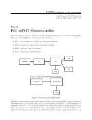
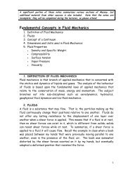
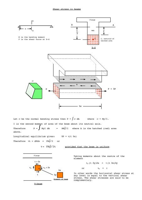
<strong>Shear</strong> stress in beamsXFlangeNAxXyWebyM is the bending momentF is the shear force at X-XCC, centroid ofhatched areaX-XστPP + δPδxLet σ be the normal bending stress then P = ∫ σ dAwhere σ = My/I.I is the second moment of area of the beam about its neutral axis.Therefore P = ∫ MyI dA = MAy/I where A is the hatched (red) areaabove.Longitudinal equilibrium gives:δP = τ(t δx)Therefore τt = dPdx = FAy/Iorτ = FAy/Itprovided that the beam is uniform.Flangeτ + δτTaking moments about the centre of theelementτ v (t δy)δx = τ (t δx)δyτ vττ v + δτδyδxElement of beamorτ v = τIn other words the horizontal shear stress atany level is equal to the vertical shearstress. The shear stresses are said to becomplementary.T-beam
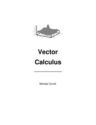
Thin-walled beamsThere is a class of cross-sections that is referred to as thin walled: I-beams, channels etc.T, flange thicknessDt, web thicknessT
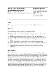
LHSH D = F e or e = HD/FRHST = H D and V = FTHeCFDHFVDiagram illustrating shear flow in a cantilever channelsection and the shear centre, C
<strong>Shear</strong> Stress Distribution in BeamsI. Thick-walled beamsQu.1The channel section shown in Fig.1 is simmply-supported over a span of 5m and carries a UDL of intensity15kN/m over its entire length. Sketch the shear stress distribution diagram at the point of maximumshearing force, and give important values. Determine the ratio of maximum shear stress to average shearstress.Answer. 3, 9.2, 9.3 N/mm 2 ; 2.421230 30Dim. in mm.75Dim. in mm.70100Fig. 1Fig. 218540Qu.2Fig.2 shows the cross-section of a beam that carries a shear force of 20kN. Determine the shear stressdistribution.Answer. 21.7, 5.2, 5.23 N/mm 2 ; 2.42Qu.3The cross-section of a beam is an isoceles triangle of base B and height H, the base being arranged in ahorizontal plane. Find the shear stress at the neutral axis due to a shear force Q acting on the crosssectionand express it in terms of the average shear stress.Answer. 8Q/(3BH) , 4τ avg /350Qu.4II. Thin-walled sectionsA beam having the cross-section shown in Fig.3 is made of metal having constant wall thickness of 1.3mm.Throught what point must the applied vertical load pass in order that there shall be no twisting of thesection? Sketch the shear stress distribution.Qu.5Determine the position of the shear centre, e, of the beams shown in Figs.4-612.74 3.092550Vet = 1.3Dim. in mm.1017.57x V kN/m250Ve25Ans. e = 37.1t = 2.5Fig.5Dim. in mm.25Ans. e = 13.9Fig.3Ve250mmAns. e = 318.35050e70120V80Fig.4Fig.6
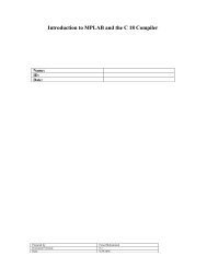
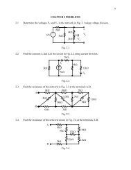
Example 1.Draw the shear stress distribution. Take F = 400kN.100Dimensions in mm50Calculate the following:NeutralAxis1. A = 7500 mm 258.3502. y = 58.3 mm3. I NA = 5.729 x 10 6 mm 425 25Use τ =FA yItCase 1 Case 2yyyCyτ =1738.9 - y 228.645Case 3yyτ =3398.9 - y 228.645NA 60.758.3116.3<strong>Shear</strong> stressdistributionin N/mm 2
Example 3.Draw the shear flow distribution. Take F = 10kN. Also find the location of theshear centre.50Dimensions in mmCalculate the following:1. A = 520 mm 250Wall thickness = 22. y = 50 mm3. INA = 966.7 x 10 3 mm 480Use f =FA yICase 11x1A 1 = 2 x 11y = 50f 1 = 1.034 x 1 N/mmCase 2x1A 2 = 160 + 2 (50 - x 2 )22y = 50 y = (50 + x 2 )/2x210000 (8000 + 50 2 - x 22 )f2 = 966.7 x 10 3= 82.8 + 1.034 (50 2 - x 22 )/10082.8H = 3312 N<strong>Shear</strong> flowdistributionin N/mm10kN10kN108.7eH10000 e = H x 100e = 33.1mm