Type WL Low Voltage Metal-Enclosed Switchgear - Siemens
Type WL Low Voltage Metal-Enclosed Switchgear - Siemens
Type WL Low Voltage Metal-Enclosed Switchgear - Siemens

You also want an ePaper? Increase the reach of your titles
YUMPU automatically turns print PDFs into web optimized ePapers that Google loves.
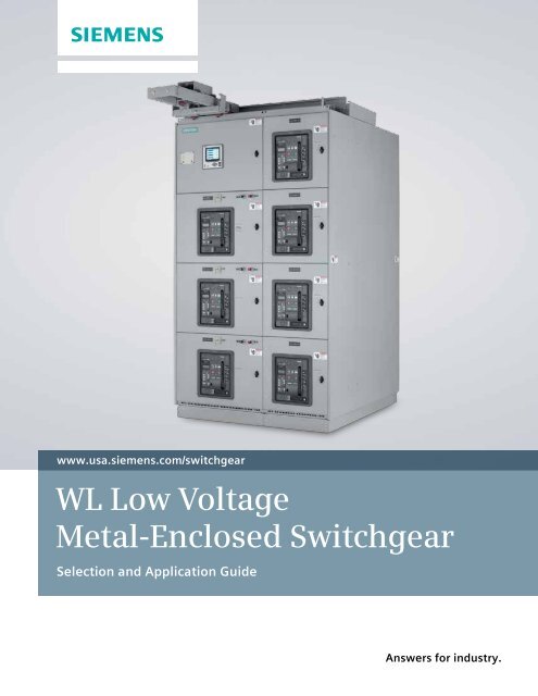
www.usa.siemens.com/switchgear<strong>WL</strong> <strong>Low</strong> <strong>Voltage</strong><strong>Metal</strong>-<strong>Enclosed</strong> <strong>Switchgear</strong>Selection and Application GuideAnswers for industry.
<strong>Type</strong> <strong>WL</strong> <strong>Low</strong> <strong>Voltage</strong> <strong>Metal</strong>-<strong>Enclosed</strong> <strong>Switchgear</strong>Table of ContentsGeneral Information............................................................................................... 2Construction Details............................................................................................ 3 - 5<strong>WL</strong> Circuit Breaker ................................................................................................ 6Electronic Trip Unit.............................................................................................. 7- 9Time/Current Characteristic Curves.............................................................................. 10 - 12Breaker Technical Data ....................................................................................... 13 - 21<strong>WL</strong> Secondary Terminal Assignments................................................................................ 22<strong>WL</strong> Communication Overview...................................................................................... 23Section Configurations ....................................................................................... 24 - 25Shipping Weights and Dimensional Information................................................................... 26 - 30VT, CPT, CT Data................................................................................................. 31Guide Form Specifications..................................................................................... 32 - 36
<strong>Type</strong> <strong>WL</strong> <strong>Low</strong> <strong>Voltage</strong> <strong>Metal</strong>-<strong>Enclosed</strong> <strong>Switchgear</strong>General Information<strong>Siemens</strong> <strong>Type</strong> <strong>WL</strong> low voltagemetal-enclosed switchgear is designed,constructed and tested to providesuperior power distribution, powermonitoring and control. At the heartof the <strong>Type</strong> <strong>WL</strong> low voltage switchgearis the World Class <strong>Siemens</strong> <strong>WL</strong> breaker.<strong>Siemens</strong> <strong>Type</strong> <strong>WL</strong> low voltageswitchgear can be utilized in thefollowing applications:• IndustrialHeavy assemblySemiconductorPetrochemicalAutomotiveBiotechPharmaceutical• InstitutionalWater treatmentAirportsUniversitiesMedical facilitiesCorrectional facilities• Critical PowerData ProcessingContinuous industrial processHospitals• Utility and co-generation• CommercialLarge office buildingsDistribution centersLarge warehousesProduct Scope:• Equipment ratings635VAC Maximum3 Phase 3 Wire,3 Phase 4 Wire50/60 Hz6000 amp maximum horizontal bus6000 amp maximum vertical bus• Enclosure optionsNEMA 1 IndoorNEMA 3R Outdoor Walk-InNEMA 3R Outdoor Non Walk-in<strong>Siemens</strong> <strong>WL</strong> breakers can be manuallyor electrically operated, fused or unfusedand are available in the following ratingdesignations – N, S, H, L, M and F. Referto tables on Page 13 for interrupt andwithstand ratings for each rating designation.Industry Standards<strong>Type</strong> <strong>WL</strong> switchgear with power circuitbreakers are designed, tested andconstructed in accordance with:• UL 1558 — <strong>Metal</strong>-<strong>Enclosed</strong> <strong>Low</strong><strong>Voltage</strong> Power Circuit Breaker<strong>Switchgear</strong>• ANSI C37.20.1 — <strong>Metal</strong>-<strong>Enclosed</strong><strong>Low</strong> <strong>Voltage</strong> Power Circuit Breaker<strong>Switchgear</strong>• ANSI C37.50 — Test Procedure for<strong>Low</strong> <strong>Voltage</strong> AC Power CircuitBreakers Used in Enclosures• ANSI C37.51 — ConformanceTesting of <strong>Metal</strong>-<strong>Enclosed</strong> <strong>Low</strong><strong>Voltage</strong> AC Power Circuit Breaker<strong>Switchgear</strong> Assemblies• NEMA SG5 - Power <strong>Switchgear</strong>Assemblies• Applicable requirements of theNational Electric Code (NEC)<strong>WL</strong> drawout circuit breakers are inaccordance with:<strong>Type</strong> <strong>WL</strong> <strong>Low</strong> <strong>Voltage</strong> <strong>Metal</strong>-<strong>Enclosed</strong> <strong>Switchgear</strong>• UL 1066 — <strong>Low</strong> <strong>Voltage</strong> AC andDC Power Circuit Breakers Usedin Enclosures• ANSI C37.13 — <strong>Low</strong> <strong>Voltage</strong> AC PowerCircuit Breakers Used in Enclosures• ANSI C37.16 — Preferred Ratings,Related Requirements, andApplication for <strong>Low</strong> <strong>Voltage</strong> PowerCircuit Breakers and AC PowerCircuit Protectors• ANSI C37.17 — Trip Devices for ACand General Purpose DC <strong>Low</strong>-<strong>Voltage</strong>Power Circuit Breakers• NEMA SG3 - <strong>Low</strong> <strong>Voltage</strong> PowerCircuit BreakersFeatures and modifications required byNEC are incorporated when the assemblyis designated as “Service Equipment.”UL ListingUnderwriters’ Laboratories listing mark(UL) is supplied for each vertical sectionprovided all devices within a verticalsection are UL Listed or UL Recognizedand suitable for the intended use. Allcircuit breaker drawout elements areUL Listed.Optional CSA compliance with cULlabeling is available.Arc ResistantOptional <strong>Type</strong> <strong>WL</strong> arc resistant low voltageswitchgear is available and is ULlisted to ANSI/IEEE C37.20.7. <strong>Type</strong> 2Barc resistant accessibility rating withmaximum internal acring short-circuitcurrent rating of 100kA @508V and85kA @ 635V.Seismic QualificationSeismic qualification to all major seismicconstruction standards (IBC, UBC, CBC,SBC, BOCA and IEEE 693) is available.2
<strong>Type</strong> <strong>WL</strong> <strong>Low</strong> <strong>Voltage</strong> <strong>Metal</strong>-<strong>Enclosed</strong> <strong>Switchgear</strong>Construction DetailsGeneralThe <strong>Siemens</strong> <strong>Type</strong> <strong>WL</strong> switchgearassembly consists of one or moremetal-enclosed vertical sections. Theend sections are designed to allowinstallation of future sections.Each vertical section consists of up tofour individually enclosed breaker orauxiliary compartments which are sizedto provide uniform height.Included in each assembly are variouscomponents such as circuit breakers,instrumentation and control equipment,transformers, relays, three-phase buswork, and all internal wiring, connectors,and other supporting equipment.In accordance with ANSI C37.20.1, themaximum temperature for parts thatare handled is 50°C. The main busmaximum temperature rise is 65°Cabove 40°C ambient. The temperaturerise of the air surrounding the cableconnection points is limited to 45°Cabove 40°C ambient.FinishDuring construction, the structural steelparts, panels, and compartments are allprepared for painting by a five-stagewash system.Standard finish color is light gray ANSI61. The standard painting process is aUL approved electrostatic powder coatpaint system utilizing a polyester powdercoat paint. The completed finish hasa nominal 2 mils dry film thickness.Assembly Construction<strong>Siemens</strong> <strong>Type</strong> <strong>WL</strong> metal-enclosed lowvoltage switchgear is constructed ofa rigid internal frame structure thatminimizes the possibility of damageduring shipment and supports multipleinstallation methods – rolling or lifting.Lifting eyes are integrated into theinternal frame design and ensurethe structural integrity of the liftingassembly is always adequate for theweight of the total structure.If requested in advance, the switchgearstructure can be shipped so that theunit can be tilted onto its back duringinstallation. This is an option that mustbe specified at order entry.1Each complete vertical section containsthree compartments.(1) Front compartment containingbreakers and/or auxiliary equipment(2) Bus compartment containinghorizontal and vertical bus(3) Rear cable compartment containingthe load side runbacks connectingthe load side of the breaker to theload cable terminalsWithin the front compartment, eachbreaker is barriered and compartmentedfrom all other breakers in the frontcompartment. This design also isolatesthe breakers in the front compartmentfrom the bus compartment.Optional barriers can be supplied toisolate the bus compartment from therear cable compartment. Other optionalbarriers include: (1) Full depth sectionbarriers to isolate one section from theadjacent section(s). (2) Barriers to isolatethe incoming line side connections to themain breaker(s) from the load side busand connections in the switchgear section.(Line/load barriers are provided as astandard feature for service equipmentmain breakers.)21 Breaker Hoist and Track2 Ventilation and Lifting Structure3 Quarter Turn Door Latch4 Secondary Disconnect Access Door35 Channel Sill Base (Optional)76 Breaker Compartment7 Auxiliary Instrument Compartment48 Secondary Disconnect9 Breaker Cradle (Guide Frame)610 Breaker Drawout Rail11 TOC Switch Operator81191053
<strong>Type</strong> <strong>WL</strong> <strong>Low</strong> <strong>Voltage</strong> <strong>Metal</strong>-<strong>Enclosed</strong> <strong>Switchgear</strong>Construction DetailsMain and Ground BusThe standard main bus is silver-platedcopper. Tin-plated copper bus isoptionally available. Vertical andhorizontal bus bar utilize a channelshape design to maximize short circuitwithstand capability and minimize heatrise. All bus joints include Grade 5 boltsand conical spring washers. Provisionsfor future extension of the main businclude plated joints and high tensilestrength steel hardware.The main three-phase horizontal busis arranged vertically one phase abovethe other with edge-to-edge alignmentto provide high, short circuit strength.Insulated main bus with isolated verticalbus is optional.Control and Communication WiringStandard control and communicationwiring is #14 AWG extra-flexible, strandedcopper type SIS. Control andcommunication wiring is installed andaccessed from the front of the switchgearstructure. Each breaker compartment hasa dedicated horizontal and vertical wireway.For devices not having screw-typeterminals, pressure terminals are used.InsulationThe insulation used is a UL recognizedthermoset material that has excellent heatresistance, flame retardance, dimensionalstability and low moisture absorption.Circuit Breaker CompartmentsTypical circuit breaker compartmentsinclude primary disconnects, drawoutrails, secondary disconnects, verticalwireway, horizontal wireway and,if applicable, TOC switch operator,MOC switch operator and associatedinterlocks. Draw-out rails allow thebreaker to be withdrawn from thecompartment without additionalextensions or adapters. Up to six (2sets of three) current transformers formetering or relaying can be mountedin each compartment.A variety of auxiliary devices such asbreaker control switches, indicatinglights and pushbuttons can be mountedon the breaker compartment door.Vertical bus ratings available are 1600,2000, 3200, 4000, 5000 and 6000amperes continuous current. Horizontalbus ratings available are 1600, 2000,3200, 4000, 5000 and 6000 amperes.A neutral bus is furnished whenspecified, and can be rated 1600,2000, 3200, 4000, 5000 or 6000amperes continuous current.1234A 1/4” X 3” standard copper ground busextends through all sections. Cable lugsare mounted to the ground bus ineach section.Standard short-circuit withstand (4 cycle)and short-time withstand (60 cycle) busbracing is 100,000 amperes. Higher shortcircuitwithstand bus bracings (150kA and200kA) are available.Load side runbacks for feeder circuitsare copper construction, are insulatedwith sleeve tubing in the main bus area,and are supported by high-strengthbus bracing.56781234TOC Switch OperatorBreaker Compartment Rear BarrierSecondary DisconnectVertical Wireway5678Interference InterlockDrawout RailsPrimary DisconnectCradle Mounted CurrentTransformerCircuit Breaker Cell Interior4
<strong>Type</strong> <strong>WL</strong> <strong>Low</strong> <strong>Voltage</strong> <strong>Metal</strong>-<strong>Enclosed</strong> <strong>Switchgear</strong>Construction DetailsOptions<strong>Switchgear</strong> Mounted HoistThe integrally mounted hoist, standardon walk-in outdoor and optional onindoor switchgear enclosures, travelsalong rails on top of the switchgear toassist in breaker handling.TOC and MOC SwitchesThe Truck Operated Cell (TOC) Switchprovides interlocking control or remoteindication of the breaker racking position.The cubicle mounted auxiliary switch orMechanism Operated Cell (MOC) switchprovides interlocking control or remoteindication based on the main contactposition (open or closed).ShuttersThese provide protection against accidentalcontact with primary disconnects in acompartment when the breaker isremoved. Shutters automatically closewhen the breaker is withdrawn and arepad-lockable and field installable.Key InterlockThis provides a mechanical means foroperating circuit breakers and otherdevices only when predescribedconditions are met.Test SetA portable breaker test set is available asan option and supports testing the fullrange of functions and protective settingssupplied with the breaker trip unit.Metering and Auxiliary CompartmentsCompartments are available to housedevices such as voltage transformers,metering, control power transformers,and supervisory devices.Instrument and Control Transformers<strong>Voltage</strong> transformers and control powertransformers are mounted in auxiliarycompartments. These transformersare protected by primary pull-out typecurrent-limiting fuses and secondaryfuses. Current transformers are normallymounted on the compartment primarydisconnect studs where they are readilyaccessible. See Tables on Page 31 foravailable ratings.Miscellaneous• Each switchgear lineup includes abreaker lifting device that is adjustablefor use with Size II and Size III breakers.• An optional portable breaker hoist isavailable if the integrated breakerhoist and track is not specified.• A test cabinet is also available as anoption. The test cabinet is wall mountednecessary equipment for testingelectrically-operated breakers thathave been removed from the breakercompartment. The test cabinet doesn’tinclude or replace a breaker tripunit tester.• A <strong>WL</strong> remote breaker racking device(RBRD) is available as an optionalaccessory that allows maintenancepersonnel to safely rack <strong>Siemens</strong> <strong>Type</strong><strong>WL</strong> breakers into the Connect, Testand Disconnect positions from up to30 feet away from the breaker. Thisallows the operator to be outside thearc flash hazard boundary and therebyproviding additional personnel protection.• 4” high formed steel channel sillsare available for indoor switchgearenclosures.Outdoor <strong>Switchgear</strong><strong>Type</strong> <strong>WL</strong> switchgear is available in twooutdoor (NEMA 3R) enclosures. Walk-inand non walk-in versions are availableto meet your particular application.For protection from snow, rain and otherforeign matter, both outdoor enclosuresrest on a six-inch high, formed steel basewhich provides rigid support and a tightbottom seal. A heavy duty protectiveunder-coating is applied to the undersideof all outdoor enclosures to protectagainst moisture and corrosion. Shieldedventilation housings permit proper aircirculation while excluding dirt andforeign matter.In the walk-in outdoor enclosure a lighted,unobstructed service aisle is provided atthe front of the switchgear allowinginspection and maintenance withoutexposure to the elements. An access doorequipped with an emergency bar releaseis located at each end of the aisle.The following features are standardwith walk-in outdoor enclosures.(1) Space heaters in breakercompartment and bus compartment.(2) Screens and filters for exterior doorventilation louvers.(3) Incandescent lighting receptaclewith three-way switch at each aisleaccess door.(4) Duplex receptacle with ground faultprotection at each aisle access door.(5) Load center for power distributionto lights, receptacles, switchesand heaters.For non walk-in outdoor enclosures,space heaters and screens/filters forventilation louvering are standard withlighting, receptacles, switches and loadcenters offered as options.Side ViewRear View5
<strong>Type</strong> <strong>WL</strong> <strong>Low</strong> <strong>Voltage</strong> <strong>Metal</strong>-<strong>Enclosed</strong> <strong>Switchgear</strong><strong>WL</strong> Circuit Breaker<strong>WL</strong> Circuit Breaker:Superior individual products for low-voltage power distribution systems26 7345819212219251011182312242017151314161 Guide Frame2 Vertical to Horizontal BUS Connector3 Position Signaling Switch (TOC)4 Breaker / Guide Frame Grounding Contact5 Shutter (locking)6 MODBUS or PROFIBUS Communications7 External CubicleBUS I/O Module8 Plug-In Open and Closed Solenoids9 Multiple Secondary Connections10 Auxiliary Switch Block11 Door Sealing Frame12 Interlocking Set Base Plate13 Protective Cover for OPEN/CLOSE Buttons14 Multiple Key Locking Accessories15 Single Bolt Motor OperatorInstallation16 Operations Counter17 Breaker Status Sensor (BSS)18 Complete Trip Unit Family19 Remote Reset20 Breaker Data Adapter (BDA)for Internet Connection21 Multi Angle LCD Module22 Ground Fault Protection Module23 Rating Plug24 Metering Function (+ wave formsand harmonics)25 Circuit Breaker6
<strong>Type</strong> <strong>WL</strong> <strong>Low</strong> <strong>Voltage</strong> <strong>Metal</strong>-<strong>Enclosed</strong> <strong>Switchgear</strong>Electronic Trip UnitElectronic Trip UnitDuring development of our electronictrip units we have consistently strivento ensure modularity. The followingare just some of the modules that aresimple to retrofit at any time:• Ground fault protection• Communication• Metering function• Displays• Rating plugsThis enables fast local adaptation tonew system conditions. At the sametime, the ETUs are provided with new,innovative functions, and all tripunits are completely interchangeableindependent of breaker ratings.Rating PlugThe Rating Plug is a replaceablemodule that enables users to reducethe rated device current for optimumadaptation to the system; e.g. duringstartup of a plant section. The RatingPlug should be selected so that itcorresponds to the rated current ofthe system.Switch-selectable I 2 t or I 4 tCharacteristic Curve ImprovedOverload ProtectionThe best possible protection is assuredwhen all protective devices in thesystem are optimally coordinated.To achieve optimum selectivity andcoordination, the long-time characteristiccan be switched between l 2 t and l 4 t.Switchable Parameter SetsTo allow the protection to adapt tochanges in system needs such asswitching between utility and generatorfeeds, <strong>WL</strong> Circuit Breakers supportETUs with two independent parametersets. Switching between the parametersets occurs in less than 100 ms and canbe done remotely or via a contact inputto an optional CubicleBUS module.Extended Instantaneous ProtectionThe electronic trip units designedfor use with the <strong>WL</strong> circuit breakerprovide a feature we call “ExtendedInstantaneous Protection”(Patent Pending).It allows the <strong>WL</strong> breaker, as a family,across the entire range of ampacitiesto be applied at the withstandrating of the breaker with minus 0%tolerance; that means no instantaneousoverride. EIP further enables the circuitbreaker to be applied up to the fullinterrupting rating of the breaker onsystems where the available faultcurrent exceeds the withstand rating,even with LS-only trip units. Why isthis feature important? The answeris reliable power.The coordination of the main breakerand the first level of feeder breakersis especially important because of thewide spread outage that will occur ifone of these breakers trips unnecessarily.Conventional practice is to specifyelectronic trip beakers with “LS” typetrip units in critical power systems.These ‘Long-Time’ and ‘Short-Time’only trip units forgo the fast trippingtimes given by an ‘Instantaneous’ function.The justification for this delay isthe benefit of allowing a downstreambreaker to open first to clear a highmagnitude fault. The main or feederstays closed to keep the remainder ofthe loads operating.However, a circuit breaker with anLS-only trip unit may never be appliedon a system capable of delivering faultcurrent higher than the breaker’s withstandrating, commonly 85kA or less.Where the available fault current isabove this level, a breaker withan additional function must beused — an instantaneous override.This instantaneous override functiontrips the breaker instantly whenthe fault current reaches apre-determined level below thewithstand rating, usually around20% lower. The benefit of thisoverride is to allow application ofthe breaker up to the interruptingrating, which may be as high as150kA. The disadvantage is thatit compromises the coordinationbenefit because the main willprobably trip at the same time asa downstream branch breaker inthat 20% lower override window.This is where the ExtendedInstantaneous Protection featureof the <strong>WL</strong> can offer the next levelof coordination and protectionfunctionality. Unlike an instantaneousoverride, Extended InstantaneousProtection (EIP) allows the fullwithstand rating — in fact up to thetolerance of plus 20% higher. Ofcourse, EIP still provides the abilityof the breaker to be applied at theinterrupting level, as high as 150kAin a Frame Size III, non-fused breaker.This unique combination enablesthe system designer to achieve thehighest possible level of coordinationin the industry and also allowsapplication of the <strong>WL</strong> on modernpower systems with extremely highlevels of available fault current.A further benefit offered by EIP, overa standard LS trip unit equippedbreaker, is that it provides an extrameasure of protection in the eventthat the available fault currentincreases at some time during the lifeof the system beyond the withstandlevel. This would typically be due toa utility transformer change butcould also be due to the additionof generators or large motors thatcontribute fault current. EIP providesthe breaker the ability to react in aninstantaneous fashion to a high levelfault instead of having to rely onthe slower reaction time of theshort-time function.Sample Configuration of an ETU745Rating PlugGround FaultProtectionModule(field installable)Manual Trip Indicator withoptional remote RESETLCD display withadjustable-angleviewingMicro switchesfor switchselectablecharacteristiccurve adjustments7
<strong>Type</strong> <strong>WL</strong> <strong>Low</strong> <strong>Voltage</strong> <strong>Metal</strong>-<strong>Enclosed</strong> <strong>Switchgear</strong>Electronic Trip UnitSelection Criteria for <strong>WL</strong> Circuit BreakersThe basic criteria for selecting circuitbreakers is:Maximum Available Short Circuitat the installation point. This valuedetermines the short circuit currentinterrupting rating or short circuit currentwithstand rating of the circuit breaker.Rated Current I n which is to flowthrough the respective circuit breakercontinuously. This value may notbe greater than the maximum ratedcurrent of the circuit breaker. Therated current for the <strong>WL</strong> is determinedby the rating plug, up to the maximumframe rating.Ambient Temperature of thecircuit breaker.Design of the circuit breaker.Protective Functions of the circuitbreaker.These are determined by theselection of the appropriate trip unit.Dynamic Arc-Flash Sentry (PatentPending) A unique feature of the <strong>WL</strong>trip unit allows the system designer toachieve lower levels of arc flash energyand delayed tripping for selective tripcoordination purposes.Dynamic Arc-Flash Sentry (DAS) employsthe unique dual protective settingcapability of the 776 trip units, coupledwith the ability to easily toggle to a lowerarc flash parameter set. A normal operationparameter set can be optimized forselective trip coordination, while thesecond set is optimized for lower arcflash energy levels. The dynamic actioncomes from the ability to switch fromthe normal operation set to the arc flashlimiting set based on the presence ofpersonnel as they approach the flashprotection boundary. A wide variety ofswitching methods may used based onthe needs of a particular facility. Thecapabilities range from fully automaticswitching using appropriate occupancysensors to manual switching via akey operation.8
<strong>Type</strong> <strong>WL</strong> <strong>Low</strong> <strong>Voltage</strong> <strong>Metal</strong>-<strong>Enclosed</strong> <strong>Switchgear</strong>Electronic Trip UnitBasic Protective Functions ETU745 ETU748 ETU776Long-time overcurrent protection L U U UShort-time delayed overcurrent protection S U U UInstantaneous overcurrent protection I U -- UNeutral protection N U U UGround fault protection G Additional FunctionsSelectable neutral protection U U UDefeatable short-time delay U U UDefeatable instantaneous protection U -- USelectable thermal memory U U UZone selective interlocking Selectable I 2 t or fixed short-time delay U U UAdjustable instantaneous pick-up U -- USelectable I 2 t or I 4 t long-time delay U U UAdjustable short-time delay and pick-up U U USelectable and adjustable neutral protection U U UDual protective setting capability -- -- UExtended instantaneous protection U U UParameterization and DisplaysParameterization by rotary switches (10 steps) U U --Parameterization by communication (absolute values) U U UParameterization by menu/keypad (absolute values) -- -- URemote parameterization of the basic functions -- URemote parameterization of the additional functions -- -- UAlphanumeric LCD --Graphical LCD -- -- UMetering FunctionMetering function Plus CommunicationCubicleBUS U U UCommunication via PROFIBUS-DP Communication via the MODBUS Communication via the Ethernet (BDA) U standard -- not available optional9
<strong>Type</strong> <strong>WL</strong> <strong>Low</strong> <strong>Voltage</strong> <strong>Metal</strong>-<strong>Enclosed</strong> <strong>Switchgear</strong>Time/Current Characteristic CurvesTripping CharacteristicsEvery trip unit and every trip function hasits own characteristic. You will find just asmall section of these illustrated below.The characteristics show the respectivegreatest and smallest setting range of<strong>WL</strong> Circuit Breakers.Tripping CharacteristicsTo obtain a complete release characteristic,the appropriate characteristic functionsmust be determined.The characteristics show the behavior ofthe overcurrent release when it is activatedby a current already flowing beforetripping. If the overcurrent trip takes placeimmediately after closing and the overcurrentrelease is therefore not yet activated,the opening time is prolonged by about3 to 10 ms, depending on the value ofthe overcurrent.ETU74510
<strong>Type</strong> <strong>WL</strong> <strong>Low</strong> <strong>Voltage</strong> <strong>Metal</strong>-<strong>Enclosed</strong> <strong>Switchgear</strong>Time/Current Characteristic CurvesTripping CharacteristicsETU74811
<strong>Type</strong> <strong>WL</strong> <strong>Low</strong> <strong>Voltage</strong> <strong>Metal</strong>-<strong>Enclosed</strong> <strong>Switchgear</strong>Time/Current Characteristic CurvesTripping CharacteristicsETU776Ground Fault Curve for ETU745, 748, and 77612
<strong>Type</strong> <strong>WL</strong> <strong>Low</strong> <strong>Voltage</strong> <strong>Metal</strong>-<strong>Enclosed</strong> <strong>Switchgear</strong>Breaker Technical Data<strong>WL</strong> Circuit Breakers ANSI / UL 1066Breaker RatingsFrame Size IIFrame Rating 800 1600 2000 3200Rating Class N S H L F N S H L F S H L F S H LInstantaneous Short-circuit Current 1 254VAC 50 65 85 100 200 50 65 85 100 200 65 85 100 200 65 85 100(kA RMS) 50/60 Hz 508VAC 50 65 85 100 200 50 65 85 100 200 65 85 100 200 65 85 100635VAC 50 65 65 85 200 50 65 65 85 200 65 65 85 200 65 65 85Short-time WithstandCurrent I cw(kA RMS) 50/60 Hz 0.5s 50 65 65 85 — 50 65 65 85 — 65 65 85 — 65 65 85Extended InstantaneousProtection(kA RMS -0% to +20%) 50 65 65 85 — 50 65 65 85 — 65 65 85 — 65 65 85Close and Latch Ratings(kA RMS) 50/60 Hz 50 65 65 85 65 50 65 65 85 65 65 65 85 65 65 65 85Rating Plug Range200, 225, 250, 300, 315, 350,400, 450, 500, 600, 630, 700,800 amps200, 225, 250, 300, 315, 350,400, 450, 500, 600, 630, 700,800, 1000, 1200, 1250,1600 amps200, 225, 250, 300, 315,350, 400, 450, 500, 600,630, 700, 800, 1000,1200, 1250, 1600,2000 amps200, 225, 250,300, 315, 350,400, 450, 500,600, 630, 700,800, 1000, 1200,1250, 1600, 2000,2500, 3000,3200 ampsEndurance Rating(switching operations Mechanical 15,000 15,000 15,000 15,000with maintenance) 2 Electrical 15,000 15,000 15,000 15,000Frame Size IIIFrame Rating 2000 4000 5000 6000Rating Class M F H L M F H L M F H L MInstantaneous Short-circuitCurrent 1(kA RMS) 50/60 Hz254V AC508V AC635V AC1501508520020020085858510010085Short-time WithstandCurrent Icw(kA RMS) 50/60 Hz 0.5 s 100 2 – 85 100 3 100 2 – 85 100 100 3 – 85 100 100 3Extended InstantaneousProtection(kA RMS -0% to +20%)254V AC508V AC635V AC15085 – 85 100150150852002002008585851001008515085 – 85 100150150852002002008585851001008515085 – 85 100Close and Latch Ratings(kA RMS) 50/60 Hz 100 2 85 85 85 100 2 85 85 85 100 2 85 85 85 100 2Rating Plug Range 800. 1000. 1200.1250, 1600, 2000,2500, 3000, 3200ampsEndurance Rating(switching operationswith maintenance) 2MechanicalElectrical10,00010,000800, 1000, 1200, 1250,1600, 2000, 2500, 3000,3200, 4000 amps10,00010,000800,1000, 1200, 1250,1600, 2000 2500, 3000,3200, 4000, 5000 amps10,00010,0001501508515085800,1000, 1200, 1250,1600, 2000 2500, 3000,3200, 4000, 5000, 6000amps10,00010,0001 Maximum rated voltage for fused breakers is 600VAC.2 Maintenance means: replacing main contacts and arc chutes (see operating instructions).3 Short-time withstand rating is 85kA RMS at 635VAC.13
<strong>Type</strong> <strong>WL</strong> <strong>Low</strong> <strong>Voltage</strong> <strong>Metal</strong>-<strong>Enclosed</strong> <strong>Switchgear</strong>Breaker Technical Data<strong>WL</strong> Non-Automatic Switches ANSI / UL 1066RatingsFrame Size IIFrame Size IIIFrame Rating 800 1600 2000 3200 3200 4000 5000 6000Rating Class L F 1 L F 1 L F 1 L F 1 L F 1 L F 1 LShort-time WithstandCurrent(kA RMS) 50/60 Hz 0.5 s 85 20 85 20 85 20 85 40 100 40 100 40 100Breaking Capacity withExternal Relay (kA RMS)635Vac , 50/60 Hz,max time delay 0.5 s 85 20 85 20 85 20 85 40 100 40 100 40 100<strong>WL</strong> Circuit BreakersFrame RatingFrame Size IIFrame Size III800 1600 2000 3200 3200 4000 5000 6000Rated current I nat 40°C, at 50/60Hz A 800 1600 2000 3200 3200 4000 5000 6000Rated operational(nominal) voltage VAC 600 600 600 600 600 600 600 600Rated maximum voltage VAC 635 635 635 635 635 635 635 635Permissible ambienttemperatureoperation(for operation withLCD max. 55°C) °C -25 / +70 -25 / +70 -25 / +70 -25 / +70 -25 / +70 -25 / +70 -25 / +70 -25 / +70Storage(observe specialconditions for LCD) °C -40 / +70 -40 / +70 -40 / +70 -40 / +70 -40 / +70 -40 / +70 -40 / +70 -40 / +70Power loss at Rated Currentwith 3-phase 2symmetrical load1 Interrupting rating is equal to 200kA based on the rating of the fuse.2 Consult factory for fuse carriage power loss.3 ETU with external control power.4 ETU without external control power.14W85130(fused)320520(fused)500850(fused) 1150 700 1100 1650 2475Operating timesMake-time ms 35 35 35 35 35 35 35 35Break-time (with active ETU) 3 ms 34 34 34 34 34 34 34 34Break-time(without active ETU) 4 ms 50 50 50 50 50 50 50 50Total clearing time(with active ETU) 3 ms 50 50 50 50 50 50 50 50Total clearing time(without active ETU) 4 ms 65 65 65 65 65 65 65 65Make-time, electrical(via closing solenoid) ms 50 50 50 50 50 50 50 50Break-time, electrical(via shunt trip) ms 40 40 40 40 40 40 40 40(via instantaneous UVR) ms 73 73 73 73 73 73 73 73
<strong>Type</strong> <strong>WL</strong> <strong>Low</strong> <strong>Voltage</strong> <strong>Metal</strong>-<strong>Enclosed</strong> <strong>Switchgear</strong>Breaker Technical Data<strong>WL</strong> Circuit BreakersFrame Size IIFrame Size IIIFrame Rating 800 1600 2000 3200 3200 4000 5000 6000EnduranceMechanical(without maintenance)operatingcycles 12,500 12,500 10,000 10,000 5,000 5,000 5,000 5,000Mechanical(with maintenance) 1operatingcycles 15,000 15,000 15,000 15,000 10,000 10,000 10,000 10,000Electrical(without maintenance)operatingcycles 7,500 7,500 4,000 4,000 2,000 2,000 2,000 2,000Electrical(with maintenance) 1operatingcycles 15,000 15,000 15,000 15,000 10,000 10,000 10,000 10,000Switching frequency 1/h 60 60 60 60 60 60 60 60Minimum intervalbetween breaker trip andnext closing of thecircuit breaker (whenused with the automaticmechanical reset of thebell alarm) ms 80 80 80 80 80 80 80 80Mounting positionAuxiliary secondary wiresize (Cu) max # of aux.connecting leads x crosssection (solid or stranded)TOC wire connection size(Cu) max # of aux.connecting leads x crosssection (solid or stranded)Weight 3Circuit BreakerGuide FrameMOC wire connectionsize (Cu) max # of aux.connecting leads x crosssection (solid or stranded)Barewirepressureterminal1 x AWG 14or2 x AWG 161 x AWG 14or2 x AWG 161 x AWG 14or2 x AWG 161 x AWG 14or2 x AWG 161 x AWG 14or2 x AWG 161 x AWG 14or2 x AWG 161 x AWG 14or2 x AWG 161 x AWG 14or2 x AWG 16Tensionspringterminal 2 x AWG 14 2 x AWG 14 2 x AWG 14 2 x AWG 14 2 x AWG 14 2 x AWG 14 2 x AWG 14 2 x AWG 14Ring tongueterminal(standard)2 x AWG 141 x AWG 10 22 x AWG 162 x AWG 141 x AWG 10 22 x AWG 162 x AWG 141 x AWG 10 22 x AWG 162 x AWG 141 x AWG 10 22 x AWG 162 x AWG 141 x AWG 10 22 x AWG 162 x AWG 141 x AWG 10 22 x AWG 162 x AWG 141 x AWG 10 22 x AWG 162 x AWG 141 x AWG 10 22 x AWG 16Barewirepressureterminal 1 x AWG 14 1 x AWG 14 1 x AWG 14 1 x AWG 14 1 x AWG 14 1 x AWG 14 1 x AWG 14 1 x AWG 14kg/lbkg/lbBarewirepressure72/15951/11272/15951/11275/16560/13295/20969/152155/341139/306155/341139/306155/341139/306155/341139/306terminal 1 x AWG 14 1 x AWG 14 1 x AWG 14 1 x AWG 14 1 x AWG 14 1 x AWG 14 1 x AWG 14 1 x AWG 141 Maintenance consists of replacing main contacts and arc chutes (see operating instructions.)2 For use only with <strong>Siemens</strong> supplied ring terminals (<strong>WL</strong>10RL).3 Fused Breaker Weights (kg/lb) Frame Size II (fused) Frame Size III (fused)Breaker 103/227 same as table aboveGuide Frame 68/150 130/275Fuse Carriage – 102/22515
<strong>Type</strong> <strong>WL</strong> <strong>Low</strong> <strong>Voltage</strong> <strong>Metal</strong>-<strong>Enclosed</strong> <strong>Switchgear</strong>Breaker Technical Data<strong>WL</strong> Circuit Breaker Accessory RatingsManual Operating Mechanism with Mechanical ClosingClosing/charging stored energy mechanismMaximum actuating force required on hand lever52 lbsNumber of hand lever strokes required 9Manual Operating Mechanism with Mechanical and Electrical ClosingCharging stored-energy mechanismClosing solenoid Coil voltage tolerance 24V DC 14 - 28V DCand Shunt Trip 48V DC 28 - 56V DC120V AC / 125V DC70 - 140V DC104 - 127V AC240V AC / 250V DC140 - 280V DC08 - 254V AC180Y / 104V AC220Y / 127V ACPower consumption (5 % duty cycle)120 WMinimum closing solenoid actuation signal required50 msMotor Operating Mechanism with Mechanical and Electrical ClosingSpring charging motorMotor voltage tolerance at 120V AC, 240V AC 85 - 110%Extended tolerance for battery operation at 24V DC, 48V DC, 125V DC, 250V DC 70 - 126%Power consumption of the motor110 WTime required for charging the stored-energy mechanism≤ 10 sClosing solenoidFor motor and closing solenoidshort-circuit protectionShort-circuit protectionStandard slow-blow cartridge fuse 24 - 60 V 6A110 - 250 V 3AAuxiliary ReleaseUndervoltage release Operating values ≥ 85% (circuit breaker can be closed)(UVR)35 - 70% (circuit breaker opens)AC Coil voltage tolerance at 120V AC, 240V AC 85 - 110%DC Extended tolerance for battery operation at 24V DC, 48V DC, 125V DC, 250V DC 85 - 126%Rated control supply voltage AC 50/60Hz V 120, 240DC V 24, 48, 125, 250Power consumption (inrush / continuous) AC VA 200 / 5DC W 200 / 5Opening time of the circuit breaker for AC / DC ms 200UVR (no time delay), 2 settingsSetting 1 ms 80Setting 2 ms 200UVR (with time delay)Adjustable delay s 0.2 to 3.2Reset by additional NC direct opening ms ≤ 10016
<strong>Type</strong> <strong>WL</strong> <strong>Low</strong> <strong>Voltage</strong> <strong>Metal</strong>-<strong>Enclosed</strong> <strong>Switchgear</strong>Breaker Technical Data<strong>WL</strong> Circuit Breaker Accessory RatingsAuxiliary Contacts and Mechanism Operated Contacts (MOC)Contact rating Alternating current50/60 Hz Rated operational voltage 240VRated operational current, continuous10ARated operational current, making30ARated operational current, breaking3ADirect current Rated operational voltage 24V, 125V, 250VRated operational current, continuous5ARated operational current, making1.1A at 24V, 1.1A at 125V, 0.55A at 250VRated operational current, breaking1.1A at 24V, 1.1A at 125V, 0.55A at 250VBell Alarm Switch and Ready-to-Close Signal ContactContact ratingAlternating current50/60 Hz Rated operational voltage 240VRated operational current, continuous5ARated operational current, making8ARated operational current, breaking5ADirect current Rated operational voltage 24V, 48V, 125V 250V DCRated operational current, continuous 0.4A 0.2ARated operational current, making 0.4A 0.2ARated operational current, breaking 0.4A 0.2AShunt Trip, UVR and Blown Fuse Signaling ContactsContact ratingAlternating current50/60 Hz Rated operational voltage 127V, 240VRated operational current, continuous3ARated operational current, making5ARated operational current, breaking6ADirect current Rated operational voltage 24V, 48V, 125V 125V DC (IEC Rating Only)Rated operational current, making 1.0A 0.5ARated operational current, breaking 1.0A 0.5APosition Signal Contact on the Guide Frame (TOC)Breaker position: Connected position 3 form C 1 form C 6 form CTest position2 form C or 1 form C or 0 form CDisconnected position 1 form C 1 form C 0 form CContact rating Alternating current50/60 Hz Rated operational voltage 120V 240VRated operational current, continuous 10A 10ARated operational current, making 6A 3ARated operational current, breaking 6A 3ADirect current Rated operational voltage 24V 48V, 125V 250VRated operational current, continuous 6A 1A 1ARated operational current, making 6A 0.22A 0.11ARated operational current, breaking 6A 0.22A 0.11A17
Breaker Technical Data<strong>Type</strong> <strong>WL</strong> <strong>Low</strong> <strong>Voltage</strong> <strong>Metal</strong>-<strong>Enclosed</strong> <strong>Switchgear</strong>Function Overview of the Electronic Trip UnitsBasic FunctionsETU745Long-time overcurrent protectionFunction can be switched ON/OFF –Setting range I R = I n x … 0.4, 0.45, 0.5, 0.55,0.6,0.65, 0.7, 0.8, 0.9, 1Switch-selectable overload protectionI nL (I 2 t or I 4 t dependent function) Setting range of time delay class t R at I 2 t(seconds) 2, 3.5, 5.5, 8, 10,14, 17, 21, 25, 30Setting range of time delay t R at I 4 t(seconds) 1, 2, 3, 4, 5Thermal memory (via slide switch)Phase loss sensitivityat t sd =20ms (M)Neutral protectionN Function can be switched ON/OFF (via slide switch)N-conductor setting range I N = I n x … 0.5 … 1Short-time delayed overcurrent protection Function can be switched ON/OFF (via rotary switch)Setting range I sd = I n x … 1.25, 1.5, 2, 2.5,3, 4, 6, 8, 10, 12SSetting range of time delay t sd , fixed(seconds) 0.02 (M), 0.1, 0.2,0.3, 0.4, OFFSwitch-selectable short-time delayshort-circuit protection(I 2 t dependent function) (via rotary switch)Setting range of time delay t sd at I 2 t(seconds) 0.1, 0.2, 0.3, 0.4Zone Selective Interlocking (ZSI) function per CubicleBUS moduleInstantaneous overcurrent protectionFunction can be switched on/off,IExtended Instantaneous Protectionis enabled when OFF(via rotary switch)Setting range I i = I n x … 1.5, 2.2, 3, 4, 6, 8, 10, 120.8 x I cw = max, OFF=I cw=EIP 1Ground fault protection 2 (field installable module)Trip and alarm functionDetection of the ground fault currentby residual summing methodDetection of the ground fault currentby direct summing methodSetting range of the I g for tripA, B, C, D, EGSetting range of the I g for alarmA, B, C, D, ESetting range of the time delay(seconds) 0.1, 0.2, 0.3, 0.4, 0.5Switch-selectableground fault protection(I 2 t / fixed) Setting range time delay t g at I 2 t 0.1, 0.2, 0.3, 0.4, 0.5ZSI ground functionper CubicleBUS module1 Extended Instantaneous Protection (EIP) allows the <strong>WL</strong> breaker to be applied at the withstand rating of the breakerwith minus 0% tolerance; that means no instantaneous override whatsoever. EIP further enables the circuit breakertobe applied up to the full instantaneous rating of the breaker on systems where the available fault current exceedsthe withstand rating.2 Ground Fault Module cannot be removed after installation. available– not available optional18
<strong>Type</strong> <strong>WL</strong> <strong>Low</strong> <strong>Voltage</strong> <strong>Metal</strong>-<strong>Enclosed</strong> <strong>Switchgear</strong>Breaker Technical DataFunction Overview of the Electronic Trip UnitsBasic FunctionsETU745Parameter setsSelectable betweenparameter set A and B –LCDLCD, alphanumeric (4-line)LCD, graphic –CommunicationCubicleBUS integratedCommunication capability viaMODBUS or PROFIBUSMetering functionMetering function capability withMetering Function PLUSDisplay by LEDTrip unit activeAlarmETU errorL tripS tripI tripN tripG trip (only with ground fault module)G alarm (only with ground fault module)Tripped by extended protection orprotective relay functionCommunicationSignal contacts with external CubicleBUS modules(Opto or relay)Overcurrent warningLoad shedding OFF/ONEarly signal of long time trip (200ms)Temperature alarmPhase unbalanceInstantaneous tripShort-time tripLong-time tripNeutral conductor tripGround fault protection trip (only with ground fault module)Ground fault alarm (only with ground fault module)Auxiliary relayETU errorStep for Settings via Communications or ETU Key Padfrom … to step from … to step0 … 1 0.1 1000 … 1600 501 … 100 1 1600 … 10000 100100 … 500 5 10000 … max 1000500 … 1000 10Setting range of the I gFrame Size II Frame Size IIIA 100 A 400 AB 300 A 600 AC 600 A 800 AD 900 A 1000 AE 1200 A 1200 A available– not available optional19
Breaker Technical Data<strong>Type</strong> <strong>WL</strong> <strong>Low</strong> <strong>Voltage</strong> <strong>Metal</strong>-<strong>Enclosed</strong> <strong>Switchgear</strong>Function Overview of the Electronic Trip UnitsBasic Functions ETU748 ETU776Long-time overcurrent protection Function can be switched ON/OFF – –Setting range I R = I n x … 0.4, 0.45, 0.5, 0.55, 0.4 … 1 (step: 1A)0.6, 0.65, 0.7, 0.8,0.9, 1Switch-selectable overload protectionI nL(I 2 t or I 4 t dependent function) Setting range of time delay class t} R at I 2 t(seconds) 2, 3.5, 5.5, 8, 10, 2 … 30 (step: 0.1s)14, 17, 21, 25, 30Setting range of time delay t R at I 4 t(seconds) 1, 2, 3, 4, 5 1 … 5 (step: 0.1s)Thermal memory (via slide switch) (on/off via key pador communications)Phase loss sensitivity at t sd =20ms (M) (on/off via key pador communications)NNeutral protection – Function can be switched ON/OFF – (via slide switch)N-conductor setting range I N = I n x … – 0.5 … 1Short-time delayed overcurrent protection Function can be switched ON/OFF (via rotary switch) (via key pad or communications)Setting range I sd = I n x … 1.25, 1.5, 2, 2.5, 1.25 … 0.8 x I cw = max3, 4, 6, 8, 10, 12 (step: 10A)SSetting range of time delay t sd , fixed(seconds) M, 0.1, 0.2, 0.3, 0.4 M, 0.08 … 0.4, OFF (step: 0.001s)Switch-selectable short -time delayshort-circuit protection(I 2 t dependent function) (via rotary switch) (via key pad or communications)Setting range of time delay t sd at I 2 t(seconds) 0.1, 0.2, 0.3, 0.4 0.1 … 0.4 (step: 0.001s)Zone Selective Interlocking (ZSI) function per CubicleBUS module per CubicleBUS moduleInstantaneous overcurrent protection Function can be switched ON/OFF,I Extended Instantaneous Protectionis enabled when OFF – (via key pad or communications)Setting range I i = I n x … – I i = Icw = EIP 1 1.5 x I n … 0.8 x I cs = max, OFF=Icw=EIP 1Ground fault protection 2 (field installable module) (field installable module)Trip and alarm function (via key pad or communications)Detection of the ground fault currentby residual summing method Detection of the ground fault currentby direct summing method GSetting range of the I g for trip A, B, C, D, E A … E (step: 1A)Setting range of the I g for alarm A, B, C, D, E A … E (step: 1A)Setting range of the time delay t g(seconds) 0.1, 0.2, 0.3, 0.4, 0.5 0.1 … 0.5 (step: 0.001s)Switch-selectableground fault protection(I 2 t / fixed) Setting range time delay t g at I 2 t 0.1, 0.2, 0.3, 0.4, 0.5 0.1 … 0.5 (step: 0.001s)ZSI ground function per CubicleBUS module per CubicleBUS module1 Extended Instantaneous Protection (EIP) allows the <strong>WL</strong> breaker to be applied at the withstand rating of the breaker withminus 0% tolerance; that means no instantaneous override whatsoever. EIP further enables the circuit breaker to be appliedup to the full instantaneous rating of the breaker on systems where the available fault current exceeds the withstand rating.2 Ground Fault Module cannot be removed after installation. available– not available optional20Notes: M = Motor protection setting (20 ms)Communications = Setting the parameters of the trip unit via the Breaker Data Adapter, MODBUS, or PROFIBUSKey pad = Direct input at the trip unit
<strong>Type</strong> <strong>WL</strong> <strong>Low</strong> <strong>Voltage</strong> <strong>Metal</strong>-<strong>Enclosed</strong> <strong>Switchgear</strong>Breaker Technical DataFunction Overview of the Electronic Trip UnitsBasic Functions ETU748 ETU776Parameter setsSelectable betweenparameter set A and B – LCDLCD, alphanumeric (4-line) –LCD, graphic – CommunicationCubicleBUS integrated Communication capability viaMODBUS or PROFIBUS Metering functionMetering function capability withMetering Function PLUS Display by LEDTrip unit active Alarm ETU error L trip S trip I trip - N trip G trip (only with ground fault module) (only with ground fault module)G alarm (only with ground fault module) (only with ground fault module)Tripped by extended protection orprotective relay function Communication Signal contacts with external CubicleBUS modules(Opto or relay)Overcurrent warning Load shedding OFF/ON Early signal of long time trip (200ms) Temperature alarm Phase unbalance Instantaneous trip Short-time trip Long-time trip Neutral conductor trip Ground fault protection trip (only with ground fault module) (only with ground fault module)Ground fault alarm (only with ground fault module) (only with ground fault module)Auxiliary relay ETU error Metering and Protective Relaying AccuraciesProtective Relaying Pick-up AccuracyPhase Unbalance (I) 2% (5…50% I n)Phase Unbalance (V) 2% (5…50% V n)THD (I) (up to 29th) +/- 3% (80…120% V n)THD (V) (up to 29th) +/- 3% (80…120% V n)Overvoltage +/- 2% (80…120% V n)Undervoltage +/- 2% (80…120% V n)Under/Over Frequency +/- 0.1 HzMetering ValuesAccuracy(I) at 1 x I n +/- 1%(V) at 1 x V n +/- 0.5%(P) at 1x I n +/- 3%(S) at 1 x I n +/- 2%(Q) at 1 x I n +/- 3% available– not available optional21
<strong>Type</strong> <strong>WL</strong> <strong>Low</strong> <strong>Voltage</strong> <strong>Metal</strong>-<strong>Enclosed</strong> <strong>Switchgear</strong><strong>WL</strong> Secondary Terminal Assignments22
<strong>Type</strong> <strong>WL</strong> <strong>Low</strong> <strong>Voltage</strong> <strong>Metal</strong>-<strong>Enclosed</strong> <strong>Switchgear</strong><strong>WL</strong> Communication OverviewConnection Diagram1 Breaker Data Adapter(BDA)13 132 Browser-capable inputand output device(e.g. notebook)WinPM.NetServerWinPM.NetWeb ClientEthernet /Internet /Intranet3 <strong>WL</strong> Circuit Breaker4 COM 16 MODBUSmodule or COM 15PROFIBUS module5 Breaker Status Sensor(BSS)6 Electronic Trip Unit7 Metering function PLUS8 Zone SelectiveInterlocking (ZSI) module9 Digital output modulewith relay or optocoupleroutputs10 Digital output modulewith relay or optocoupleroutputs, remotelyconfigurable11 Analog output module12 Digital input module13 WinPM.Net on PC14 PLC (e.g. SIMATIC S7)15 BDA PlusMODBUS MasterPLC or SupervisorySoftware14Ethernet9510 Meter*(Ethernet Gateway)Optional24MODBUS8 9 10 115163BDA7<strong>WL</strong> Circuit Breakerwith COM 16* The <strong>Siemens</strong> BDA Plus or meters, 9330, 9350, 95/9610 canbe used as a gateway to enable Ethernet communicationto the <strong>WL</strong> Circuit Breaker.1215BDA Plus*Features• Industry standard MODBUS orPROFIBUS communication availableon all <strong>WL</strong> breakers from 200A to6000A.• The high modularity of the <strong>WL</strong> CircuitBreakers and accessories allows simpleretrofitting of all communicationcomponents.• The ability to connect additional inputand output modules to the breakerinternalCubicleBUS of the <strong>WL</strong> opensup a range of opportunities to reducesecondary device count and wiring andto increase functionality implementedin switchgear.• Innovative software products for localconfiguration, operation, monitoringand diagnostics of <strong>WL</strong> Circuit Breakersusing MODBUS, PROFIBUS or viaEthernet/Intranet/Internet.• Complete integration of <strong>WL</strong> CircuitBreakers in all Totally Integrated Powerand Totally Integrated AutomationSolutions.23
22 in.(559 mm)22 in.(55922mm)in.22 in.(559 mm)(559 mm)<strong>Type</strong> <strong>WL</strong> <strong>Low</strong> <strong>Voltage</strong> <strong>Metal</strong>-<strong>Enclosed</strong> <strong>Switchgear</strong>Section ConfigurationsGeneral Notes:• A blank/instrument compartment canalways be substituted for a breakercompartment.• Any 22” wide section can be 32” wideif more conduit working room is needed.• For bus duct connections – if incomingis top, Compartment A must be blank/instrument, if incoming is bottom,Compartment D must be blank/instrument.• Bussed transition section is 22” wide• For close coupled transformer connections,Compartment A must be blank/instrument.• Utility metering is always in a separatesection. Section width is dependenton utility.Section Compartment ArrangementACompartmentBCompartmentCCompartmentDCompartment<strong>Switchgear</strong> Depth Dimensional Information(Dimensions below are for internal frames –not total structure depth)• Non-fused indoor – 60” standard, 70” and80” optional• Fused indoor – 65” standard, 75” and80” optional22 in.(559 mm)• Non-fused 22 in.non-walk-in outdoor – 60”(559 standard mm) and 75” optional• Fused non-walk-in outdoor – 65” standardand 75” optional22 in.•(559 Non-fused22mm)in.22 walk-in in. outdoor – 60” standard(559 and mm) 75” optional(559 mm)• Fused walk-in outdoor – 65” standard and75” optional• Walk-in outdoor aisle is 42” deep• Sections with cable connected main, tieand/or feeder breakers that are 3200 ampor greater must be minimum depth of70” for unfused breakers and 75” forfused breakers.Main Sections – Non-Fused BreakersBlank orInstrumentCompartmentMain Breaker800, 1600,2000, 3200Feeder Breaker800, 1600,2000, 3200Feeder Breaker800, 1600,200022 in.(559 mm)Feeder Breaker800, 1600,2000Feeder Breaker800, 1600,2000, 3200Main Breaker800, 1600,2000, 3200Blank orInstrumentCompartment22 in.(559 mm)Blank orInstrumentCompartmentBlank orInstrumentCompartmentMain Breaker800, 1600,2000, 3200Feeder Breaker800, 1600,200022 in.(559 mm)Blank orInstrumentCompartmentMain Breaker4000, 5000Feeder Breaker800, 1600, 2000,3200, 4000Refer to Note 1Feeder Breaker800, 1600, 2000Refer to Note 132 in.(813 mm)Blank orInstrumentCompartmentBlank orInstrumentCompartmentMain Breaker4000, 5000Refer to Note 3Feeder Breaker800, 1600, 200032 in.(813 mm)AuxiliaryCompartmentMain Breaker6000AuxiliaryCompartment32 in.(813 mm)Note 1 – If a 4000 amp feeder breaker is installed inCompartment C, Compartment D must be a Blank orInstrument Compartment.Note 2 – If a 4000 amp breaker is installed inCompartment B, Compartment A must be a Blank orInstrument Compartment.Main Sections – Fused BreakersNote 3 – If incoming is bottom, feeder breakers canmount in compartments A and/or B.Note 4 – If a 3200 amp breaker is installed inCompartment B, the middle level through bus is notavailable.Note 5 – If a 3200 amp breaker is installed inCompartment D, the lower level through bus is notavailable.Note 6 – Only one 800, 1600, 2000 amp feeder breakercan be mounted per section. If the horizontal main busis at the top of the section, the 800, 1600, 2000 ampfeeder breaker can go in the A compartment and a blank/instrument compartment must go in the Dcompartment. If the horizontal main bus is a the bottomof the section, the 800, 1600, 2000 amp feeder breakercan go in the D compartment and a blank/instrumentcompartment must go in the A compartment.Blank orInstrumentCompartmentMain Breaker800, 1600,2000Feeder Breaker800, 1600,2000Feeder Breaker800, 1600,200022 in.(559 mm)Blank orInstrumentCompartmentBlank orInstrumentCompartmentMain Breaker800, 1600,2000Feeder Breaker800, 1600,200022 in.(559 mm)Blank orInstrumentCompartmentMain Breaker3200, 4000Feeder Breaker800, 1600, 200032 in.(813 mm)Blank orInstrumentCompartmentMain Breaker500032 in.(813 mm)Note 7 – Any feeder section (or bus transition section)with 6000 amp vertical bus must be 32” wide.24
<strong>Type</strong> <strong>WL</strong> <strong>Low</strong> <strong>Voltage</strong> <strong>Metal</strong>-<strong>Enclosed</strong> <strong>Switchgear</strong>Section ConfigurationsTie Sections – Non-Fused BreakersTie Sections – Fused BreakersFeeder Breaker800, 1600,2000Feeder Breaker800, 1600,2000Feeder Breaker800, 1600, 2000Feeder 22 in.Breaker800, (5591600, mm)2000Refer to Note 2Blank 22 or Auxiliaryin.Compartment(559 mm)Feeder 22 in. Breaker(559800, mm) 1600,2000Feeder Breaker800, 1600,2000Blank orInstrumentCompartmentTie Breaker800, 1600,2000, 3200Feeder Breaker800, 1600,2000, 3200Feeder Breaker800, 1600,2000Tie Breaker800, 1600,2000, 3200Tie Breaker4000,5000Feeder Breaker800, 1600, 2000,3200, 4000Refer to Note 1Feeder Breaker800,Tie Breaker22 in. 1600, 2000, 22 in.22 in. 800, 1600,(5593200, mm) 400022 in.22 in. (559 Main 22mm)in. Breaker22 in. (559 mm) 200022 in.Refer to Note 222 in.(559 mm)(559 mm)(5596000mm)(559 mm) (559 mm)(559 mm)Tie Breaker4000, 5000Feeder Breaker800, 1600,2000Tie Breaker3200, 4000Tie Breaker5000Feeder Breaker800, 1600,2000Feeder Breaker800, 1600,2000Feeder Breaker800, 1600, 2000Refer to Note 1Feeder Breaker800, 1600, 2000Blank or AuxiliaryCompartmentFeeder Breaker800, 1600,2000Feeder Breaker800, 1600,200022 in.(559 mm)22 in.(559 mm)32 in.(813 mm)32 in.(813 mm)32 in.(813 mm)22 in.(559 mm)32 in.(813 mm)32 in.(813 mm)Main and Tie Sections – Non-Fused BreakersMain and Tie Sections – Fused BreakersBlank orInstrumentCompartmentFeeder Breaker800, 1600,2000Blank orInstrumentCompartmentBlank orInstrumentCompartmentFeeder Breaker800, 1600, 2000Blank orInstrumentCompartmentFeeder Breaker800, 1600,2000Feeder Breaker800, 1600,2000Main Breaker800, 1600,2000, 3200Tie Breaker800, 1600,2000, 3200Main Breaker800, 1600,2000, 3200Main Breaker4000, 5000Tie Breaker4000Main Breaker800, 1600,2000Main Breaker800, 1600,2000Tie Breaker800, 1600,2000Tie Breaker800, 1600,2000, 3200Main Breaker800, 1600,2000, 3200Tie Breaker800, 1600,2000, 3200Feeder Breaker800, 1600, 2000,3200, 4000Refer to Note 1Main Breaker4000Tie Breaker800, 1600,2000Tie Breaker800, 1600,2000Main Breaker800, 1600,2000Feeder Breaker800, 1600,2000Feeder Breaker800, 1600,2000Feeder Breaker800, 1600,2000Feeder Breaker800, 1600, 2000Refer to Note 1Feeder Breaker800, 1600, 2000Feeder Breaker800, 1600,2000Feeder Breaker800, 1600,2000Feeder Breaker800, 1600,200022 in.(559 mm)22 in.(559 mm)22 in.(559 mm)32 in.(813 mm)32 in.(813 mm)22 in.(559 mm)22 in.(559 mm)22 in.(559 mm)Feeder Sections – Non-Fused Breakers (see Note 7 on page 24)Feeder Sections – Fused Breakers (see Note 7 on page 24)Feeder Breaker800, 1600,2000Feeder Breaker800, 1600,2000Blank orInstrumentCompartmentFeeder Breaker800, 1600,2000Refer to Note 6Blank orInstrumentCompartmentFeeder Breaker800, 1600,2000, 3200Feeder Breaker800, 1600,2000, 3200Refer to Note 4Feeder Breaker800, 1600,2000, 3200Refer to Note 522 in.(559 mm)Feeder Breaker800, 1600,2000Feeder Breaker4000, 5000Blank orInstrumentCompartment32 in.(813 mm)Feeder Breaker4000, 5000Feeder Breaker4000, 5000Blank orInstrumentCompartment32 in.(813 mm)Feeder Breaker3200, 4000Feeder Breaker800, 1600,2000Refer to Note 632 in.(813 mm)Feeder Breaker500032 in.(813 mm)25
<strong>Type</strong> <strong>WL</strong> <strong>Low</strong> <strong>Voltage</strong> <strong>Metal</strong>-<strong>Enclosed</strong> <strong>Switchgear</strong>Shipping Weights and Dimensional Information<strong>Siemens</strong> <strong>Type</strong> <strong>WL</strong> <strong>Low</strong> <strong>Voltage</strong> <strong>Switchgear</strong>can be configured in many ways bycombining different section types. Upto five vertical sections plus a transitionsection can be shipped together as a unit.Maximum shipping split length for indoorstructures is 110 in. (2794 mm). If allvertical sections are not to be shipped asa unit, specifications need to be providedthat describe the limiting factors (e.g.,low door or narrow hallway).Normal indoor vertical sections are 96 in.(2438 mm) high and a minimum 60 in.(1524 mm) deep for non-fused breakersand 65 in. (1651 mm) deep for fusedbreakers. A top-mounted hoist, whichis shipped as an accessory in a separatecontainer, adds 6.2 in. (157 mm) for atotal installed height of 102.2 in.(2596 mm).The outdoor switchgear assemblycontains the indoor assembly in anoutdoor housing. The overall height is112.8 in. (2865 mm) for non walk-indesigns and 114 in. (2896 mm) forwalk-in designs. The depth of anon walk-in outdoorassembly with a 60 in. (1524 mm) internalstructure is 82.3 in. (2090 mm) and thedepth of a walk-in outdoor assembly witha 60 in. (1524 mm) internal structure is110.7 in. (2812 mm). Maximum shippingsplit length for outdoor structures is 66 in.(1676 mm).The major assembly sections include:• Transition Sections — used astransition to liquid filled transformeror to outdoor dry type transformers.• Auxiliary Sections — used as incomingbus duct or cable entrance when amain breaker is not used.• Main Sections — used to contain mainbreaker and may house metering andfeeder breakers.• Feeder Sections — used to containfeeder breakers and other equipmentsuch as instrumentation.• Tie Sections — used to contain tiebreaker and other equipment suchas feeder breakers.Transition Section For Liquid Filled andOutdoor Dry <strong>Type</strong> TransformersDimension A Weightin inches (mm) in lbs. (kg)Indoor 55 (1397) 500 (227)Outdoor 61 (1549) 550 (250)Approximate Weight – Lbs.Section <strong>Type</strong> 22” 22” 32” 32” 38” 38” 48” 48”Indoor Outdoor Indoor Outdoor Indoor Outdoor Indoor OutdoorAuxiliary1000 2000 1300 2500 1800 3200 N/A N/A(450) (900) (585) (1125) (810) (1440)Utility N/A N/A N/A N/A 2100 3500 2600 4500Metering (945) (1575) (1170) (2025)Breaker1400 2400 2000 3300 N/A N/A N/A N/A(630) (1080) (900) (1485)Weights shown in pounds and ( ) kilograms.Weights shown do not include weight of circuit breaker removeable element (but does include cradle).Add 400 lbs for hoist and track.On outdoor switchgear, add 500 lbs for end walls (weight is for both ends). Refer to shipping documents for actual weights.26
<strong>Type</strong> <strong>WL</strong> <strong>Low</strong> <strong>Voltage</strong> <strong>Metal</strong>-<strong>Enclosed</strong> <strong>Switchgear</strong>Dimensional InformationIndoor Floor Plan and Cable Space Details1.25(32)typ..86(22)4.42 (112).75 (19) typ..75 (19) typ.1.50(38).86(22)5.86(149) 7.88 1(200)Note34.82(122)BTransformerThroat4.00(102)ALiquid filled &outdoor dry typetransformers onlyC L14.9(378)Maximum availablespace in top or bottomof unit for customer'spower cables(4) Holes for.50 (12mm)Grade 5anchor boltsSpace forsecondaryleads fromabove2.00 (51)5.00(127)4.00 2(102)1.00(25)2.12(54)End Trim Panel (typ.)Required on left andright end of switchboardlineup — adds 2”to total lineup width3.00 (76)DSpace forsecondaryleads frombelow7.00(179)C2.37 (60)Note 41.00 (25) WW = 22 (559) or 32 (813)1.00 (25)2.00 (51)4.40 (112)A B C DEquipment DepthDirection of Cables60” Non-Fused with1 2(N, S, H or L-Class Breakers) Below 21.50 (546)13.88 (353) 32.59 (828)ORAbove 21.25 (540) 1 18.88 (480) 37.59 (955)65” Fused with (F-Class Breakers)70” Non-fused with(N, S, H or L-Class Breakers)Below 31.50 (800) 1 2 13.88 (353) 32.59 (828)OR75” Fused with (F-Class Breakers) Above 31.25 (794) 1 18.88 (480) 37.59 (955)80” Non-fused with Below 41.50 (1054) 1 2(N, S, H or L-Class Breakers) Above 41.25 (1048) 113.88 (353) 32.59 (828)80” Fused with Below 36.50 (927) 1 2(F-Class Breakers) Above 36.25 (921) 118.88 (480) 37.59 (955)Note: Dimensions shown in inches and (mm).1 Reduce by 7.88” if upper neutral is present with cables above or if a lower neutral is present with cables below.2 Reduce by 4.00” if an 800-3200A breaker is located in the bottom compartment.Reductions per notes 1 & 2 are additive. Example: cables below + lower neutral + 2000A breaker in bottom compartment = B-11.88.3 Reduce cable space by 4.00” x 4.82” if Neutral Riser is present. (Consult Factory).4 4.10 (104) if W=22; 4.60 (117) if W=32.27
<strong>Type</strong> <strong>WL</strong> <strong>Low</strong> <strong>Voltage</strong> <strong>Metal</strong>-<strong>Enclosed</strong> <strong>Switchgear</strong>Dimensional InformationIndoor Side ViewOptional HoistLifting Holes (3)Vent stack4.0 (102)24.9(632)hoistExtension102.2(2596)top ofHoistFrontCompartmentEBusCompartment17.8(452)CableCompartmentF92.0(2337)42.0 (1067)MinimumAisle SpaceRecommendedFloor Line2.37(60)AGA E F GEquipment Depth Breaker Compartment Depth Rear Compartment Depth Anchor Bolt Spacing60 (1524) Non-fused breakers 19.8 (503) 22.4 (569) 59.13 (1502)65 (1651) Fused breakers 24.8 (630) 22.4 (569) 64.13 (1629)70 (1778) Non-fused breakers 19.8 (503) 32.4 (823) 69.13 (1756)75 (1905) Fused breakers 24.8 (630) 32.4 (823) 74.13 (1883)80 (2032) Non-fused breakers 19.8 (503) 42.4 (1077) 79.13 (2010)80 (2032) Fused breakers 24.8 (630) 37.4 (950) 79.13 (2010)Note: Dimensions shown in inches and (mm).28
<strong>Type</strong> <strong>WL</strong> <strong>Low</strong> <strong>Voltage</strong> <strong>Metal</strong>-<strong>Enclosed</strong> <strong>Switchgear</strong>Dimensional InformationOutdoor Non-Walk-in Floor Plan3121 60” is representative for a 60” deep switchgear internal structure. For otherinternal structure depths (65 or 75) add extra depth to 60” that is shown.2 75.37 is representative for a 60” deep internal structure. For other internalstructure depths (65 or 75) add extra depth to 75.37 that is shown.3 Refer to appropriate indoor plan view for available customer conduit information.Outdoor Non Walk-in Side ViewDimensions shown in inches (mm)1 82.27 dimension is based on 60” internal frame structure and if a deeperinternal frame structure is used (65 or 75) the extra depth should be addedto the 82.27 dimension.2 75.37 dimension is based on 60” internal frame structure and if a deeperinternal frame structure is used (65 or 75) the extra depth should be addedto the 75.37 dimension.3 60.43 dimension is based on 60” internal frame structure and if a deeperinternal frame structure is used (65 or 75) the extra depth should be addedto the 60.43 dimension.4 73.77 dimension is based on 60” internal frame structure and if a deeperinternal frame structure is used (65 or 75) the extra depth should be addedto the 73.77 dimension.29
<strong>Type</strong> <strong>WL</strong> <strong>Low</strong> <strong>Voltage</strong> <strong>Metal</strong>-<strong>Enclosed</strong> <strong>Switchgear</strong>Dimensional InformationOutdoor Walk-in Floor Plan3211 60” is representative for a 60” deep switchgear internal structure. For otherinternal structure depths (65 or 75) add extra depth to 60” that is shown.2 103.8” is representative for a 60” deep internal structure. For other internalstructure depths (65 or 75) add extra depth to 103.8” that is shown.3 Refer to appropriate indoor plan view for available customer conduit information.Outdoor Walk-in Side ViewDimensions shown in inches (mm)1 110.7 dimension is based on 60” internal frame structure and if a deeperinternal frame structure is used (65 or 75) the extra depth should be addedto the 110.7 dimension.2 103.8 dimension is based on 60” internal frame structure and if a deeperinternal frame structure is used (65 or 75) the extra depth should be addedto the 103.8 dimension.303 60.43 dimension is based on 60” internal frame structure and if a deeperinternal frame structure is used (65 or 75) the extra depth should be addedto the 60.43 dimension.4 102.2 dimension is based on 60” internal frame structure and if a deeperinternal frame structure is used (65 or 75) the extra depth should be addedto the 102.2 dimension.
<strong>Type</strong> <strong>WL</strong> <strong>Low</strong> <strong>Voltage</strong> <strong>Metal</strong>-<strong>Enclosed</strong> <strong>Switchgear</strong>VT, CPT, CT Data<strong>Voltage</strong> Transformers – External Metering and RelayingAccuracy Class at 60 HzThermalBurden Volt-Amp RatingRatio W X Y Rating VA Hertz600:120 0.6 1.2 1.2 100 150 50/60480:120 0.6 1.2 1.2 100 150 50/60288:120 0.6 1.2 1.2 100 150 50/60Control Power Transformers – 115ºC RisePrimarySecondarykVA Phase <strong>Voltage</strong> <strong>Voltage</strong>3510 1Single 240/480 120/24015 1 Accuracy at 60 Hz Metering Burden (ohms)Current Transformers for FSII <strong>WL</strong> Breaker Applications - External Metering and Relaying 2Accuracy at 60 Hz Metering Burden (ohms)Ratio B-0.1 B-0.2 B-0.5 B-0.9 B-1.8 Class100.5 1.2 — — — — C5150.5 1.2 — — — — C7200.5 1.2 — — — — C9250.5 1.2 — — — — C12300.5 0.6 0.6 — — — C15400.5 0.6 0.6 1.2 — — C20500.5 0.6 0.6 1.2 — — C25600.5 0.3 0.3 0.6 1.2 1.2 C21800.5 0.3 0.3 0.6 0.6 1.2 C291000.5 0.3 0.3 0.6 0.6 1.2 C351200.5 0.3 0.3 0.3 0.6 0.6 C201500.5 0.3 0.3 0.3 0.3 0.6 C251600.5 0.3 0.3 0.3 0.3 0.6 C272000.5 0.3 0.3 0.3 0.3 0.3 C342500.5 0.3 0.3 0.3 0.3 0.3 C203000.5 0.3 0.3 0.3 0.3 0.3 C213200.5 0.3 0.3 0.3 0.3 0.3 C20Current Transformers for FSIII <strong>WL</strong> Breaker Applications – External Metering and Relaying 2Ratio B-0.1 B-0.2 B-0.5 B-0.9 B-1.8 Class2000.5 0.3 0.3 0.3 0.3 0.3 C202500.5 0.3 0.3 0.3 0.3 0.3 C203000.5 0.3 0.3 0.3 0.3 0.3 C203200.5 0.3 0.3 0.3 0.3 0.3 C204000.5 0.3 0.3 0.3 0.3 0.3 C205000.5 0.3 0.3 0.3 0.3 0.3 C206000.5 0.3 0.3 0.3 0.3 0.3 C201 Requires complete compartment.2 Breaker compartment will accept 1 set of CT’s each on top and bottom primary disconnects.31
<strong>Type</strong> <strong>WL</strong> <strong>Low</strong> <strong>Voltage</strong> <strong>Metal</strong>-<strong>Enclosed</strong> <strong>Switchgear</strong>Guide Form SpecificationsSECTION [26 23 00] [16430]LOW VOLTAGE SWITCHGEAR, <strong>WL</strong>PART 1 - GENERAL1.1 SCOPEA. This section defines low voltage metalenclosedswitchgear assemblies withdrawout circuit breaker elements foruse in AC systems, rated 600 V or less.1.2 RELATED DOCUMENTSA. Drawings and general provisionsof the Contract, including General andSupplementary Conditions andDivision 1 Specification Sections, applyto this Section.B. Related Sections (where applicable)include the following:1. Section [26 xx xx] [16xxx] -Medium <strong>Voltage</strong> Load Break Switches2. Section [26 12 16] [16271] - Dry<strong>Type</strong> Substation Transformers3. Section [26 12 19] [16271] -Liquid <strong>Type</strong> Substation Transformers4. Section [26 09 13] [16290] –Electrical Power Monitoringand Control5. Section [26 43 13] [16289] –Transient-<strong>Voltage</strong> Suppression for<strong>Low</strong> <strong>Voltage</strong> Electrical Power Circuits6. Section [26 05 73] [16055] -Coordination Study1.3 SUBMITTALSA. Submit shop drawings and productdata for approval and finaldocumentation in the quantitieslisted according to the Conditions ofthe Contract. Customer name,customer location and customer ordernumber shall identify all transmittals.B. Documents for Approval: Generalarrangement drawings showingdimensioned elevation, floor plan,side view and foundation details, onelinediagram showing major features,nameplate legends, schematicdiagrams and bill of material.C. Final Documents: Recorddocumentation to include thosein 1.03.B and wiring diagrams, list ofrecommended spare parts, instructionand installation manuals [and certifiedtest reports]D. Product Data: Include features,characteristics and ratings of individualcircuit breakers and other components.Also, time-current characteristiccurves for over current protectivedevices, including circuit-breaker tripdevices and fusible devices.321.4 RELATED STANDARDSA. Comply with requirements of latestrevisions of applicable industrystandards, specifically includingthe following:1. ANSI/IEEE C37.20.1 – <strong>Metal</strong>-<strong>Enclosed</strong> <strong>Low</strong> <strong>Voltage</strong> Power CircuitBreaker <strong>Switchgear</strong>2. ANSI/IEEE C37.50 – Test Procedurefor <strong>Low</strong> <strong>Voltage</strong> AC Power CircuitBreakers Used in Enclosures3. ANSI/IEEE C37.51 – ConformanceTesting of <strong>Metal</strong>-<strong>Enclosed</strong> <strong>Low</strong><strong>Voltage</strong> AC Power Circuit Breaker<strong>Switchgear</strong> Assemblies4. ANSI/IEEE C37.13 – <strong>Low</strong> <strong>Voltage</strong>AC Power Circuit Breakers Usedin Enclosures5. ANSI C37.16 – Preferred Ratings,Related Requirements andApplication for <strong>Low</strong> <strong>Voltage</strong> PowerCircuit Breakers and AC PowerCircuit Protectors6. ANSI/IEEE C37.17 - Trip Devices forAC and General Purpose DC <strong>Low</strong><strong>Voltage</strong> Power Circuit Breakers7. UL 1558 – <strong>Metal</strong>-<strong>Enclosed</strong><strong>Low</strong> <strong>Voltage</strong> Power CircuitBreaker <strong>Switchgear</strong>8. UL 1066 – <strong>Low</strong> <strong>Voltage</strong> AC andDC Power Circuit Breakers Usedin Enclosures9. NEMA SG5 – Power <strong>Switchgear</strong>Assemblies10. NEMA SG3 – <strong>Low</strong> <strong>Voltage</strong> PowerCircuit BreakersB. Manufacturer Seismic Qualification:The low voltage switchgear shall meetand be certi-fied to seismicrequirements specified in the [IBC 2009International Building Code] [CBC 2010California Building Code] [ASCEAmerican Society of Civil Engineers 7-10].1. The low voltage general purposedry type transformer shall becomplaint with IBC 2009parameters:a. Building Occupancy Category(as defined in Table 1.1 fromASCE 2010): [I] [II] [III] [IV]b. Seismic Design Category:[A] [B] [C] [D] [E] [F]c. Site Class: [A – Hard Rock][B - Rock] [C – Very dense soiland soft rock] [D – Stiff soilprofile] [E – Soft Soil Profile][F – Soil vulnerable to potentialfailure or collapse under seismicloading] as defined in IBC 2006Table 1613.5.2 Site ClassDefinitions.d. Ip – Importance Factor: [1.5 –Components must function afteran earthquake for life safetypurposes (Building OccupancyCode IV)] [1.25 - Buildings andstructures that represent asubstantial hazard to human lifein the event of failure or thatcan cause substantial economicimpact or mass disruption ofday-to-day civilian life (BuildingOccupancy Code III)] [1.0 –Non-essential buildings.Function not life critical.(Building Occupancy Code Iand II)]e. Ss – Mapped SpectralAccelerations for Short Periodsat 0.2 seconds – 180%gf. Sds – 5% Damped DesignSpectral Response Accelerationsfor Short Periods at 0.2 seconds –1.2.g. z/h – Height factor ratio:[___] Note: Ratio is a calculatedvalue equal to the floor the gearis installed on divided by 12.A 6th floor installation is a0.5 value. A basement orground floor installation is a0.0 value.2. Equipment shall be designed to belocated in a concrete and steel,moment-resisting frame buildingnot exceeding 12 stories in heightwith a minimum story height of10 feet.1.5 QUALITY ASSURANCEA. Manufacturer Qualifications:Manufacturer of this equipment shallhave a minimum of 5 years experienceproducing similar electrical equipment.The manufacturer of the switchgearassembly shall be the samemanufacturer as the breakers. Themanufacturer shall be ISO 9001 or9002 certified.1.6 DELIVERY, STORAGE AND HANDLINGA. Deliver products in factory labeledpackages. Shipping groups shall notexceed 15 ft. in length.B. Circuit breakers shall be shipped insidetheir respective cells in which theywere factory acceptance tested.C. Store and handle in strict compliancewith manufacturer’s instructions andrecommendations. Protect frompotential damage from weatherand construction operations. Storeso condensation will not form on orin switchgear and if necessary, applytemporary heat where required toobtain suitable service conditions.
<strong>Type</strong> <strong>WL</strong> <strong>Low</strong> <strong>Voltage</strong> <strong>Metal</strong>-<strong>Enclosed</strong> <strong>Switchgear</strong>Guide Form SpecificationsPART 2 - PRODUCTS2.1 MANUFACTURERSA. The low voltage switchgear shall bemanufactured by <strong>Siemens</strong>, <strong>Type</strong>-<strong>WL</strong><strong>Low</strong> <strong>Voltage</strong> <strong>Switchgear</strong> or preapprovedequal. Approvedmanufacturers are as follows:1. SIEMENS - <strong>Type</strong>-<strong>WL</strong> <strong>Low</strong><strong>Voltage</strong> <strong>Switchgear</strong>2.2 RATINGSA. System Configuration: <strong>Switchgear</strong>suitable for application in threephase,[60 Hz] [50 Hz], [3 wire][4 wire] [grounded-neutral] [3 wireungrounded] [3 wire high-impedancegrounded] system.B. Electrical Ratings:1. Nominal System <strong>Voltage</strong>: [600 V][480 V] [240 V] [208 V] [OTHER].2. Maximum Design <strong>Voltage</strong>: [635volts with non-fused breakers] [600volts with fused breakers]3. Short-Circuit Current: [100kA][150kA] [200kA]4. Main-Bus Continuous Current:[1600] [2000] [3200] [4000][5000] [6000] A.5. [Neutral Bus Continuous Current:][50] [100] percent of mainphase bus.2.3 GENERAL REQUIREMENTSA. The switchgear shall be factoryassembled and tested and comply withapplicable industry standards. It shallbe a coordinated design so thatshipping groups are easily connectedtogether at the site into a continuousline-up. Necessary connectingmaterials shall be furnished. All powercircuit breakers and assemblies shall beproduced by a single manufacturer.B. The switchgear assembly shall consistof one or more metal-enclosed sectionsin an [indoor NEMA 1 enclosure][outdoor NEMA 3R non walk-inenclosure] [outdoor NEMA 3Rwalk-in enclosure].1. End sections shall includeprovisions for main bus extensionand installation of futurevertical sections.2. The design shall incorporatepreformed steel channels, anglesand structural components boltedtogether and reinforced to form arigid, self-supporting assembly.3. Fabricate enclosure withremovable, [rear cover panels,secured by captive screws], [hingedrear doors with captive screws][hinged rear doors with three-pointlatch and padlockable handle] toallow access to rear interiorof switchgear.C. Front breaker doors and covers mustbe free of any ventilation openings.D. Horizontal barriers are to be providedto form individual circuit breaker ormetering compartments. Circuitbreaker compartments are to bebarriered from the bus compartmentthrough a primary disconnect assembly.Each circuit breaker or meteringcompartment shall be provided with ahinged front door secured with handoperated[lockable] rotary latches.E. Circuit breaker compartments shallinclude stationary primary contactdisconnects that shall be silver-platedcopper at the connection points and ofone-piece construction.1. The upper set of disconnects shallbolt directly to the main bus and,for feeder circuit breakers, thelower set shall extend to therear cable area and shall beinsulated where they pass throughthe main bus compartment.2. Primary disconnects shall be sizedfor the maximum continuouscurrent for the frame size of thecircuit breaker which is located inthe compartment.3. Interlocks shall be provided toprevent a circuit breaker elementof the incorrect frame size orinterrupting rating from beinginserted into the compartment.4. Secondary control andcommunication connections,when required, shall be located in aseparately accessed area that isaccessible from the front of theswitchgear without opening thebreaker compartment door orexposing any power cables orbussing. The secondary controlcontacts shall be of the slidingcontact design, silver plated andengage the drawout circuit breakerelement in the “connected” and“test” positions.F. All control wiring within the assemblyshall be continuous and shall terminateon each end at a suitable terminalblock. Control wiring shall be 14-gaugeminimum, stranded type SIS and shall be labeled at each end with sleeve-typewire markers.1. Wire markers shall be machineimprinted with the wire name asindicated on the wiring diagrams.2. Terminals shall be insulatedlocking fork or ring tongue typeexcept where connecting tocomponents that do not acceptthese terminations. Controlwiring for external connectionsshall be terminated in a separatefront accessible compartment forease of access.G. Finish: Steel parts shall be preparedfor painting by a five-stage washsystem consisting of an alkalinecleaner, fresh water rise, ironphosphate treatment, fresh waterrise and non-chromate sealer. Aftercleaning and stabilization, the steelparts shall be coated with athermosetting polyester powderapplied with electrostatic equipmentat a nominal 2 mils dry film thicknessand then cured properly. The paintfinish shall have a pencil hardness of2H, a salt spray rating as defined inASTM B-117-73 of 600 hours. Paintcolor shall be ANSI 61 light gray.H. Bus isolation barriers shall be arrangedto isolate the buses on either side ofeach main and tie circuit breaker fromeach other.I. [Incoming line isolation barriers shallbe arranged to isolate the incomingline connections from the mainhorizontal and vertical bus].J. Main bus shall connect verticalsections and shall be uniform capacitythe entire length of assembly. Verticaland horizontal bus bar shall utilizea channel shape design to maximizeshort circuit withstand capability andminimize heat rise. The mainhorizontal bus shall be run in a vertical,edge-to-edge arrangement for highshort circuit strength. Access tothe rear cable termination area shall bepossible without reaching over themain and vertical bus.1. Bus shall be [98 % minimumconductivity copper silver-platedover entire length of the bus bar][98 % conductivity copper tinplatedover entire length of the bus bar].2. Feeder Circuit-Breaker LoadTerminals: Plated copper busextensions equipped withpressure connectors for outgoingcircuit conductors.3. Ground Bus shall be copper of 98 %minimum conductivity, minimumsize 1/4 by 3 inches.4. Bus bracing shall be equal to theshort circuit interrupting rating ofthe lowest rated circuit breakerapplied in the assembly or100kA minimum.5. Provide for future extensions fromeither end of main phase, neutraland ground bus by means ofpredrilled bolt holes andconnecting links.K. Bus/Cable compartment barriers:Barriers shall be supplied to isolatethe rear cable area from the mainbus area.33
<strong>Type</strong> <strong>WL</strong> <strong>Low</strong> <strong>Voltage</strong> <strong>Metal</strong>-<strong>Enclosed</strong> <strong>Switchgear</strong>Guide Form SpecificationsL. [Insulated bus bar shall consist of busbars enclosed in factory-applied, flameretardantUL recognized insulationsystem. Bolted bus joints shall beinsulated with secure joint covers thatcan easily be removed and reinstalled.]M. [<strong>Low</strong> <strong>Voltage</strong> High-ResistanceGrounding System] [Installed in theswitchgear assembly] [Contained inseparate NEMA 1 enclosure] for useon [480 V] [600 V] [wye] [delta]source, including the followingcomponents:1. Meter relay (MR)2. 3 Indicating lights: white for“Normal,” red for “Ground Fault”green for “Pulsing”3. ”Reset“ push button4. ”Test“ push button5. On - Off switches for systemand pulse6. Repeat cycle timer, set to produceapprox. 30 current pulsesper minute7. Neutral grounding resistor assembly8. Pulse resistor assembly9. Test resistor assembly10. Relay for repeat cycle timer11. Alarm relay, with extra interlocksfor remote alarm (59X)12. Control power transformer13. Neutral ammeter & currenttransformer14. Optional Portable clampon ammeter15. [3 Grounding transformers forgenerating a neutral CPT] (For DeltaSystem without a system neutralN. Outdoor NEMA 3R Non Walk-In enclosure shall consist of indoorswitchgear assemblies in weatherresistantsteel housing. Enclosureshall be painted steel, integralstructural-steel base frame withfactory-applied asphalt undercoating.Each section shall be equipped withthe following features:1. Structural design and anchorageadequate to resist loads imposedby 125-mph wind.2. Space heater operating at [full][one-half of] rated voltage, sized toprevent condensation.3. Louvers equipped with insect/rodent screen and filter andarranged to permit air circulationwhile excluding exterior dustand rodents.4. Internal aisle of sufficient width topermit protective-device withdrawal.5. Load center for distribution ofpower to lights, receptaclesand heaters.346. Incandescent lighting receptacleswith three-way switch.7. Duplex receptacle with groundfault protection.O. Outdoor NEMA 3R Walk-In enclosureshall consist of indoor switchgearassemblies in weather-resistant steelhousing having an operating aislespace of approximately 42 inches.Enclosure shall be painted steel,integral structural-steel base framewith factory-applied asphaltundercoating. Each section shall beequipped with the following features:1. Structural design and anchorageadequate to resist loads imposed by125-mph wind.2. Space heater operating at [full][one-half of] rated voltage, sized toprevent condensation.3. Louvers equipped with insect/rodent screen and filter andarranged to permit air circulationwhile excluding exterior dustand rodents.4. Internal aisle of sufficient widthto permit protective-devicewithdrawal, disassembly andservicing in aisle.5. Aisle access doors with outsidepadlocking provisions and interiorpanic latches.6. Adequate incandescent lightingreceptacles with three-way switchat each access door.7. A duplex receptacle with groundfault protection, at aisleaccess door.8. A load center shall be supplied fordistribution of power to lights,receptacles and heaters.9. Aisle ventilation louvers equippedwith insect/rodent screen and filterand arranged to permit aircirculation while excluding exteriordust and rodents.P. Remote Racking1. A remote racking device shall besupplied to allow qualifiedpersonnel to rack <strong>Siemens</strong> <strong>Type</strong><strong>WL</strong> breakers into Connect, Test andDisconnect positions from up to 30feet away from the breaker andoutside the arc flash hazard boundary.2. The remote racking device shallsupport utilization on any FrameSize 2 or Frame Size 3 <strong>WL</strong> breaker(including fuse carriage on fusedFrame Size 3 <strong>WL</strong> breaker).3. The remote racking device shall beportable and weigh less than 30pounds (excluding cables andremote control panel).4. The remote racking device shallhave integral torque overloadsensing to prevent damage to thebreaker racking mechanism.5. The remote racking device shallallow breaker to be racked toany position (disconnect, test,connect) regardless of the startingposition of the breaker and withoutthe need for user input as to thestarting position.6. The remote racking device shallsupport field retrofit on <strong>Type</strong> <strong>WL</strong><strong>Low</strong> <strong>Voltage</strong> <strong>Switchgear</strong>.]2.4 COMPONENTSA. Instrument Transformers: Comply withIEEE C57.13.1. Potential Transformers: Secondaryvoltagerating of 120 V and NEMAaccuracy class of 0.6 with burdensof W, X and Y.2. Current Transformers: Ratios asindicated; burden and accuracyclass suitable for connected relays,meters and instruments.B. Multifunction Digital-MeteringMonitors shall be UL-listed orrecognized, microprocessor-based unitsuitable for three or four wire systems.Units shall be mounted in theinstrument compartment door andas follows:1. Incoming monitoring ormain breakers:a. The main(s) shall be monitored.1.) The metering shall beaccomplished with a <strong>Siemens</strong>Model [[PAC3100][PAC3200] [PAC4200][9340] [9360] [9510][9510ADR/RTU] [9610]]digital meter.2. Feeder breakers:a. Each feeder circuit breaker shallbe monitored.1.) The metering shall beaccomplished with a <strong>Siemens</strong>Model [PAC3100] [PAC3200][PAC4200] digital meters oneach feeder.2.) Each trip unit shall providean LCD display for metering.C. Provision for Future Devices:Equip future circuit breakercompartments with rails, mountingbrackets, supports, necessaryappurtenances and bus connections.D. Control Power Supply: Control powertransformer supplying 120-V controlcircuits through secondary disconnectdevices are to be dry-type transformerswith primary and secondary fuses.
<strong>Type</strong> <strong>WL</strong> <strong>Low</strong> <strong>Voltage</strong> <strong>Metal</strong>-<strong>Enclosed</strong> <strong>Switchgear</strong>Guide Form Specifications1. Transformers shall be mounted inauxiliary compartments.2. Multiple source with control powertransfer. Two control powertransformers located in separatecompartments with necessaryinterlocking relays shall be provided.a. Each transformer shall beconnected to line side ofassociated main circuit breaker.b. Secondary windings connectedthrough a relay or relays tocontrol bus to affect anautomatic control powertransfer scheme.3. [24] [48] [125] volt DC batterysystemE. Mimic Bus: Continuous mimic busapplied to front of switchgear,arranged in single-line diagram format,shall indicate the arrangement of thecircuit breakers in the power circuit.2.5 CIRCUIT BREAKERSA. Circuit breakers shall complywith the requirements of IEEE/ANSIC37.13/16/17/50,UL1066, NEMA SG3.All breakers shall be three-pole, 100%rated type <strong>WL</strong> low voltage powerbreaker manufactured by <strong>Siemens</strong>Industry, or approved equal.1. Circuit beaker element shall haveconnected, test and disconnectedposition indicators, spring charged/discharged indicators and circuitbreaker open or closed and ready toclose indicators all of whichshall be visible to the operator withthe compartment door closed.It shall be possible to rackthe circuit breaker element fromthe connected to the disconnectedposition with the compartmentdoor closed otherwise known as“through the door drawout”.2. Provide interlocks to preventracking the circuit breaker unlessthe breaker is open.3. Raking handle shall be integral tothe breaker.B. Ratings: Interrupting up to 100 kA at480V without fuses. Short time currentratings for each circuit breaker shallbe as indicated on the drawings or datatables. Circuit breakers shall be 600-volt class.C. Operating Mechanism: Mechanicallyand electrically trip-free, stored-energyoperating mechanism with thefollowing features:1. Normal Closing Speed: independentof both control and operator2. Electrical operator, field installablewith manual charging3. Operations counterD. Each low voltage power circuit breakershall be equipped with self-powered,microprocessor-based trip-deviceto sense overload and short circuitconditions. The device shall measuretrue RMS current. The tripping systemshall consist of Rogowski coil sensorson each phase, a release mechanismand the following features:1. Field Installable andinterchangeable so that any tripunit can be used with any framesize circuit breaker. Trip units canbe upgraded for future expansionin functionality, such ascommunication.2. Functions: Long time, short timeand extended instantaneousprotection function shall beprovided {EIP} to allow the breakerto be applied at the withstandrating of the breaker with minus 0%tolerance so that there is noinstantaneous override whatsoever.This feature shall furthermore allowthe circuit breaker to be appliedup to the full instantaneousrating of the breaker on systemswhere the available fault currentexceeds the breakers withstandrating. Each shall have anadjustable pick-up setting. Inaddition, long time and short timebands shall each have adjustabletime delay. Short time functionshall include a switchable I2t rampand optionally I4t to improveco-ordination with fuses orinverse relays.3. A software program shall be madeavailable free of charge to supportsystem co-ordination studies .Thesoftware will allow time currentcurves to be generated for thechosen settings.4. Individual LED’s shall indicatean overcurrent, short circuit orground fault trip condition. Thedata shall be maintained for aminimum of 48 hours without theneed for a separate battery.5. Time-current characteristics shallbe field adjustable locally oroptionally remotely via a bussystem [ModBus] [Profibus][Ethernet].6. Current Adjustability: Dial settingsand rating plugs on trip units.7. Pickup Points: 10 LongTime Settings.8. Field Installable Ground-faultprotection with at least three timedelaybands. Adjustable currentpickup and an I2t ramp. Arrange toprovide protection for [three-wire][four-wire] service.9. Field installable zone selectiveinterlocking: Connections will bemade between main, tie and feedercircuit breakers to ensure that thecircuit breaker closest to the faulttrips for short time and groundfault conditions.10. Field Installable Communicationsshall be provided per schedule.11. A LCD display shall be availableto simplify settings & viewingdata locally.12. The option to remotely switchprotection settings shall beprovided whenever a generatoris part of the powerdistribution system.13. Field installable configurable[analog], [digital] output relaysshall be available to connectdirectly to the trip unit14. Waveform display option on LCDdisplay ETU776 only15. Estimated contact wear shall becapable of being communicatedremotely in addition to a localmechanical indication flag.E. MOC {mechanism operated cell switch}operated by the circuit breakeroperating mechanismF. Terminal Block Connections, shall befront mounted and utilize [Screw <strong>Type</strong>Terminals], [Ring Tongue Terminals],[Tension Spring Terminals]G. Padlocking Provisions: For installingat least three padlocks on each circuitbreaker to prevent movement of thedrawout mechanism.H. Operating Handle: shall be builtin complete with handle and integralto breaker. No external tools shall berequired to rack the breaker.I. Control Switch: One for eachelectrically operated circuit breaker.J. Key Interlocks: Mountings andhardware are included where futureinstallation of key-interlock devicesis indicated.K. Undervoltage Trip – field installable:[Instantaneous] [Adjustable time-delay.]L. Shunt-Trip – field installableM. Fused Circuit Breakers: Circuit breakerand fuse combinations must complywith requirements for circuitbreakers and trip devices and includethe following:35
<strong>Type</strong> <strong>WL</strong> <strong>Low</strong> <strong>Voltage</strong> <strong>Metal</strong>-<strong>Enclosed</strong> <strong>Switchgear</strong>Guide Form Specifications1. Fuses: NEMA FU 1, Class Lcurrent limiting, sized tocoordinate with and protectassociated circuit breaker.2. Blown-Fuse Trip Device: fusedcircuit breakers are to be equippedwith blown fuse lockout devicesto prevent closing the breaker if afuse is blown or not present. Openfusestatus is indicated at the frontof the circuit breaker or fusedrawout element.N. Indicating Lights: To indicate circuitbreaker is open or closed, forelectrically operated circuit breakers.O. Modular communication andrelaying accessories are to be availablefor retrofitting by the clients chosenengineer. It shall not be necessary forthe manufacturers personnel toretrofit accessoriesP. The following items must be capable ofbeing changed in the field: maincontacts, CT’s, trip units, rackingmechanism and all internal &external accessoriesQ. The main breaker shall have a DynamicArc Flash Sentry. The main breakershall have a dual protective settingcapability with graphic waveformdisplay, similar to the <strong>Siemens</strong> <strong>WL</strong>breakers ETU776 trip unit. The mainbreaker will allow the installer toset two different trip curves into onebreaker. One curve will be set forstandard operating mode and thesecond curve, with instantaneousprotection shall be set for arc flashmode. The switchboard shall beoutfitted with a 24 VDC powersupply, CubicleBus digital inputmodule, annunciator panel withflashing light and a UPS power supply.The arc flash mode shall be actuatedby a [Siguard motion sensor set tothe arc flash boundary] [keyed switch][selector switch]. [A light curtain shallbe installed behind the gear to senseopen doors on the back of the panel.]2.6 ACCESSORIESA. Lifting yoke for circuit breakers.B. Portable test set for testing allfunctions of circuit breaker, solidstatetrip devices without removalfrom switchgear.C. Circuit-Breaker Removal Apparatus:1. Overhead-circuit-breaker liftingdevice, track mounted at top frontof switchgear, complete withhoist and lifting yokes. Portable,floor-supported, roller-base,elevating carriage arranged formoving circuit breakers in and outof compartments.36D. Spare Fuses: Six, of each type andrating of fuse used. Include spares forpotential transformer fuses and controlpower fuses.E. Spare Indicating Lights: One of eachtype installed.F. Touchup Paint: One-half pint of paintmatching enclosure finish.G. Test Cabinet: Wall mountable cabinetto hold necessary equipment fortesting electrically operated breakers.H. Remote Breaker Racking1. Provide a portable remote breakerracking device system whichconsists of gear mounted bracketsand a cable connected motoroperator and control station.2. The 120v remote breaker rackingdevice shall be attached to thefactory mounted switchgearbrackets (field retrofit capable) andsecured by locking pins. Nomodification of the gear or circuitbreakers shall be required forinstallation or operation.3. A single remote breaker rackingdevice shall work on all circuitbreaker frame sizes and draw outfuse frames.4. The remote breaker racking deviceshall have an on off power switch.5. The remote breaker racking deviceshall have torque control toprevent damage to the breakerracking mechanism6. An operator control station shall beon the end of 30 feet cable toassure the operator is able to locatethem self safely.7. The operator control stationshall have the capability of selectingthe position desired for the breakerand shall include connected, testand disconnected positions.8. The operator control station shallcontain Start-Stop buttons toinitiate the breaker racking.9. The operator station shall containindicator lamps showingconnected, test and disconnectpositions of the breaker as it isracked in or out.PART 3 - EXECUTION3.1 EXAMINATION AND INSTALLATIONA. Examine elements and surfacesto receive switchgear for compliancewith installation tolerances and otherconditions affecting performance.Proceed with installation only afterunsatisfactory conditions have beencorrected.B. Install and anchor switchgearin accordance with manufacturer’sinstructions.3.2 CONNECTIONSA. Tighten bus joints, electrical connectorsand terminals according tomanufacturer’s published torquetighteningvalues. Install equipmentgroundingconductors for switchgearwith ground continuity to mainelectrical ground bus.3.3 ADJUSTING AND CLEANINGA. Set field-adjustable trip devices percoordination study.B. Clean exposed surfaces usingmanufacturer recommended materialsand methods. Touch-up damagedcoating and finishes using non-abrasivematerials and methods recommendedby manufacturer. Eliminate all visibleevidence of repair.3.4 WARRANTYA. Equipment manufacturer warrantsthat all goods supplied are free ofnon-conformities in workmanship andmaterials for one year from dateof initial operation, but not morethan eighteen months from dateof shipment.3.5 STARTUP SERVICESA. Engage a factory-authorizedservice representative to performstartup service.B. Train Owner’s maintenancepersonnel on procedures and schedulesfor energizing and de-energizing,troubleshooting, servicing andmaintaining equipment and schedules.C. Verify that switchgear is installedand connected according to theContract Documents.D. Verify that electrical control wiringinstallation complies withmanufacturer’s submittal by meansof point-to-point continuity testing.Verify that wiring installation complieswith requirements in Division [26][16] Sections.E. Complete installation and startupchecks according to manufacturer’swritten instructions.END OF SECTION
Note: This guide does not purport to cover all details in equipment, or to provide for every possible contingency. Should furtherinformation be desired or should particular problems arise, which are not covered sufficiently for the purchaser’s purposes, the mattershould be referred to the local <strong>Siemens</strong> sales office. The contents of this guide shall not become part of or modify any prior or existingagreement, commitment or relationship.
<strong>Siemens</strong> Industry, Inc.5400 Triangle ParkwayNorcross, GA 300921-800-241-4453info.us@siemens.comSubject to change without prior noticeOrder No.: LVSA-LVMES-1012All rights reservedPrinted in USA© 2012 <strong>Siemens</strong> Industry, Inc.The information provided in this brochure contains merelygeneral descriptions or characteristics of performancewhich in case of actual use do not always apply as describedor which may change as a result of further developmentof the products. An obligation to provide the respectivecharacteristics shall only exist if expressly agreed in theterms of contract.All product designations may be trademarks or productnames of <strong>Siemens</strong> AG or supplier companies whose use bythird parties for their own purposes could violate the rightsof the owners.www.usa.siemens.com/switchgear