MPS Sport Bike Electric Air Shifter Installation ... - Schnitz Racing
MPS Sport Bike Electric Air Shifter Installation ... - Schnitz Racing
MPS Sport Bike Electric Air Shifter Installation ... - Schnitz Racing
- No tags were found...

Create successful ePaper yourself
Turn your PDF publications into a flip-book with our unique Google optimized e-Paper software.
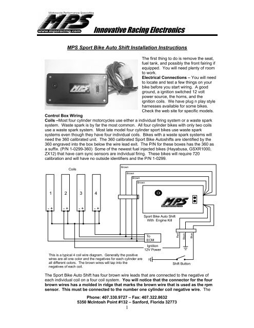
Innovative <strong>Racing</strong> Electronics<strong>MPS</strong> <strong>Sport</strong> <strong>Bike</strong> Auto Shift <strong>Installation</strong> InstructionsThe first thing to do is remove the seat,fuel tank, and possibly the front fairing ifequipped. You will need plenty of roomto work.<strong>Electric</strong>al Connections – You will needto locate and test a few things on yourbike before you start wiring. A goodground, a ignition switched 12 voltpower source, the horns, and theignition coils. We have plug n play styleharnesses available for some bikes.Check the web site for specific models.Control Box WiringCoils –Most four cylinder motorcycles use either a individual firing system or a waste sparksystem. Waste spark is by far the most common. All four cylinder bikes with only two coilsuse a waste spark system. Most late model four cylinder sport bikes use waste sparksystems even though they have four individual coils. <strong>Bike</strong>s with a waste spark systems willneed the 360 calibrated unit. The 360 calibrated <strong>Sport</strong> <strong>Bike</strong> Autoshifts are identified by the360 engraved into the box below the wire lead exit. The P/N for these boxes has the 360 asa suffix. (P/N 1-0299-360) Some of the newest fuel injected bikes (Hayabusa, GSXR1000,ZX12) that have cam sync sensors are individual firing. These bikes will require 720calibration and will have no outside identifiers and the P/N 1-0299.CoilsBrownBrownBrownBrown1 2 3 4- + - + - + - +<strong>Sport</strong> <strong>Bike</strong> Auto ShiftWith Engine KillThis is a typical 4 coil wire diagram. Generally the positivewires are all one color and the negatives for each cylinder areall different colors. The brown wires will tap into thenegatives of each coil.ToECMIgnition12V PowerRedBlackBlueShift ButtonThe <strong>Sport</strong> <strong>Bike</strong> Auto Shift has four brown wire leads that are connected to the negative ofeach individual coil on a four coil system. You will notice that the connector for the fourbrown wires has a molded in ridge that marks the brown wire that is used as the rpmsensor. This must be connected to the number one cylinder coil negative wire. ThePhone: 407.330.9727 – Fax: 407.322.86325350 McIntosh Point #132 – Sanford, Florida 327731
Innovative <strong>Racing</strong> Electronicsremaining brown wires don’t matter which coil they are connected to. On a two coil systemyou will use only two brown wires. The connector for thefour brown wires has a molded in ridge that marks thebrown wire that is used as the rpm sensor. This must beconnected to the number one and four cylinder coilnegative wire. Any of the three remaining brown wires can beused for number two and three cylinder coil. Cap off theunused brown wire ends so they don’t short. Some two coilsystems may not have enough kill time. If you experience akill time that is to short you can ground the remaining two brown wires. This will increase thekill time. You can either solder the brown wires to the coil leads (recommended) or use theprovided scotchlok splices. The <strong>Sport</strong> <strong>Bike</strong> Auto Shift will not work properly on race bikeswith Dyna Pro 4000 Ignitions and MSD Ignitions. These applications need to use the P/N 1-0238 Auto Shift With Kill.Horn Test - Unplug both your horn leads from the horn(s). Turn the key on. Using a testlight, check each horn wire for power. If one of the wires has continuous power the hornbutton circuit completes a ground circuit to operate. This is the typical Kawasaki and Suzukihorn system. A wiring diagram showing how to wire a switch to select the shifter or the hornappears below.To Red Power WireOn <strong>Sport</strong> <strong>Bike</strong> KillHornToggle SwitchConstant Power WireTo Blue Activation LeadOn <strong>Sport</strong> <strong>Bike</strong> KillCompletes A Ground WireFrom Horn ButtonIf no wires have continuous power, check them each with the horn button depressed. One ofthe two should have power with the horn button depressed. This system completes a powercircuit to operate. This is the typical Honda and Yamaha horn system. This system requiresa SPST relay to be added to the system. A wiring diagram showing how to wire a switch toselect the shifter or the horn appears below.HornToggle Switch12 Volt SPST RelayIgnition Switched12 Volt PowerTo Blue Activation LeadOn <strong>Sport</strong> <strong>Bike</strong> KillFactory Horn LeadFactory Horn LeadIf you would like to skip all the horn/relay stuff we have a nice kit to eliminate all the work ofwiring the relays. It works with either system and is a snap to wire. (P/N 1-0317 <strong>Air</strong> <strong>Shifter</strong> ToHorn Control Harness)Power, Ground, and Activation Lead – The red wire is connected to a ignition switched 12volt power source. Do not attach direct to battery! The black wire is connected to a goodground. Preferably, the battery negative post. The blue wire is the activation lead. When aground is applied to this wire the unit kills the motor for the specified time period. The hornwiring diagrams will show you how to wire it.<strong>Electric</strong> <strong>Air</strong> Valve – The <strong>Electric</strong> <strong>Air</strong> Valve has two wires. These wires are interchangeable.One needs an ignition switched 12 volt power source. The other needs a ground signal whenPhone: 407.330.9727 – Fax: 407.322.86325350 McIntosh Point #132 – Sanford, Florida 327732