Energy Harvesting Through Piezoelectric Cells for Commercial Use
Energy Harvesting Through Piezoelectric Cells for Commercial Use
Energy Harvesting Through Piezoelectric Cells for Commercial Use
- No tags were found...

Create successful ePaper yourself
Turn your PDF publications into a flip-book with our unique Google optimized e-Paper software.
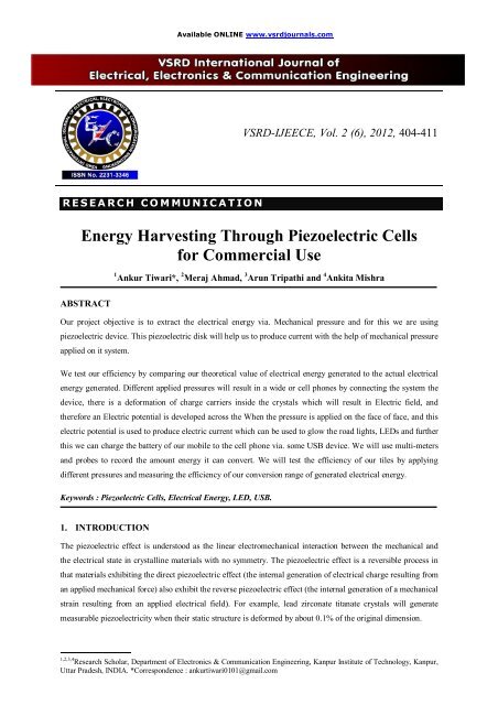
Available ONLINE www.vsrdjournals.comVSRD-IJEECE, Vol. 2 (6), 2012, 404-411R E S E A R C H C O M M U N II C A T II O N<strong>Energy</strong> <strong>Harvesting</strong> <strong>Through</strong> <strong>Piezoelectric</strong> <strong>Cells</strong><strong>for</strong> <strong>Commercial</strong> <strong>Use</strong>1 Ankur Tiwari*, 2 Meraj Ahmad, 3 Arun Tripathi and 4 Ankita MishraABSTRACTOur project objective is to extract the electrical energy via. Mechanical pressure and <strong>for</strong> this we are usingpiezoelectric device. This piezoelectric disk will help us to produce current with the help of mechanical pressureapplied on it system.We test our efficiency by comparing our theoretical value of electrical energy generated to the actual electricalenergy generated. Different applied pressures will result in a wide or cell phones by connecting the system thedevice, there is a de<strong>for</strong>mation of charge carriers inside the crystals which will result in Electric field, andthere<strong>for</strong>e an Electric potential is developed across the When the pressure is applied on the face of face, and thiselectric potential is used to produce electric current which can be used to glow the road lights, LEDs and furtherthis we can charge the battery of our mobile to the cell phone via. some USB device. We will use multi-metersand probes to record the amount energy it can convert. We will test the efficiency of our tiles by applyingdifferent pressures and measuring the efficiency of our conversion range of generated electrical energy.Keywords : <strong>Piezoelectric</strong> <strong>Cells</strong>, Electrical <strong>Energy</strong>, LED, USB.1. INTRODUCTIONThe piezoelectric effect is understood as the linear electromechanical interaction between the mechanical andthe electrical state in crystalline materials with no symmetry. The piezoelectric effect is a reversible process inthat materials exhibiting the direct piezoelectric effect (the internal generation of electrical charge resulting froman applied mechanical <strong>for</strong>ce) also exhibit the reverse piezoelectric effect (the internal generation of a mechanicalstrain resulting from an applied electrical field). For example, lead zirconate titanate crystals will generatemeasurable piezoelectricity when their static structure is de<strong>for</strong>med by about 0.1% of the original dimension.____________________________1,2,3,4 Research Scholar, Department of Electronics & Communication Engineering, Kanpur Institute of Technology, Kanpur,Uttar Pradesh, INDIA. *Correspondence : ankurtiwari0101@gmail.com
Ankur Tiwari et al / VSRD International Journal of Electrical, Electronics & Comm. Engg. Vol. 2 (6), 2012A piezoelectric disk generates a voltage when de<strong>for</strong>med (change in shape is greatly exaggerated) The Curie,however, did not predict the converse piezoelectric effect. The converse effect was mathematically deducedfrom fundamental thermodynamic principles by Gabriel Lippmann in 1881. The Curies immediately confirmedthe existence of the converse effect, and went on to obtain quantitative proof of the complete reversibility ofelectro-elasto-mechanical de<strong>for</strong>mations in piezoelectric crystals.The pyroelectric effect, where a material generates an electric potential in response to a temperature change, wasstudied by Carl Linnaeus and Franz Aepinus in the mid-18th century. Drawing on this knowledge, both RenéJust Haüy and Antoine César Becquerel posited a relationship between mechanical stress and electric charge;however, experiments by both proved inconclusive.The first demonstration of the direct piezoelectric effect was in 1880 by the brothers Pierre Curie and JacquesCurie. They combined their knowledge of pyroelectricity with their understanding of the underlying crystalstructures that gave rise to pyroelectricity to predict crystal behavior, and demonstrated the effect using crystalsof tourmaline, quartz, topaz, cane sugar, and Rochelle salt (sodium potassium tartrate tetrahydrate). Quartz andRochelle salt exhibited the most piezoelectricity2. COMPONENTS USEDPiezo electric cells.SensorsActuatorsOne aluminium metal sheet.LED,sDC converterAmplifierWires2.1. Piezo Electric <strong>Cells</strong>The piezoelectric cell is what allows us to convert the mechanical energy to electrical energy thus, utilizing ourwasted energy. The piezoelectric inputs the energy from the input signal and outputs the signal to our circuitsystem. We will buy this component as it is too physically advanced <strong>for</strong> us to construct and we do not have thetools to construct it.Page 405 of 411
Ankur Tiwari et al / VSRD International Journal of Electrical, Electronics & Comm. Engg. Vol. 2 (6), 2012Fig. 1 : Piezo Electric Cell2.2. SensorsThe principle of operation of a piezoelectric sensor is that a physical dimension, trans<strong>for</strong>med into a <strong>for</strong>ce, actson two opposing faces of the sensing element. Depending on the design of a sensor, different "modes" to loadthe piezoelectric element can be used: longitudinal, transversal and shear Detection of pressure variations in the<strong>for</strong>m of sound is the most common sensor application, e.g. piezoelectric microphones (sound waves bend thepiezoelectric material, creating a changing voltage) and piezoelectric pickups <strong>for</strong> Acoustic-electric guitars. Apiezo sensor attached to the body of an instrument is known as a microphone. <strong>Piezoelectric</strong> sensors especiallyare used with high frequency sound in ultrasonic transducers <strong>for</strong> medical imaging and also industrialnondestructive testing (NDT).Fig. 2 : <strong>Piezoelectric</strong> Disk <strong>Use</strong>d As a Guitar Pickup2.3. ActuatorsAs very high electric fields correspond to only tiny changes in the width of the crystal, this width can bechanged with better-than-µm precision, making piezo crystals the most important tool <strong>for</strong> positioning objectswith extreme accuracy — thus their use in actuators. Multilayer ceramics, using layers thinner than 100 µm,allow reaching high electric fields with voltage lower than 150 V. These ceramics are used within two kinds ofactuators: direct piezo actuators and Amplified piezoelectric actuators. While direct actuator's stroke is generallylower than 100 µm, amplified piezo actuators can reach millimeter strokes.Page 406 of 411
Ankur Tiwari et al / VSRD International Journal of Electrical, Electronics & Comm. Engg. Vol. 2 (6), 20122.4. DC ConverterOur converter, an AC/DC converter, inputs an AC source and outputs a DC source. We need a DC sourcebecause if we decide to power an energy storage device we will need to provide that with a DC source. OurAC/DC converter is built from a bridge rectifier type schematic (see schematic) since an AC/DC IC was notavailable. This block is also responsible <strong>for</strong> protecting our circuit from reverse currents, through the use ofdiodes. This block receives its signal from the piezoelectric. However, there is a lot of communication withinthe block as this is where the real circuitry that runs our system is built. It is at this block that we no longer havemechanical energy, but electrical energy, which is output to whatever our output may be, whether an LED signor energy storage device.2.5. Amplifier/StorageHere we amplify the current since we are expecting it to be very small. . Since we have a capacitor bank thisdissipation will last longer than if we simply had a direct connection to our converter and amplifier. Thus, ourLEDs, or whatever our output source is, will have power supplied <strong>for</strong> a long period of time. We can also test theefficiency of our energy storage by simply monitoring the time that the output device runs <strong>for</strong> to see whether ornot our storage elements actually behaves the way we expect it to and prolongs the “ON” period of our LEDslonger than if the LEDs, or other output Storing and amplifying our energy can be achieved with a circuit thatcontains capacitors and an op-amp. We may also use a few super capacitors; however we feel that the bestapproach will be a capacitor bank. We will need to test the components to find out which chips are suitable withour circuit since we need capacitors that are properly rated <strong>for</strong> our system requirements. We will test this bymeasuring our power usage with PSPICE simulations as well as direct measurements from our piezoelectricrods to see the voltage produced. Combining this in<strong>for</strong>mation we will have an exact idea of what value ofcapacitors we will need to use in our capacitor bank. Our capacitor bank will be a certain number of capacitorsconnected in parallel. Each capacitor will take in a small amount of current at a time, this is distributed amongstthe capacitors fairly evenly, although not exact since no capacitor has the exact same value. Then our outputdevice, the LEDs will be powered by the current dissipating from our capacitors device, was connected straightto our converter and amplifier. Our amplifier is very simple. Its purpose is to amplify the current, thus alsoreducing the voltage, so that we have more power at our output since we need a higher current to drive anydevice than the current we get directly from the piezoelectric rods. We can test our energy device as mentionedabove and we can test our amplifier through simulating it in PSPICE to see what the best resistor combinationwould be to give us the right current <strong>for</strong> our output.3. WORKINGA piezoelectric disk generates a voltage when de<strong>for</strong>med .It means that when the pressure is applied on the faceof the device , there is a de<strong>for</strong>mation of charge carriers inside the crystals which will result in Electric field, andthere<strong>for</strong>e an Electric potential is developed across the face, and this electric potential is used to produce electriccurrent which is used to glow the lights, LED,s, and further this we can charge the battery of our mobile orcellphones by connecting the device to the cellphone via. some USB device.The diagram showing that as the pressure is applied to the faces there is a generation of electric current which isPage 407 of 411
Ankur Tiwari et al / VSRD International Journal of Electrical, Electronics & Comm. Engg. Vol. 2 (6), 2012indicated by the Galvanometer..Fig. 3 : Pressure Is Applied To the Faces There Is a Generation of Electric CurrentWhich Is Indicated By the GalvanometerThe piezoelectric effect occurs when the charge balance within a material’s crystal lattice is disturbed. Whenthere is no applied stress on the material, the positive and negative charges are evenly distributed so there is nopotential difference. When the lattice is changed slightly, the charge imbalance creates a potential difference,often as high as several thousand volts. However, the current is extremely small and only causes a small electricshock. The converse piezoelectric effect occurs when the electrostatic field that an electrical current createscauses the atoms in the material to move slightlyA vibrating piezoelectric element can be considered as sinusoidal current source at a particular time (t), i p (t) inparallel with its internal electrode capacitance C p . The magnitude of the polarization current I p varies withmechanical excitation level of the piezoelectric element. These wave<strong>for</strong>ms can be divided into two intervals. Ininterval 1, denoted as u, the polarization current is charging the electrode capacitance of the piezoelectricelement. During this time all diodes are reverse biased and no current flows to the output.At the end of the commutation interval, interval 2 begins, and output current flows to the capacitor C rect and theload. By assuming C rect >> C P , the majority of the current will be delivered as output current. The peak outputpower occurs when V rect I P /2 U C P or one half the peak open circuit voltage of the piezoelectric element. Themagnitude of the polarization current I P generated by the piezoelectric transducer, and hence the optimalrectifier voltage, may not be constant as it depends upon the vibration level exciting the piezoelectric element.This creates the need <strong>for</strong> flexibility in the circuit. i.e., the ability to adjust the output voltage of the rectifier toachieve maximum power transferPage 408 of 411
Ankur Tiwari et al / VSRD International Journal of Electrical, Electronics & Comm. Engg. Vol. 2 (6), 20124. BENEFITS OF THIS PROJECTGenerate energy without the need of the elements (Solar, Hydro, Wind, etc.)Utilize otherwise wasted energy thus, is more efficient use of our energy.Ability to reduce dependence on energy grid and generate the energy that one requires by themselves.Increased sustainabilityPotential to be utilized everywhere from buildings, sidewalks, and roadsProvides a mean of energy generation to communities isolated from power infrastructure, such as thirdworld countries and islands.5. PRODUCT FEATURESMechanical to Electrical energy conversionSelf contained systemLong lifespan of piezoelectric deviceAbility to adjust features to manipulate energy generation<strong>Energy</strong> storage or use feature6. FUTURE SCOPESeries <strong>Piezoelectric</strong> materials embedded on road to glow the road lights as shown :Page 409 of 411
Ankur Tiwari et al / VSRD International Journal of Electrical, Electronics & Comm. Engg. Vol. 2 (6), 2012In this figure we see the piezoelectric cells are embedded on the whole road and these embedded piezoelectriccells are connected with external charge storing device with the help of connectors, and the charge so developedare then supplied to all the street lights as shown in the figure.Economically competitive with the traditional carbon-based energy production.The electrical storage system, which is integrated in the roads, rail roads, and runways, does not take up anynew public space and functions in all weather conditions.Once embedded into road ways or railways, generators require minimal maintenance.These solutions can also serve as in<strong>for</strong>mation gatherers in future “smart roads” measuring a truck or railcar’s weight in real time, send data back through a self-powered’ wireless connection. These could be usedin weighing stations.7. CONCLUSIONWhen the pressure is applied on the face of the device, there is a de<strong>for</strong>mation of charge carriers inside thecrystals which will result in Electric field, and there<strong>for</strong>e an Electric potential is developed across the face, andthis electric potential is used to produce electric current which is used to glow the lights, LED,s, and further thiswe can charge the battery of our mobile or cell phones by connecting the device to the cell phone via. someUSB device.8. ACKOWLEDGMENTThe authors of this technical Paper would like to express their sincere thanks to VSRD International Journal <strong>for</strong>providing us excellent guidance, encouragement and inspiration through-out the project work. The authors wishPage 410 of 411
Ankur Tiwari et al / VSRD International Journal of Electrical, Electronics & Comm. Engg. Vol. 2 (6), 2012to thank all individuals who contributed directly or indirectly in completing this project work.9. REFERENCES[1] <strong>Energy</strong> Harvester Produces Power from Local Environment, Eliminating Batteries in Wireless Sensors[2] Knee-Mounted Device Generates Electricity While You Walk, By Chad Skelton, 7 Feb 2008[3] <strong>Piezoelectric</strong> <strong>Energy</strong> <strong>Harvesting</strong> Research at NTU[4] Some <strong>Energy</strong> <strong>Harvesting</strong> Research @NUS[5] Noise in Physical Systems Laboratory[6] Enhants project at Columbia University[7] Architectures <strong>for</strong> Vibration-Driven Micropower Generators, P. D. Mitcheson, T. C. Green, E. M. Yeatman,A. S. Holmes"[8] <strong>Energy</strong> Harvester Produces Power from Local Environment, Eliminating Batteries in Wireless Sensors.Page 411 of 411