

zer WL - RoboticsConnection
zer WL - RoboticsConnection
zer WL - RoboticsConnection

You also want an ePaper? Increase the reach of your titles
YUMPU automatically turns print PDFs into web optimized ePapers that Google loves.
RS-232<br />
Serializ S <strong>zer</strong> <strong>WL</strong><br />
v2.1 User GGuide<br />
Summ merour Roboticcs<br />
Corporation, , www.roboticssconnection.com,<br />
2004-2008.<br />
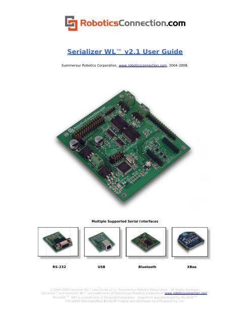
MMultiple<br />
Supported<br />
Serial IInterfaces<br />
USB<br />
BBluetooth<br />
XBee<br />
©2004-2008 Seriali<strong>zer</strong> S <strong>WL</strong> UUser<br />
Guide v2.1 - Summerour Roobotics<br />
Corporation.<br />
All Rights RReserved.<br />
Seriali<strong>zer</strong><br />
and Ser riali<strong>zer</strong> <strong>WL</strong> are trademarks of Summerour<br />
Robottics<br />
Corporation (www.roboticscoonnection.com)<br />
Microsoft .NET is a trademmark<br />
of Microsoft Corporation. Hyyperterm<br />
was deeveloped<br />
by Microo<br />
soft<br />
The e eb100 EmbeddeedBlue<br />
Bluetoothh<br />
module was devveloped<br />
by A7Enngineering,<br />
Inc.
Table of Contents<br />
Seriali<strong>zer</strong> <strong>WL</strong> User Guide v2.1<br />
Table of Contents .......................................................................................................................................................................................... 2<br />
Overview ....................................................................................................................................................................................................... 3<br />
Seriali<strong>zer</strong> <strong>WL</strong> Pinout: ................................................................................................................................................................................ 9<br />
Applying Power: ......................................................................................................................................................................................... 10<br />
Configuring the onboard H-Bridges: .......................................................................................................................................................... 10<br />
Serial<br />
Hardware Configuration: .................................................................................................................................................................. 12<br />
RS-232 Serial Interface Module: .......................................................................................................................................................... 12<br />
TLL Voltage Levels: ............................................................................................................................................................................. 14<br />
General Purpose, Analog, and I2C I/O lines: ............................................................................................................................................. 16<br />
Servo Power Select Jumper: ....................................................................................................................................................................... 17<br />
Protocol<br />
Details ........................................................................................................................................................................................... 18<br />
Booting Up: ........................................................................................................................................................................................... 18<br />
Serial Software Configuration: ............................................................................................................................................................. 19<br />
Command<br />
Set Summary ............................................................................................................................................................................. 21<br />
fw ........................................................................................................................................................................................................... 21<br />
reset ....................................................................................................................................................................................................... 21<br />
blink ....................................................................................................................................................................................................... 21<br />
cmps03 .................................................................................................................................................................................................. 22<br />
cfg enc ................................................................................................................................................................................................... 22<br />
cfg baud ................................................................................................................................................................................................. 22<br />
cfg units ................................................................................................................................................................................................. 23<br />
getenc .................................................................................................................................................................................................... 23<br />
clrenc ..................................................................................................................................................................................................... 24<br />
setio ....................................................................................................................................................................................................... 24<br />
getio ....................................................................................................................................................................................................... 24<br />
maxez1 .................................................................................................................................................................................................. 25<br />
mogo ...................................................................................................................................................................................................... 25<br />
vpid ........................................................................................................................................................................................................ 26<br />
digo ........................................................................................................................................................................................................ 26<br />
dpid ........................................................................................................................................................................................................ 27<br />
pids ........................................................................................................................................................................................................ 28<br />
pwm ....................................................................................................................................................................................................... 28<br />
step ........................................................................................................................................................................................................ 30<br />
sweep ..................................................................................................................................................................................................... 30<br />
stop ........................................................................................................................................................................................................ 31<br />
sensor ..................................................................................................................................................................................................... 31<br />
servo ...................................................................................................................................................................................................... 32<br />
sp03 ....................................................................................................................................................................................................... 32<br />
srf04 ....................................................................................................................................................................................................... 33<br />
srf05 ....................................................................................................................................................................................................... 33<br />
pping ...................................................................................................................................................................................................... 33<br />
srf08 ....................................................................................................................................................................................................... 34<br />
srf10 ....................................................................................................................................................................................................... 34<br />
tpa81 ...................................................................................................................................................................................................... 34<br />
vel .......................................................................................................................................................................................................... 34<br />
restore .................................................................................................................................................................................................... 34<br />
Line[7] ................................................................................................................................................................................................... 35<br />
i2cp currAddr newAddr ........................................................................................................................................................................ 35<br />
i2c [data] ........................................................................................................................................................................ 36<br />
Upgrading the Firmware: ............................................................................................................................................................................ 38<br />
Warranty & Disclaimer Information: ......................................................................................................................................................... 40<br />
Seriali<strong>zer</strong> Libraries & Documentation: ....................................................................................................................................................... 40<br />
PID Configuration Examples: ..................................................................................................................................................................... 41<br />
Velocity PID (VPID) .................................................................................................................................................................................. 41<br />
Distance PID (DPID) .................................................................................................................................................................................. 42<br />
Seriali<strong>zer</strong> Dimensions: ............................................................................................................................................................................ 43<br />
Seriali<strong>zer</strong> Maximum Ratings .................................................................................................................................................................. 43<br />
ASCII Character Set .................................................................................................................................................................................... 44<br />
Contact<br />
Information: ................................................................................................................................................................................... 45<br />
©2004-2008 Seriali<strong>zer</strong> User Guide v2.1 - Summerour Robotics Corporation. All Rights Reserved. 2<br />
Seriali<strong>zer</strong> and Seriali<strong>zer</strong> <strong>WL</strong> are trademarks of Summerour Robotics Corporation (www.roboticsconnection.com)<br />
Microsoft .NET is a trademark of Microsoft Corporation. Hyperterm was developed by Microsoft<br />
The eb505 EmbeddedBlue Bluetooth module was developed by A7Engineering, Inc.<br />
Page:
Overvview<br />
Seconnd<br />
Generation n Seriali<strong>zer</strong>:<br />
Seriaali<strong>zer</strong><br />
<strong>WL</strong>L<br />
User GGuide<br />
v2. .1<br />
Figure 1 – Original<br />
Seriali<strong>zer</strong><br />
with a subseet<br />
of all of the various compoonents<br />
interfacced<br />
to it.<br />
The Seeriali<strong>zer</strong><br />
<strong>WL</strong> is i the second ggeneration<br />
of the<br />
Seriali<strong>zer</strong>. It has been uppdated<br />
to provide<br />
customers<br />
with a selection of se erial interfacess,<br />
which now innclude<br />
RS-232, , USB, Bluetooth,<br />
and XBee. Since two of<br />
the serial<br />
interfaces are now wireleess,<br />
we decidedd<br />
append ‘<strong>WL</strong>’ to the end of tthe<br />
name to diifferentiate<br />
thee<br />
new board<br />
from the original one. TThe<br />
‘<strong>WL</strong>’ basicaally<br />
stands for ‘ ‘Wireless’.<br />
Each sserial<br />
interface quickly plugs into the two siingle<br />
row headders<br />
(where thee<br />
old DB-9 connector<br />
used too<br />
be), and<br />
communica ation w/ the booard<br />
can be esttablished<br />
in lesss<br />
than a minutte.<br />
Only one serial interfacee<br />
can bee<br />
used at a tim me with the Serriali<strong>zer</strong><br />
<strong>WL</strong>.<br />
The seerial<br />
protocol used<br />
between tthe<br />
original Serriali<strong>zer</strong>,<br />
and tthe<br />
Seriali<strong>zer</strong> W<strong>WL</strong>,<br />
are identical.<br />
Hence<br />
the firmware<br />
is ident tical between tthe<br />
two modelss<br />
as well.<br />
Easy RRobot<br />
Contro ol using .NET:<br />
The Seeriali<strong>zer</strong><br />
<strong>WL</strong> board b providess<br />
a ready-to-usse<br />
solution to interface<br />
Microsoft<br />
.NET applications,<br />
Microssoft<br />
Robotics Studio Servicees<br />
(MSRS), andd<br />
C++ applicattions<br />
to common<br />
robotic harddware.<br />
Never<br />
©2004-2008 Seriali<strong>zer</strong> S<br />
User Guide v2.1 - Summmerour<br />
Roboticcs<br />
Corporation. All Rights Reserrved.<br />
Seriali<strong>zer</strong><br />
and Ser riali<strong>zer</strong> <strong>WL</strong> are trademarks of Summerour<br />
Robottics<br />
Corporation (www.roboticscoonnection.com)<br />
Microsoft .NET is a trademmark<br />
of Microsoft Corporation. Hyyperterm<br />
was deeveloped<br />
by Microosoft<br />
The e eb505 EmbeddeedBlue<br />
Bluetoothh<br />
module was devveloped<br />
by A7Enngineering,<br />
Inc.<br />
Pagee:<br />
3
Seriali<strong>zer</strong> <strong>WL</strong> User Guide v2.1<br />
before has it been this easy to interface DC motors, servos, analog sensors, I2C devices, single and<br />
quadrature encoders, switches/relays, and other devices. Although the Seriali<strong>zer</strong> was developed for<br />
computers running Windows Vista, XP, XP Embedded, or WinCE and the Microsoft .NET Framework, it can<br />
also communicate with any controller which contains a free serial port.<br />
Develop Smarter Applications:<br />
We wanted to enable .NET developers and Robotics Studio developers interested in developing robotic<br />
applications to hit the ground running. Why waste time re-implementing bit-twiddling routines when that<br />
time could be better spent developing a higher level (and smarter) application that allows your robot to do<br />
something meaningful? With the exception of configuring a few parameters, there's no low level<br />
programming involved. The Seriali<strong>zer</strong> <strong>WL</strong> links both the .NET framework, and Robotics Studio, with low<br />
level robotic hardware using a simple serial port.<br />
Free .NET library with Full Documentation:<br />
Our freely available .NET Seriali<strong>zer</strong> library assembly allows customers to quickly develop applications<br />
which can instantly communicate with the Seriali<strong>zer</strong>. Once an application links in the<br />
Seriali<strong>zer</strong>Lib.dll, the entire Seriali<strong>zer</strong> interface will be available.<br />
We also offer a C# GUI application example, which contains a user control to invoke every method in the<br />
Seriali<strong>zer</strong>Lib.dll assembly. Developers can use it to test out their Seriali<strong>zer</strong>, or as a source for examples<br />
for their own application. The How-To document provides the exact steps for adding the library to your<br />
application.<br />
We realize that it's important that developers have easy and quick access to the Seriali<strong>zer</strong> Library<br />
interface. Therefore, we provide excellent MSDN style web pages to document the entire interface, as<br />
well as provide links to the supported sensors and components.<br />
Free Seriali<strong>zer</strong> Services for Microsoft Robotics Studio (MSRS):<br />
We also provide our Seriali<strong>zer</strong> Services for free, which allow customers to quickly leverage the features of<br />
the Seriali<strong>zer</strong> using Microsoft Robotics Studio Services. The Seriali<strong>zer</strong> Services include our Traxster<br />
Drive Service, which serves not only as a functional service that allows customers to immediately control<br />
one of our Traxster Robot Kits (using a Seriali<strong>zer</strong>/Seriali<strong>zer</strong> <strong>WL</strong>), but it also serves as an example for<br />
interfacing the various Seriali<strong>zer</strong> Services.<br />
Free Seriali<strong>zer</strong> C++ Library:<br />
James Y. Wilson (http://www.learningce.com) has graciously written a Seriali<strong>zer</strong> C++ library, which<br />
closely follows the same interface as our .NET library. The C++ Library also includes a very useful<br />
Testing Harness to help you understand how to use the library. Please see the License.txt file before<br />
using.<br />
©2004-2008 Seriali<strong>zer</strong> User Guide v2.1 - Summerour Robotics Corporation. All Rights Reserved. 4<br />
Seriali<strong>zer</strong> and Seriali<strong>zer</strong> <strong>WL</strong> are trademarks of Summerour Robotics Corporation (www.roboticsconnection.com)<br />
Microsoft .NET is a trademark of Microsoft Corporation. Hyperterm was developed by Microsoft<br />
The eb505 EmbeddedBlue Bluetooth module was developed by A7Engineering, Inc.<br />
Page:
All you need is a serial port:<br />
Seriali<strong>zer</strong> <strong>WL</strong> User Guide v2.1<br />
Using our simple serial control protocol, the Seriali<strong>zer</strong> can be controlled by any device featuring a serial<br />
port. This could be a Personal Computer, a PDA, a PC104 board, a Single Board Computer, or a<br />
microcontroller. To make developing applications with .NET and Robotics Studio faster, we provide both a<br />
Seriali<strong>zer</strong> assembly library, as well as Seriali<strong>zer</strong> Services, which implements the protocol, and provides<br />
an easy to use interface. All the customer has to do is invoke the interface to make the magic happen.<br />
Serial Protocol:<br />
The Seriali<strong>zer</strong> Protocol is a simple set of rules defined to allow a program running on a host computer to<br />
communicate with a Seriali<strong>zer</strong> board over a serial connection. The protocol commands are made up of<br />
8-bit ASCII characters for ease of use and to reduce bandwidth usage. The use of ASCII characters also<br />
allows users to send/receive commands to/from the Seriali<strong>zer</strong> via a simple Hyperterm program, or a<br />
dedicated application running on another computer for debugging purposes.<br />
Upgradeable Firmware:<br />
New sensors and components, appropriate for use in robotics, are introduced to the market daily.<br />
We realized that the ability to add support for these new sensors and components would make the<br />
Seriali<strong>zer</strong> <strong>WL</strong> even more useful. Therefore, we provided a firmware upgrading facility within the<br />
Seriali<strong>zer</strong> <strong>WL</strong>. Not only can the firmware be upgraded, but it is as easy as 1-2-3.<br />
Upgrading the firmware is as easy as 1.) Download the latest firmware from our site, 2.) Upload the<br />
firmware to the Seriali<strong>zer</strong> <strong>WL</strong> with the help of Hyperterm, and 3.) Cycling power.<br />
We are also open to requests to add new sensors and components to the current lineup. Customers can<br />
send requests to techsupport@roboticsconnection.com for consideration. If we believe the request is<br />
appropriate, we will add support to the firmware, if possible. Since the Seriali<strong>zer</strong>’s initial launch, we have<br />
added the following functionality to the Seriali<strong>zer</strong> per customer requests:<br />
• Velocity and Distance PID Control and State<br />
• Setting multiple GPIOs simultaneously<br />
• Pre/Post (.NET) events before/after establishing serial communications w/ the Seriali<strong>zer</strong><br />
• Bipolar Stepper motor control (step and sweep)<br />
• Maxbotix MaxSonar-EZ1 Sonar interface<br />
• Generic I2C interface<br />
• Pwm Ramping<br />
• Factory Restore interface<br />
• Reset interface<br />
• Line Following Sensor interface<br />
• Add four extra servo ports for a total of six available servo ports<br />
©2004-2008 Seriali<strong>zer</strong> User Guide v2.1 - Summerour Robotics Corporation. All Rights Reserved. 5<br />
Seriali<strong>zer</strong> and Seriali<strong>zer</strong> <strong>WL</strong> are trademarks of Summerour Robotics Corporation (www.roboticsconnection.com)<br />
Microsoft .NET is a trademark of Microsoft Corporation. Hyperterm was developed by Microsoft<br />
The eb505 EmbeddedBlue Bluetooth module was developed by A7Engineering, Inc.<br />
Page:
Seriali<strong>zer</strong> <strong>WL</strong> User Guide v2.1<br />
Supports the most popular robotic sensors and components:<br />
The Seriali<strong>zer</strong> provides an interface to query and control some of the most popular robotic components<br />
on the market. The current list includes:<br />
I2C Devices:<br />
• Any I2C device (using generic I2C interface)<br />
• <strong>RoboticsConnection</strong> Line Following Sensor<br />
• Devantech SRF02<br />
• Devantech SRF04<br />
• Devantech SRF05<br />
• Devantech SRF08<br />
• Devantech SRF10<br />
• Devantech TPA81 Thermopile<br />
• Devantech SP03 Speech Synthesi<strong>zer</strong><br />
• Devantech CMPS03 Electronic Compass<br />
• Devantech LCD03<br />
Analog Sensors (5 Sensor Inputs):<br />
• <strong>RoboticsConnection</strong> Ambient Temperature Sensor Board<br />
• <strong>RoboticsConnection</strong> Potentiometer Sensor Board<br />
• Sharp GP2D12 infrared distance sensor<br />
• Sharp GP2D120 infrared distance sensor<br />
• Onboard battery voltage level monitor– analog input 5<br />
Digital I/O Lines (10 I/O Lines + 4 Encoder Input lines):<br />
• <strong>RoboticsConnection</strong> Pushbutton I/O Board<br />
• Parallax PING))) Sonar<br />
• Maxbotix MaxSonar-EZ1 Sonar<br />
• Single and Quadrature Encoder inputs<br />
• NOTE: Six I/O lines are used for Servo control (4,5,6,7,8, & 9) and two are used for I2C<br />
communications (1,2). Thus if you’re using Servos or I2C devices, on any of these pins, you<br />
won’t be able to use them for any other I/O.<br />
Motors:<br />
LEDs:<br />
• Two DC drive motors up to 4A each<br />
• One Bipolar Stepper Motor<br />
• Six Standard or Digital Hobby Servos<br />
• Gamoto External PID Controller (uses generic I2C interface)<br />
• External H-Bridge control<br />
• Built in Velocity and Distance PID Motor Control Algorithms<br />
• One Red Power LED<br />
• Two Green LEDs are used as a programmable heartbeat<br />
• Two Bi-Color (Green/Red) are used to display the PWM duty cycle percentage (0-100) and<br />
direction of current through each motor (and thus motor direction).<br />
©2004-2008 Seriali<strong>zer</strong> User Guide v2.1 - Summerour Robotics Corporation. All Rights Reserved. 6<br />
Seriali<strong>zer</strong> and Seriali<strong>zer</strong> <strong>WL</strong> are trademarks of Summerour Robotics Corporation (www.roboticsconnection.com)<br />
Microsoft .NET is a trademark of Microsoft Corporation. Hyperterm was developed by Microsoft<br />
The eb505 EmbeddedBlue Bluetooth module was developed by A7Engineering, Inc.<br />
Page:
No neeed<br />
for serial logic level coonversion:<br />
Seriaali<strong>zer</strong><br />
<strong>WL</strong>L<br />
User GGuide<br />
v2. .1<br />
The Seeriali<strong>zer</strong><br />
<strong>WL</strong> can c be interfacced<br />
using any oof<br />
the followingg<br />
serial interfaces<br />
modules:<br />
•<br />
•<br />
•<br />
•<br />
•<br />
RS-232<br />
USB<br />
Bluetooth<br />
XBee<br />
TTL (header<br />
located on Seeriali<strong>zer</strong><br />
<strong>WL</strong>, not on modulees)<br />
RS-232<br />
If you want to comm municate with tthe<br />
Seriali<strong>zer</strong> W<strong>WL</strong><br />
from yourr<br />
PC, simply plug<br />
in one of thhe<br />
serial<br />
interfaace<br />
modules mentioned m abovve<br />
into the Seriiali<strong>zer</strong><br />
<strong>WL</strong>. WWhile<br />
only one module will woork<br />
with the<br />
Serialii<strong>zer</strong><br />
<strong>WL</strong> at a time, you can swap the modules<br />
out as needed.<br />
If you hhave<br />
a microcoontroller<br />
or<br />
embeddded<br />
device wh hich needs to ttalk<br />
serially at TTL voltage levvels,<br />
simply usse<br />
the 0.100" hheader<br />
on the<br />
Serialii<strong>zer</strong><br />
<strong>WL</strong> base board, and reemove<br />
one jummper.<br />
Flexibble<br />
H-Bridge Control: C<br />
Figure<br />
2: Multiplle<br />
Supported Wired and WWireless<br />
Serial<br />
Interfaces<br />
USB<br />
BBluetooth<br />
Not onnly<br />
can you use e the onboard h-bridges to drive<br />
two DC motors<br />
(up to 4AA<br />
each), but yoou<br />
can also<br />
drive eexternal<br />
h-brid dges (with a higgher<br />
or lower ccapacity)<br />
with the change of a jumper. If tthat's<br />
not<br />
enough,<br />
you can driv ve the onboardd<br />
h-bridges froom<br />
an external controller.<br />
This flexibility<br />
allows s the customerr<br />
to use the Seriali<strong>zer</strong><br />
in maany<br />
applicationns.<br />
XBee<br />
Using the Generic I2 2C command, yyou<br />
can ALSO eeasily<br />
interfacee<br />
up to 8 Gamooto<br />
PID Motor Driver boards, ,<br />
withouut<br />
tying up the onboard h-briidges.<br />
This allows<br />
you to usse<br />
the onboard h-bridges to ccontrol<br />
two<br />
motors<br />
(or a bipolar stepper motorr),<br />
and use thee<br />
Gamoto PID DDrivers<br />
to conttrol<br />
extra motoors.<br />
Figuure<br />
3: Gamoto PID Motor Conntroller<br />
Board<br />
©2004-2008 Seriali<strong>zer</strong> S<br />
User Guide v2.1 - Summmerour<br />
Roboticcs<br />
Corporation. All Rights Reserrved.<br />
7<br />
Seriali<strong>zer</strong><br />
and Ser riali<strong>zer</strong> <strong>WL</strong> are trademarks of Summerour<br />
Robottics<br />
Corporation (www.roboticscoonnection.com)<br />
Microsoft .NET is a trademmark<br />
of Microsoft Corporation. Hyyperterm<br />
was deeveloped<br />
by Microosoft<br />
The e eb505 EmbeddeedBlue<br />
Bluetoothh<br />
module was devveloped<br />
by A7Enngineering,<br />
Inc.<br />
Pagee:
Seriali<strong>zer</strong> <strong>WL</strong> User Guide v2.1<br />
Single and Quadrature Wheel Encoder and PID Control Algorithm support included:<br />
Since it's important to know where your robot has been, where it is now, and where it's going, we also<br />
added the capability to query two single or two quadrature encoders with fully configurable PID control.<br />
You can guarantee that your robot travels the exact distance you command it, at the specified speed.<br />
Each Proportional, Integral, Derivative, and Loop parameter can be configured for your personal drive<br />
train (with some exceptions). Robot velocity, distance, and direction can be extracted from the encoded<br />
inputs. The current PID state can also be queried, so you can determine when the latest PID distance<br />
command has finished. Please see the PID configuration section at the end of this document for<br />
information regarding PID configuration.<br />
©2004-2008 Seriali<strong>zer</strong> User Guide v2.1 - Summerour Robotics Corporation. All Rights Reserved. 8<br />
Seriali<strong>zer</strong> and Seriali<strong>zer</strong> <strong>WL</strong> are trademarks of Summerour Robotics Corporation (www.roboticsconnection.com)<br />
Microsoft .NET is a trademark of Microsoft Corporation. Hyperterm was developed by Microsoft<br />
The eb505 EmbeddedBlue Bluetooth module was developed by A7Engineering, Inc.<br />
Page:
Seriali<strong>zer</strong> <strong>WL</strong> Pinout:<br />
Seriali<strong>zer</strong> <strong>WL</strong> User Guide v2.1<br />
Figure 4: Seriali<strong>zer</strong> <strong>WL</strong> Pinout<br />
Before you can interface any components to the Seriali<strong>zer</strong> <strong>WL</strong>, you need to know how they interface.<br />
The picture above shows all of the I/O lines and Connectors on the Seriali<strong>zer</strong>, which includes:<br />
• One Power Input Terminal (0-12V)<br />
• One Serial Interface Module Header (please note location of Pin1)<br />
• One TTL Serial I/O Communication Port<br />
• Two Encoder Ports – Single and Dual Quadrature Channels supported<br />
• Two DC Motor Terminals – Handles motor current draw up to 4A, each terminal<br />
• One I2C Port – SDA, SCL, 5V, Gnd – These lines tie up I/O pins 1 and 2 when used.<br />
• One Analog Port with six analog inputs – one input is tied internally to the supply voltage<br />
• One General Purpose I/O Port with 10 I/O lines – 4,5,6,7,8, & 9 can be used to control six servos<br />
• One Reset Button<br />
• Jumper bank to configure H-Bridges and Serial I/O communication<br />
• Servo power regulator jumper<br />
• Two Green User programmable LEDs, and one Red Power LED<br />
• One Green & one Red LED per DC Motor Port to show current flow direction through motors<br />
©2004-2008 Seriali<strong>zer</strong> User Guide v2.1 - Summerour Robotics Corporation. All Rights Reserved.<br />
Seriali<strong>zer</strong> and Seriali<strong>zer</strong> <strong>WL</strong> are trademarks of Summerour Robotics Corporation (www.roboticsconnection.com)<br />
Microsoft .NET is a trademark of Microsoft Corporation. Hyperterm was developed by Microsoft<br />
The eb505 EmbeddedBlue Bluetooth module was developed by A7Engineering, Inc.<br />
Page:<br />
9
Seriaali<strong>zer</strong><br />
<strong>WL</strong>L<br />
User GGuide<br />
v2. .1<br />
Applyying<br />
Power: :<br />
This iss<br />
one of the mo ost important ssteps<br />
in gettingg<br />
the Seriali<strong>zer</strong>r<br />
<strong>WL</strong> up and communicating<br />
with your<br />
host controller.<br />
You MUST make ssure<br />
that you apply<br />
power to the Power Terrminal<br />
using the<br />
correct<br />
polaritty.<br />
Reverse Po olarity will dammage<br />
the Seriali<strong>zer</strong><br />
<strong>WL</strong>. Wee<br />
are not respoonsible<br />
for suchh<br />
damage, nor r<br />
do we warranty agai inst such damaage.<br />
Make sure<br />
you take timme<br />
to apply powwer<br />
correctly. Otherwise, it<br />
could get costly.<br />
To powwer<br />
the Serializ <strong>zer</strong> <strong>WL</strong>, simplyy<br />
connect the gground<br />
wire froom<br />
your supplyy<br />
to the screw terminal<br />
labeledd<br />
“Gnd”, and then<br />
connect thhe<br />
positive wiree<br />
from your suupply<br />
to the scrrew<br />
terminal laabeled<br />
“+”.<br />
NOTEE:<br />
Maximum sup pply voltage caannot<br />
exceed 112V<br />
DC.<br />
Figure 5 – PPower<br />
Supply TTerminal<br />
Once ppower<br />
is supplied,<br />
you shouldd<br />
see the Red Power LED lighht<br />
up, and the two User definnable<br />
Green<br />
LEDs sshould<br />
be twiddling<br />
back andd<br />
forth. Also mmake<br />
sure you have a power ssupply<br />
which ccan<br />
supply at<br />
least 1 amp of power<br />
out or more, especially if you<br />
have many components cconnected<br />
(e.g.<br />
sensors, etc. ).<br />
In factt,<br />
if you have components c<br />
atttached,<br />
we sugggest<br />
you use a power supply<br />
rated at 1.5AA<br />
to 2A.<br />
Confiiguring<br />
the onboard H- Bridges:<br />
Not onnly<br />
can you use e the onboard h-bridges to drive<br />
two DC motors<br />
(up to 4AA<br />
each), but yoou<br />
can also<br />
drive eexternal<br />
h-brid dges (with a higgher<br />
or lower ccapacity)<br />
with the change of a jumper. If tthat's<br />
not<br />
enough,<br />
you can driv ve the onboardd<br />
h-bridges froom<br />
an external controller.<br />
There are four jumpe ers used to connfigure<br />
the H-BBridges<br />
(picturred<br />
below). Noote:<br />
The leftmoost<br />
jumper is<br />
used ffor<br />
Serial Comm munication connfiguration,<br />
andd<br />
doesn’t affecct<br />
h-bridge opeeration.<br />
If you want to drive<br />
externnal<br />
h-bridges, the t traces betwween<br />
the pins ccan<br />
be cut, andd<br />
the h-bridgess<br />
can be conneected<br />
via<br />
jumpeer<br />
wires to the pins at this heeader.<br />
(v1.0 booards<br />
came with<br />
jumpers, whhich<br />
also need to be removedd<br />
if driviing<br />
external h-bridges)<br />
If yoou<br />
decide to goo<br />
back to using the onboard hh-bridges,<br />
you can add<br />
jumpeers<br />
back at that t time, to restoore<br />
it to factoryy<br />
operation.<br />
Figure 6 – H-Bridge Jummpers<br />
©2004-2008 Seriali<strong>zer</strong> S<br />
User Guide v2.1 - Summmerour<br />
Roboticcs<br />
Corporation. All Rights Reserrved.<br />
Seriali<strong>zer</strong><br />
and Ser riali<strong>zer</strong> <strong>WL</strong> are trademarks of Summerour<br />
Robottics<br />
Corporation (www.roboticscoonnection.com)<br />
Microsoft .NET is a trademmark<br />
of Microsoft Corporation. Hyyperterm<br />
was deeveloped<br />
by Micro<br />
The e eb505 EmbeddeedBlue<br />
Bluetoothh<br />
module was devveloped<br />
by A7Enngineering,<br />
Inc.<br />
10<br />
osoft<br />
Page:
Seriaali<strong>zer</strong><br />
<strong>WL</strong>L<br />
User GGuide<br />
v2. .1<br />
The internal<br />
H-Bridges<br />
(rated at 4AA<br />
each) are connfigured<br />
to be driven by the onboard controller<br />
from the<br />
factoryy.<br />
In this conf figuration the ttraces<br />
on the bbottom<br />
of the bboard<br />
connect tthe<br />
pins so Jummpers<br />
are not<br />
needed.<br />
If you wish to surpas ss the internal H-Bridges, and<br />
drive externaal<br />
H-Bridges ww/<br />
a higher rating,<br />
you can cuut<br />
the traaces<br />
on the bottom<br />
of the booard,<br />
and conneect<br />
the h-bridgges<br />
to the pins w/ jumper wirres<br />
as shown<br />
(in oraange)<br />
below:<br />
If you cut the traces and then decide<br />
to go back to using the onboard<br />
H-bridgges,<br />
simply make sure all<br />
jumpeers<br />
are installed d across the fivve<br />
H-Bridge pinns<br />
(as shown aabove).<br />
Figure<br />
7 – H-Bridge<br />
Jumper Coonfiguration<br />
If you wish to drive the t internal H-Bridges<br />
from aan<br />
external conntroller,<br />
you caan<br />
simply connnect<br />
the pins<br />
(labeleed<br />
in blue) to the t appropriatee<br />
step and direection<br />
pins as sshown<br />
above wwith<br />
jumper wirres.<br />
You also<br />
have the ab bility to interface<br />
Gamoto PIDD<br />
Motor Controoller<br />
boards viaa<br />
the I2C port using the<br />
Generic<br />
I2C comman nd.<br />
©2004-2008 Seriali<strong>zer</strong> S<br />
User Guide v2.1 - Summmerour<br />
Roboticcs<br />
Corporation. All Rights Reserrved.<br />
Seriali<strong>zer</strong><br />
and Ser riali<strong>zer</strong> <strong>WL</strong> are trademarks of Summerour<br />
Robottics<br />
Corporation (www.roboticscoonnection.com)<br />
Microsoft .NET is a trademmark<br />
of Microsoft Corporation. Hyyperterm<br />
was deeveloped<br />
by Micro<br />
The e eb505 EmbeddeedBlue<br />
Bluetoothh<br />
module was devveloped<br />
by A7Enngineering,<br />
Inc.<br />
11<br />
osoft<br />
Page:
Seriaal<br />
Hardware Configuratiion:<br />
Seriaali<strong>zer</strong><br />
<strong>WL</strong>L<br />
User GGuide<br />
v2. .1<br />
You prrobably<br />
have a good idea at tthis<br />
point how you’re planninng<br />
on interfacinng<br />
the Serializeer<br />
<strong>WL</strong> to youur<br />
compuuter.<br />
As you have<br />
seen, the Seriali<strong>zer</strong> can communicate over five differrent<br />
serial interfaces,<br />
but carre<br />
MUST BE TAKEN to ensure e that you<br />
don’t damage<br />
the internal Seriali<strong>zer</strong> <strong>WL</strong><br />
communications<br />
hardware<br />
or seriial<br />
modules. The T serial interfface<br />
modules sshould<br />
be inserrted<br />
as shown in the diagramms<br />
below.<br />
RS-2332<br />
Serial Inte erface Modulee:<br />
If you are communic cating with the Seriali<strong>zer</strong> <strong>WL</strong><br />
using a typiccal<br />
COM port frrom<br />
your PC or<br />
from a PC1044<br />
board which uses an n RS-232 DB-9 connector, theen<br />
you’ll plug in<br />
the RS-232 Serial interfacee<br />
module, and<br />
connecct<br />
a serial cable<br />
between thee<br />
PC and the Seeriali<strong>zer</strong>.<br />
Figuure<br />
8: Serializeer<br />
<strong>WL</strong> with RSS-232<br />
Module<br />
USB SSerial<br />
Interface<br />
Module:<br />
If you are communic cating with the Seriali<strong>zer</strong> <strong>WL</strong><br />
using a USBB<br />
connection froom<br />
any computer, then you’ll<br />
connecct<br />
the USB ser rial interface mmodule<br />
as showwn<br />
below:<br />
Figgure<br />
9: Serializ<strong>zer</strong><br />
<strong>WL</strong> with USB Module<br />
©2004-2008 Seriali<strong>zer</strong> S<br />
User Guide v2.1 - Summmerour<br />
Roboticcs<br />
Corporation. All Rights Reserrved.<br />
Seriali<strong>zer</strong><br />
and Ser riali<strong>zer</strong> <strong>WL</strong> are trademarks of Summerour<br />
Robottics<br />
Corporation (www.roboticscoonnection.com)<br />
Microsoft .NET is a trademmark<br />
of Microsoft Corporation. Hyyperterm<br />
was deeveloped<br />
by Micro<br />
The e eb505 EmbeddeedBlue<br />
Bluetoothh<br />
module was devveloped<br />
by A7Enngineering,<br />
Inc.<br />
12<br />
osoft<br />
Page:
Seriaali<strong>zer</strong><br />
<strong>WL</strong>L<br />
User GGuide<br />
v2. .1<br />
Bluetoooth<br />
Serial In nterface Module:<br />
If you are communic cating with the Seriali<strong>zer</strong> <strong>WL</strong><br />
using a Blueetooth<br />
connection<br />
from any ccomputer,<br />
thenn<br />
you’ll connect the Bluetooth<br />
serial interface moduule<br />
as shown bbelow.<br />
NOTE: The Bluetooth board also has<br />
an extternal<br />
antenna connection. If<br />
you are usingg<br />
the Seriali<strong>zer</strong>r<br />
<strong>WL</strong> with a Traaxster<br />
Robot, yyou<br />
must use<br />
the exxternal<br />
antenna a; otherwise, ssignal<br />
quality wwill<br />
be very loww<br />
(since the Seriali<strong>zer</strong><br />
is inside<br />
of the<br />
Traxstter,<br />
which acts as a Faraday Cage). The BBluetooth<br />
boardd<br />
also has two holes in it, which<br />
can be useed<br />
to tie wwrap<br />
the anten nna connector to the board, tto<br />
ensure the aantenna<br />
doesnn’t<br />
come off during<br />
operation.<br />
Figuree<br />
10: Seriali<strong>zer</strong><br />
<strong>WL</strong> with Bluetooth<br />
Module<br />
XBee Serial Interfa ace Module:<br />
If you are communic cating with the Seriali<strong>zer</strong> <strong>WL</strong><br />
using an XBee<br />
connection from any computer,<br />
then<br />
you’ll connect the XB Bee or XBee Prro<br />
module as shown<br />
below. NNOTE:<br />
The XBeee<br />
modules wee<br />
sell also havee<br />
an extternal<br />
antenna connection. If<br />
you are usingg<br />
the Seriali<strong>zer</strong>r<br />
<strong>WL</strong> with a Traaxster<br />
Robot, yyou<br />
must use<br />
the exxternal<br />
antenna a; otherwise, ssignal<br />
quality wwill<br />
be very loww<br />
(since the Seriali<strong>zer</strong><br />
is inside<br />
of the<br />
Traxstter,<br />
which acts as a Faraday Cage).<br />
Figure<br />
11: Seriali<strong>zer</strong><br />
<strong>WL</strong> with XBee Module<br />
©2004-2008 Seriali<strong>zer</strong> S<br />
User Guide v2.1 - Summmerour<br />
Roboticcs<br />
Corporation. All Rights Reserrved.<br />
Seriali<strong>zer</strong><br />
and Ser riali<strong>zer</strong> <strong>WL</strong> are trademarks of Summerour<br />
Robottics<br />
Corporation (www.roboticscoonnection.com)<br />
Microsoft .NET is a trademmark<br />
of Microsoft Corporation. Hyyperterm<br />
was deeveloped<br />
by Micro<br />
The e eb505 EmbeddeedBlue<br />
Bluetoothh<br />
module was devveloped<br />
by A7Enngineering,<br />
Inc.<br />
13<br />
osoft<br />
Page:
TLL VVoltage<br />
Levels s:<br />
Seriaali<strong>zer</strong><br />
<strong>WL</strong>L<br />
User GGuide<br />
v2. .1<br />
If you are communic cating with the Seriali<strong>zer</strong> <strong>WL</strong><br />
using a device<br />
which uses TTL voltage levels (such as a<br />
microccontroller,<br />
or wireless w device) ) then you’ll neeed<br />
to performm<br />
two steps.<br />
First, rremove<br />
the jum mper in the figgure<br />
below labeeled<br />
“Remove tto<br />
use TTL Serrial”.<br />
This basically<br />
enables<br />
the TTTL_Serial<br />
port in i the figure abbove,<br />
and disables<br />
the RS-2332<br />
port (on origginal<br />
Seriali<strong>zer</strong>rs),<br />
and the<br />
serial interface modu ules on the Serriali<strong>zer</strong><br />
<strong>WL</strong> – if f plugged in).<br />
Figure 12: RS-232/TTL<br />
Selecct<br />
Jumper<br />
Next, connect the pins<br />
on the TTL Serial port (seee<br />
image beloww)<br />
with correct pins on the deevice<br />
communicating<br />
with the Seriali<strong>zer</strong>. . This will incllude<br />
RX, TX, GGnd,<br />
and Vcc. VVcc<br />
is used as a +5V supply<br />
powerr<br />
(if needed) to o the host devicce.<br />
Ground shhould<br />
ALWAYS be connected between the SSeriali<strong>zer</strong><br />
<strong>WL</strong><br />
and Hoost<br />
device. Ot therwise, serial<br />
communicatioons<br />
will most aassuredly<br />
not wwork,<br />
since thee<br />
voltage levelss<br />
won’t have a commo on ground fromm<br />
which to meaasure<br />
voltage levels<br />
from.<br />
Figure 13: : TTL Serial I/OO<br />
Pins<br />
©2004-2008 Seriali<strong>zer</strong> S<br />
User Guide v2.1 - Summmerour<br />
Roboticcs<br />
Corporation. All Rights Reserrved.<br />
Seriali<strong>zer</strong><br />
and Ser riali<strong>zer</strong> <strong>WL</strong> are trademarks of Summerour<br />
Robottics<br />
Corporation (www.roboticscoonnection.com)<br />
Microsoft .NET is a trademmark<br />
of Microsoft Corporation. Hyyperterm<br />
was deeveloped<br />
by Micro<br />
The e eb505 EmbeddeedBlue<br />
Bluetoothh<br />
module was devveloped<br />
by A7Enngineering,<br />
Inc.<br />
14<br />
osoft<br />
Page:
Seriaali<strong>zer</strong><br />
<strong>WL</strong>L<br />
User GGuide<br />
v2. .1<br />
We haave<br />
provided an n example beloow<br />
where we hhave<br />
an A7Engineering<br />
eb5055<br />
EmbeddedBluue<br />
Bluetooth<br />
Modulee<br />
connected to o the Seriali<strong>zer</strong>r’s<br />
TTL serial poort.<br />
NOTE: The<br />
new Serializeer<br />
<strong>WL</strong> uses tthe<br />
Bluetooth<br />
Serial Interface Module<br />
to provide a Bluetooth interface,<br />
thereffore<br />
using an eeb505<br />
with the new Seriali<strong>zer</strong>r<br />
<strong>WL</strong> sshould<br />
be cons sidered deprecaated<br />
functionallity<br />
(although iit<br />
will still workk<br />
w/ the <strong>WL</strong>). However, the<br />
originaal<br />
Seriali<strong>zer</strong> versions v can sttill<br />
use the eb5505.<br />
An eb5055<br />
is not only coonfigured<br />
to tallk<br />
with the<br />
Serialii<strong>zer</strong><br />
<strong>WL</strong> at 19 9200, but it is also powered bby<br />
the Serializeer<br />
as well. TThis<br />
basically allows<br />
any<br />
devicee<br />
using Bluetoo oth to communnicate<br />
wirelessly<br />
with the origginal<br />
Seriali<strong>zer</strong>.<br />
The wire<br />
connections s are quite simmple.<br />
The Red wire connects the Vcc pin froom<br />
the Serializ<strong>zer</strong><br />
<strong>WL</strong> TTL<br />
Serial Port with the Vcc V pin on the eb505 to provvide<br />
power. Thhe<br />
Black wire cconnects<br />
the Gnnd<br />
(Ground)<br />
from tthe<br />
Seriali<strong>zer</strong> TTL T Serial with the Gnd pin onn<br />
the eb505. TThe<br />
Green wiree<br />
connects the TX pin from<br />
the Seeriali<strong>zer</strong><br />
TTL Se erial Port with tthe<br />
RX pin on tthe<br />
eb505. Thhe<br />
Yellow wire connects the RRX<br />
pin from thee<br />
Serialii<strong>zer</strong><br />
TTL Serial Port with the TTX<br />
pin on the eeb505.<br />
Note that<br />
the TTL Seerial<br />
jumper haas<br />
been<br />
removved.<br />
Figur re 14: Original Seriali<strong>zer</strong> coonfigured<br />
to coommunicate<br />
viaa<br />
TTL Serial to<br />
A7Engineeering<br />
Eb505 EEmbeddedBlue<br />
Bluetooth module<br />
©2004-2008 Seriali<strong>zer</strong> S<br />
User Guide v2.1 - Summmerour<br />
Roboticcs<br />
Corporation. All Rights Reserrved.<br />
Seriali<strong>zer</strong><br />
and Ser riali<strong>zer</strong> <strong>WL</strong> are trademarks of Summerour<br />
Robottics<br />
Corporation (www.roboticscoonnection.com)<br />
Microsoft .NET is a trademmark<br />
of Microsoft Corporation. Hyyperterm<br />
was deeveloped<br />
by Micro<br />
The e eb505 EmbeddeedBlue<br />
Bluetoothh<br />
module was devveloped<br />
by A7Enngineering,<br />
Inc.<br />
15<br />
osoft<br />
Page:
Seriaali<strong>zer</strong><br />
<strong>WL</strong>L<br />
User GGuide<br />
v2. .1<br />
NOTE: : All eb505 modules<br />
purchaseed<br />
from RobotiicsConnection.<br />
com come pre-configured<br />
to communicate<br />
with thhe<br />
Seriali<strong>zer</strong> at 19200 baudd.<br />
No changess<br />
are necessaryy<br />
to enable prooper<br />
communiccations<br />
betweeen<br />
the ebb505<br />
and the Seriali<strong>zer</strong>. S<br />
If you purchase the eb505s elssewhere,<br />
then they will be coonfigured<br />
for a<br />
baud rrate<br />
of 9600, which w means thhat<br />
you will havve<br />
to manuallyy<br />
change the baud<br />
rate.<br />
Geneeral<br />
Purpose e, Analog, annd<br />
I2C I/O lines:<br />
The Seeriali<strong>zer</strong><br />
cont tains 10 Generral<br />
Purpose I/OO<br />
(GPIO) lines, 6 10-bit Analoog<br />
input lines, and an I2C<br />
port.<br />
Below is a diagram showing s the deetailed<br />
pin out of the I/O lines.<br />
The topmosst<br />
row of pins ffor<br />
the GPIO<br />
and Annalog<br />
port is Gnd G (Ground). The middle row<br />
of pins is Vccc<br />
(+5V) powerr<br />
supply to devvices<br />
connectedd<br />
to the ports. The low wer row are thhe<br />
input/outpuut<br />
signals. Makke<br />
sure you connect<br />
the apprropriate<br />
pins<br />
between<br />
the ports and<br />
your devicee<br />
to ensure thaat<br />
damage doessn’t<br />
ensue. Alsso<br />
do not connnect<br />
a sensor oor<br />
devicee<br />
which is capable<br />
of producinng<br />
more that 55.3V<br />
to any of the I/O or Anaalog<br />
lines (dammage<br />
will<br />
ensue).<br />
Figure 15: General Purpoose,<br />
Analog andd<br />
I2C I/O Line Pinout<br />
The leftmost<br />
port is the General Puurpose<br />
I/O port<br />
(labeled Digittal).<br />
Pins are nnumbered<br />
0-9.<br />
Pins 4,5,6,7,88,<br />
& 9 caan<br />
be used to control c up to six<br />
standard or digital hobby sservos.<br />
If youu<br />
are controlliing<br />
Six<br />
servoos,<br />
make sure you y are using tthe<br />
secondary voltage regulaator<br />
to drive I/ O lines 6,7,8, and 9, and<br />
monitoor<br />
the tempera ature of the voltage<br />
regulatorrs<br />
– You May NNeed<br />
A Heatsinnk!<br />
(see Servo Power Select<br />
sectionn<br />
below). NOT TE: When you use an I/O linee<br />
to control a sservo,<br />
it obviouusly<br />
can’t be ussed<br />
for any<br />
other ffunctionality.<br />
The mmiddle<br />
port is th he 10-bit Analoog<br />
port (labeledd<br />
Analog). Pinns<br />
are numbereed<br />
0-4, and proovide<br />
5 analogg<br />
inputs.<br />
However, there<br />
is an extraa<br />
analog pin whhich<br />
is internally<br />
tied to 1/3 oof<br />
the supply vvoltage<br />
level too<br />
allow uusers<br />
to read the t supply volttage<br />
to the boaard.<br />
The rigghtmost<br />
port is s the I2C port (labeled I2C). Pins are labelled<br />
Gnd (Grounnd),<br />
N/C (no connection),<br />
Sccl<br />
(Serial<br />
Clock), Sda ( Serial Data), aand<br />
Vcc (+5V ssupply).<br />
Whenn<br />
the I2C Porrt<br />
is used, GPIO<br />
lines 1 and<br />
2 cannot<br />
be used.<br />
©2004-2008 Seriali<strong>zer</strong> S<br />
User Guide v2.1 - Summmerour<br />
Roboticcs<br />
Corporation. All Rights Reserrved.<br />
Seriali<strong>zer</strong><br />
and Ser riali<strong>zer</strong> <strong>WL</strong> are trademarks of Summerour<br />
Robottics<br />
Corporation (www.roboticscoonnection.com)<br />
Microsoft .NET is a trademmark<br />
of Microsoft Corporation. Hyyperterm<br />
was deeveloped<br />
by Micro<br />
The e eb505 EmbeddeedBlue<br />
Bluetoothh<br />
module was devveloped<br />
by A7Enngineering,<br />
Inc.<br />
16<br />
osoft<br />
Page:
Seriaali<strong>zer</strong><br />
<strong>WL</strong>L<br />
User GGuide<br />
v2. .1<br />
Servoo<br />
Power Sel lect Jumper:<br />
Powerr<br />
is supplied to Servo/GPIO lines<br />
8 and 9 viaa<br />
a separate reegulator<br />
to drivve<br />
servos on thhose<br />
lines.<br />
Powerr<br />
is supplied to the other Servvo/GPIO<br />
lines 44,5,6,<br />
and 7 frrom<br />
the main ppower<br />
input reggulator.<br />
You<br />
can usse<br />
the separate e servo regulattor<br />
to also provvide<br />
power to SServo/GPIO<br />
linnes<br />
6 and 7 to drive two<br />
additioonal<br />
servos. You<br />
do this by mmoving<br />
the Servo<br />
Power Seleect<br />
Jumper fromm<br />
the lower twwo<br />
pins to the<br />
upper two pins (see jumper diagraam<br />
below). The<br />
figure below shows the deffault<br />
factory poosition.<br />
Figgure<br />
16: Servoo<br />
Voltage Reguulator<br />
Select<br />
Thus, if the jumper is i moved to thee<br />
upper positioon,<br />
then the seeparate<br />
voltagee<br />
regulator willl<br />
power<br />
Servo/ /GPIO lines 6,7 7,8, and 9, andd<br />
Servo/GPIO llines<br />
4 and 5 wwill<br />
remain powwered<br />
from thee<br />
main voltage<br />
regulaator<br />
on the Ser riali<strong>zer</strong>.<br />
NOTE:<br />
If you are using u a total oof<br />
six servos under moderrate<br />
to heavy loads, monitor<br />
the<br />
tempeeratures<br />
of bo oth voltage regulators,<br />
annd<br />
be prepareed<br />
to mount hheat<br />
sinks to extract the<br />
heat aaway.<br />
Failure e to do so willl<br />
cause the vvoltage<br />
regulaators<br />
to overhheat,<br />
and cauuse<br />
permanent<br />
damage<br />
to your Se eriali<strong>zer</strong>!<br />
©2004-2008 Seriali<strong>zer</strong> S<br />
User Guide v2.1 - Summmerour<br />
Roboticcs<br />
Corporation. All Rights Reserrved.<br />
Seriali<strong>zer</strong><br />
and Ser riali<strong>zer</strong> <strong>WL</strong> are trademarks of Summerour<br />
Robottics<br />
Corporation (www.roboticscoonnection.com)<br />
Microsoft .NET is a trademmark<br />
of Microsoft Corporation. Hyyperterm<br />
was deeveloped<br />
by Micro<br />
The e eb505 EmbeddeedBlue<br />
Bluetoothh<br />
module was devveloped<br />
by A7Enngineering,<br />
Inc.<br />
17<br />
osoft<br />
Page:
Protocol<br />
Details<br />
Seriali<strong>zer</strong> <strong>WL</strong> User Guide v2.1<br />
All commands and parameters are separated by spaces. There are two types of parameters: Simple and<br />
Complex. Simple parameters are basically simple strings, such as “hello” or “1”. Complex parameters are<br />
simple strings separated by colons “:”, such as “hello:world” or “2:1”. Think of a complex parameter as a<br />
key:value pair. Complex parameters are used in commands where multiple ids are used in a single<br />
command. This allows multiple objects to be interrogated on the Seriali<strong>zer</strong> in a single atomic command.<br />
The<br />
number of required parameters depends on the command being issued.<br />
All commands (and associated parameters) are terminated by an ASCII carriage-return character “\r”<br />
(0x0D), which is denoted by a in the command set below. The in the command examples<br />
below simply means that each command needs to have a “\r” appended to it before it will be processed.<br />
If you are using Hyperterm to send commands by hand, it simply means that you hit the ‘return’ key.<br />
All responses will be appended with a “”, followed by a prompt “>” string, which will signify<br />
that the Seriali<strong>zer</strong> has processed the command, and is ready to receive another command. If an error<br />
condition occurs, then a “NACK” followed by a prompt “>” string will be returned. For<br />
commands which do not return a value, an “ACK” followed by a prompt “>” will be returned if<br />
the command was successfully executed. NOTE: The<br />
light grey portion of the command example below<br />
depicts<br />
the characters sent by the Seriali<strong>zer</strong>.<br />
>command param1 param2<br />
ACK|NACK<br />
><br />
Booting Up:<br />
Once the Seriali<strong>zer</strong> boots up, the following information<br />
is printed out (NOTE The example below is what<br />
you<br />
would see if you were using Hyperterm):<br />
Seriali<strong>zer</strong>, firmware v1.5.0<br />
Copyright 2006, <strong>RoboticsConnection</strong>.com<br />
><br />
If you’re not using Hyperterm, then this information isn’t really useful. Thus remember to ignore<br />
this<br />
sequence the first time you read your serial port. We basically added it to aid in debugging<br />
communication troubles. If you do not see the information above appear during power up, the Baud Rate,<br />
Data Bits, Stop Bits, and/or Parity are probably not configured correctly on the host computer which is<br />
communicating w/ the Seriali<strong>zer</strong>. The Seriali<strong>zer</strong><br />
ships communicating at 19200 baud, 8 data bits, 1<br />
stop bit, No Parity, and no Flow Control.<br />
©2004-2008 Seriali<strong>zer</strong> User Guide v2.1 - Summerour Robotics Corporation. All Rights Reserved.<br />
Seriali<strong>zer</strong> and Seriali<strong>zer</strong> <strong>WL</strong> are trademarks of Summerour Robotics Corporation (www.roboticsconnection.com)<br />
Microsoft .NET is a trademark of Microsoft Corporation. Hyperterm was developed by Microsoft<br />
The eb505 EmbeddedBlue Bluetooth module was developed by A7Engineering, Inc.<br />
Page:<br />
18
Seriall<br />
Software Co onfiguration:<br />
Seriaali<strong>zer</strong><br />
<strong>WL</strong>L<br />
User GGuide<br />
v2. .1<br />
Below are some scre een captures off<br />
a known working<br />
HyperTermm<br />
configuration<br />
to aid in your configuration:<br />
FFigure<br />
17 – Hyyperterm<br />
COM properties<br />
Clicking C the “Coonfigure”<br />
buttoon<br />
above brings<br />
up the followwing<br />
dialog:<br />
Figure 18 8 – Hyperterm Baud, Data Biits,<br />
Parity, Stop<br />
Bits, and Flow<br />
Control Settings<br />
©2004-2008 Seriali<strong>zer</strong> S<br />
User Guide v2.1 - Summmerour<br />
Roboticcs<br />
Corporation. All Rights Reserrved.<br />
Seriali<strong>zer</strong><br />
and Ser riali<strong>zer</strong> <strong>WL</strong> are trademarks of Summerour<br />
Robottics<br />
Corporation (www.roboticscoonnection.com)<br />
Microsoft .NET is a trademmark<br />
of Microsoft Corporation. Hyyperterm<br />
was deeveloped<br />
by Micro<br />
The e eb505 EmbeddeedBlue<br />
Bluetoothh<br />
module was devveloped<br />
by A7Enngineering,<br />
Inc.<br />
19<br />
osoft<br />
Page:
Seriali<strong>zer</strong> <strong>WL</strong> User Guide v2.1<br />
Clicking on the Settings Tab brings up the following dialog<br />
Figure 19 – Hyperterm Properties<br />
and if you click on the ASCII Setup button, the following dialog appears:<br />
Figure 20 – Hyperterm ASCII Setup<br />
©2004-2008 Seriali<strong>zer</strong> User Guide v2.1 - Summerour Robotics Corporation. All Rights Reserved.<br />
Seriali<strong>zer</strong> and Seriali<strong>zer</strong> <strong>WL</strong> are trademarks of Summerour Robotics Corporation (www.roboticsconnection.com)<br />
Microsoft .NET is a trademark of Microsoft Corporation. Hyperterm was developed by Microsoft<br />
The eb505 EmbeddedBlue Bluetooth module was developed by A7Engineering, Inc.<br />
Page:<br />
20
Command<br />
Set Summary<br />
Seriali<strong>zer</strong> <strong>WL</strong> User Guide v2.1<br />
fw The fw command<br />
returns the current firmware version<br />
reset<br />
blink ledId:rate [ledId:rate]<br />
Example:<br />
>fw<br />
1.5.0<br />
><br />
The reset command resets the Seriali<strong>zer</strong> board and reboots it. You<br />
will see the Seriali<strong>zer</strong> welcome screen appear after a short delay.<br />
Once the welcome<br />
string appears, the Seriali<strong>zer</strong> is ready to accept<br />
commands.<br />
Example:<br />
>reset<br />
Seriali<strong>zer</strong>, firmware v1.5.0<br />
Copyright 2004-2008, <strong>RoboticsConnection</strong>.com<br />
><br />
The blink command can blink one of the two onboard green LEDs<br />
simultaneously, or individually. Each complex parameter is comprised<br />
of an pair. The ledId specifies which of the two<br />
green LEDs to blink, and blinkRate specifies the delay between blinks.<br />
The minimum blink rate is 1, and the largest is 127. A value of 0 turns<br />
the led off. Each<br />
complex parameter must be separated by one or<br />
more<br />
spaces.<br />
Example 1: Blink LED 1 at a rate of 50:<br />
>blink 1:50<br />
ACK<br />
><br />
Example 2: Blink LED 1 at a rate of 50, and LED 2 at a rate of 100:<br />
>blink 1:50 2:100<br />
ACK<br />
><br />
Example 3: Turn off both<br />
LEDs:<br />
>blink 1:0 2:0<br />
ACK<br />
><br />
©2004-2008 Seriali<strong>zer</strong> User Guide v2.1 - Summerour Robotics Corporation. All Rights Reserved.<br />
Seriali<strong>zer</strong> and Seriali<strong>zer</strong> <strong>WL</strong> are trademarks of Summerour Robotics Corporation (www.roboticsconnection.com)<br />
Microsoft .NET is a trademark of Microsoft Corporation. Hyperterm was developed by Microsoft<br />
The eb505 EmbeddedBlue Bluetooth module was developed by A7Engineering, Inc.<br />
Page:<br />
21
Seriali<strong>zer</strong> <strong>WL</strong> User Guide v2.1<br />
cmps03 [i2c addr] The cmps03 command queries a Devantech CMPS03 Electronic<br />
compass module attached to the Seriali<strong>zer</strong>’s I2C port.<br />
The current heading is returned in Binary Radians, or BRADS. To<br />
convert BRADS to DEGREES, multiply BRADS by 360/255 (~1.41).<br />
The default I2C address is 0xC1, however<br />
another I2C address can be<br />
supplied<br />
as an optional parameter.<br />
Example: Query a CMPS03 for the current heading:<br />
>cmps03<br />
176<br />
><br />
cfg enc [encoderType] The cfg enc command configures the internal encoder type to be either<br />
single (0) or quadrature (1) type. This information is saved in the<br />
EEPROM, so that the configuration will be retained after a reboot. If<br />
you are using a quadrature encoder (dual channels), and the Seriali<strong>zer</strong><br />
is configured for single encoder operation, then the second quadrature<br />
channel will be ignored. Thus make sure the correct encoder type is<br />
configured according to your setup. The cfg enc command without a<br />
parameter<br />
returns the value currently stored in EEPROM.<br />
cfg baud [baudRate]<br />
Example: Configure internal encoder type to be of quadrature type:<br />
>cfg enc 1<br />
ACK<br />
><br />
Example: Query internal encoder type stored in EEPROM:<br />
>cfg enc<br />
1<br />
><br />
The cfg baud command configures the serial baud rate on the<br />
Seriali<strong>zer</strong>. Values can be 0=2400, 1=4800, 2=9600, 3=19200,<br />
4=57600, or 5=115200. You can also type in the actual baud rate<br />
string as well (e.g. “19200”). The default baud rate used to<br />
communicate with the Seriali<strong>zer</strong> is 19200. The cfg baud command<br />
without a parameter returns the value currently stored in EEPROM.<br />
Example: Set the baud<br />
rate of the Seriali<strong>zer</strong> to 115200:<br />
>cfg baud 5<br />
ACK<br />
><br />
Example: Set the baud rate of the Seriali<strong>zer</strong> to 19200:<br />
>cfg baud 19200<br />
©2004-2008 Seriali<strong>zer</strong> User Guide v2.1 - Summerour Robotics Corporation. All Rights Reserved.<br />
Seriali<strong>zer</strong> and Seriali<strong>zer</strong> <strong>WL</strong> are trademarks of Summerour Robotics Corporation (www.roboticsconnection.com)<br />
Microsoft .NET is a trademark of Microsoft Corporation. Hyperterm was developed by Microsoft<br />
The eb505 EmbeddedBlue Bluetooth module was developed by A7Engineering, Inc.<br />
Page:<br />
22
cfg units [unit type]<br />
getenc encoderId [encoderId]<br />
Seriali<strong>zer</strong> <strong>WL</strong> User Guide v2.1<br />
ACK<br />
><br />
Example: Query value of baud rate stored in EEPROM:<br />
>cfg baud<br />
19200<br />
><br />
The cfg units command sets the internal units used for sensor<br />
readings. Values are 0 for metric mode, 1 for English mode, and 2 for<br />
raw mode. In raw mode, srf04, srf05, pping, and maxez1 return<br />
reading in units of 0.4us. srf08 and srf10 return readings of 1us.<br />
The cfg units command without<br />
a parameter returns the value<br />
currently stored in EEPROM.<br />
Example 1: Set<br />
internal units to Metric system<br />
>cfg units 0<br />
ACK<br />
><br />
Example 2: Set internal units to English system:<br />
>cfg units 1<br />
ACK<br />
><br />
Example 3: Query internal unit configuration stored in EEPROM:<br />
>cfg units<br />
1<br />
><br />
The getenc command returns the values of the encoder<br />
count (channel B) for the specified encoder Id(s). NOTE: The encoder<br />
counts<br />
for channel A are used for internal VPID and DPID algorithms.<br />
Example 1: Query encoder input 1 and input 2 for their current count:<br />
>getenc 1 2<br />
2400 2388<br />
><br />
Example 2: Query encoder input 1 for its current count:<br />
>getenc 1<br />
2388<br />
><br />
©2004-2008 Seriali<strong>zer</strong> User Guide v2.1 - Summerour Robotics Corporation. All Rights Reserved.<br />
Seriali<strong>zer</strong> and Seriali<strong>zer</strong> <strong>WL</strong> are trademarks of Summerour Robotics Corporation (www.roboticsconnection.com)<br />
Microsoft .NET is a trademark of Microsoft Corporation. Hyperterm was developed by Microsoft<br />
The eb505 EmbeddedBlue Bluetooth module was developed by A7Engineering, Inc.<br />
Page:<br />
23
Seriali<strong>zer</strong> <strong>WL</strong> User Guide v2.1<br />
clrenc encoderId [encoderId] The clrenc command clears the values of the encoder<br />
setio pinId:value [pinId:value]<br />
getio pinId [pinId]<br />
count (channel B) for the specified encoder Id.<br />
Example 1: Clear encoder count for encoder input 1 and input 2:<br />
>clrenc 1 2<br />
ACK<br />
><br />
Example 2: Clear encoder count for encoder input 1:<br />
>clrenc 1<br />
ACK<br />
><br />
The setio command sets the specified General Purpose I/O line pinId<br />
(range 0-9) on the Seriali<strong>zer</strong> to the specified value. Each complex<br />
parameter is a pair, where the valid range of pinId is 0<br />
thru 9, and value can be 0 or 1 which corresponds to 0v or +5V<br />
respectively. NOTE: I/O lines 1 and 2 cannot be used if an I2C device<br />
is being used. Also I/O lines 8 and 9 cannot be used if you have<br />
servos<br />
connected to them.<br />
Example 1: Set general<br />
purpose I/O pins 1 and 2 to 1(+5V) and<br />
pins 6 and 8 to 0 (0V)<br />
>setio 1:1 2:1 6:0 8:0<br />
ACK<br />
><br />
The getio command changes the pin, pinId (range 0-9), to an input (if<br />
it was an output), and gets the value of the specified General Purpose<br />
I/O lines on the Seriali<strong>zer</strong>. The valid range of I/O pin Ids is 0<br />
thru<br />
9. Pins need to be separated by one or more spaces.<br />
Example<br />
1: Query the values of the general purpose I/O pins 1, 2, 6,<br />
and 8:<br />
>getio 1 2 6 8<br />
1 1 0 0<br />
><br />
©2004-2008 Seriali<strong>zer</strong> User Guide v2.1 - Summerour Robotics Corporation. All Rights Reserved.<br />
Seriali<strong>zer</strong> and Seriali<strong>zer</strong> <strong>WL</strong> are trademarks of Summerour Robotics Corporation (www.roboticsconnection.com)<br />
Microsoft .NET is a trademark of Microsoft Corporation. Hyperterm was developed by Microsoft<br />
The eb505 EmbeddedBlue Bluetooth module was developed by A7Engineering, Inc.<br />
Page:<br />
24
maxez1 triggerPin outputPin<br />
Seriali<strong>zer</strong> <strong>WL</strong> User Guide v2.1<br />
The maxez1 command queries a Maxbotix MaxSonar-EZ1 sonar<br />
sensor connected to the General Purpose I/O lines, triggerPin, and<br />
outputPin, for a distance, and returns it in Centimeters. NOTE: MAKE<br />
SURE there’s nothing directly in front of the MaxSonar-EZ1 upon<br />
power up, otherwise it won’t range correctly for object less than 6<br />
inches away! The sensor reading defaults to use English units<br />
(inches).<br />
The sensor distance resolution is integer based.<br />
Example 1: Query MaxSonar-EZ1<br />
using pin 3 as the trigger pin, and<br />
pin 4 as the output pin.<br />
>maxez1 3 4<br />
10<br />
><br />
mogo motorId:vel [motorId:vel] The mogo command sets motor speed using one or more<br />
complex<br />
parameters<br />
containing a value pair.<br />
The motorId can be either 1 or 2, which corresponds to the Motor<br />
Terminal<br />
port.<br />
The vel value specifies the motor velocity, and it’s range depends on<br />
your VPID settings. See the VPID parameters section below to<br />
determine your MAX velocity. A positive value rotates the motors in<br />
one direction, which a negative value rotates the motors in the<br />
opposite<br />
direction.<br />
You will have to determine which direction is positive for your motors,<br />
and connect the motors wires to the<br />
terminals on the Seriali<strong>zer</strong> board<br />
in the appropriate configuration.<br />
Example 1: Set motor speed to a velocity of 45 in positive direction<br />
for both motor 1 and motor 2. Again your VPID settings determine<br />
what the MAX values are for the velocity.<br />
>mogo 1:45 2:45<br />
ACK<br />
><br />
Example 2: Stop motor 1 and motor 2.<br />
>stop<br />
ACK<br />
><br />
©2004-2008 Seriali<strong>zer</strong> User Guide v2.1 - Summerour Robotics Corporation. All Rights Reserved.<br />
Seriali<strong>zer</strong> and Seriali<strong>zer</strong> <strong>WL</strong> are trademarks of Summerour Robotics Corporation (www.roboticsconnection.com)<br />
Microsoft .NET is a trademark of Microsoft Corporation. Hyperterm was developed by Microsoft<br />
The eb505 EmbeddedBlue Bluetooth module was developed by A7Engineering, Inc.<br />
Page:<br />
25
vpid prop integ deriv loop<br />
Seriali<strong>zer</strong> <strong>WL</strong> User Guide v2.1<br />
Example 3: Turn<br />
motor 1 and motor 2 in opposite directions at a<br />
velocity of 55.<br />
>mogo 1:55 2:-55<br />
ACK<br />
digo id:distance:vel [id:distance:vel]<br />
><br />
The vpid command gets/sets the PIDL (Proportional, Integral,<br />
Derivative, and Loop) parameters for the Velocity PID control on the<br />
Seriali<strong>zer</strong>. If the PIDL parameters are absent, the PIDL values are<br />
returned. Otherwise the PIDL parameters are parsed, and saved<br />
(in<br />
eeprom). For more information on PIDL control, see the PIDL<br />
configuration section below. By default the Seriali<strong>zer</strong> VPID<br />
parameters are configured to work with our Traxster Robot Kit.<br />
Example 1: Get the PIDL parameter values:<br />
>vpid<br />
P:10 I:0 D:0 L:25<br />
><br />
Example 2: Set the PIDL parameter<br />
values on the Seriali<strong>zer</strong> to 10,<br />
0, 0, and 700, respectively:<br />
>vpid 10:0:0:700<br />
ACK<br />
><br />
Simply put, the digo command allows you to command your robot to<br />
travel a specified distance, at a specified speed. This command uses<br />
the internal VPID and DPID algorithms to control velocity and distance.<br />
Therefore, you must have dual motors, and dual wheel encoders<br />
connected<br />
to the Seriali<strong>zer</strong> motor ports and encoder inputs.<br />
You must also configure the VPID and DPID parameters so match the<br />
physical configuration of your robot. Please see the VPID and DPID<br />
configuration sections below to configure the parameters for your<br />
robot. By default, the Seriali<strong>zer</strong> VPID and DPID parameters<br />
are<br />
configured<br />
to work with our Traxster Robot Kit.<br />
Id specifies the motor id, and can be either 1 or 2, which corresponds<br />
to the Motor Terminal port.<br />
Distance specifies<br />
the distance (in encoder ticks ) which you want your<br />
robot<br />
to travel.<br />
©2004-2008 Seriali<strong>zer</strong> User Guide v2.1 - Summerour Robotics Corporation. All Rights Reserved.<br />
Seriali<strong>zer</strong> and Seriali<strong>zer</strong> <strong>WL</strong> are trademarks of Summerour Robotics Corporation (www.roboticsconnection.com)<br />
Microsoft .NET is a trademark of Microsoft Corporation. Hyperterm was developed by Microsoft<br />
The eb505 EmbeddedBlue Bluetooth module was developed by A7Engineering, Inc.<br />
Page:<br />
26
dpid prop integ deriv accel<br />
Seriali<strong>zer</strong> <strong>WL</strong> User Guide v2.1<br />
Vel specifies the motor velocity. NOTE!!! The MAX velocity<br />
that can be used for this command depends on your VPID settings.<br />
For the default Traxster Robot PID parameters, the max velocity that<br />
can be used is 28. If you use a velocity higher than your max velocity,<br />
the the PID algorithms will NOT WORK!!! Please see the PID section<br />
below<br />
to determine your MAX velocity value.<br />
The best way<br />
to disable the digo command is to issue a ‘stop’<br />
command.<br />
Please note that you can query the state of the PID distance algorithm<br />
to determine when it has completed<br />
the last command by using the<br />
‘pids’<br />
command (see below).<br />
Example 1: Tell Seriali<strong>zer</strong> to command your<br />
robot to go a distance of<br />
2500 encoder ticks, using a velocity of 25.<br />
>digo 1 : 2500 : 28 2 : 2500 : 28<br />
ACK<br />
><br />
The dpid command gets/sets the PIDA (Proportional, Integral,<br />
Derivative, and Acceleration) parameters for the distance PID control<br />
on the Seriali<strong>zer</strong>. If the PIDA parameters are absent, the PIDA<br />
values are returned. Otherwise the PIDA parameters are parsed, and<br />
saved (in eeprom). For more information on PIDA control, see the<br />
DPID configuration section below. By default the Seriali<strong>zer</strong> VPID<br />
parameters are configured to work with our Traxster Robot Kit.<br />
Example 1: Get the PIDA<br />
parameter values:<br />
>vpid<br />
P:10 I:0 D:0 A:25<br />
><br />
Example 2: Set the PIDA parameter<br />
values on the Seriali<strong>zer</strong> to 1,<br />
0, 0, and 10, respectively:<br />
>vpid 1:0:0:10<br />
ACK<br />
><br />
©2004-2008 Seriali<strong>zer</strong> User Guide v2.1 - Summerour Robotics Corporation. All Rights Reserved.<br />
Seriali<strong>zer</strong> and Seriali<strong>zer</strong> <strong>WL</strong> are trademarks of Summerour Robotics Corporation (www.roboticsconnection.com)<br />
Microsoft .NET is a trademark of Microsoft Corporation. Hyperterm was developed by Microsoft<br />
The eb505 EmbeddedBlue Bluetooth module was developed by A7Engineering, Inc.<br />
Page:<br />
27
Seriali<strong>zer</strong> <strong>WL</strong> User Guide v2.1<br />
pids Once a digo command is issued, an internal state variable within the<br />
firmware is set to ‘1’, and it stays in that state until the algorithm has<br />
completed. Upon completion, the state is set to ‘0’. The ‘pids’<br />
command simply returns the value of the internal variable to<br />
determine if the algorithms is currently busy, or if it has finished, thus<br />
allowing subsequent digo commands to be issued w/o clobbering<br />
previous ones.<br />
Example 1: Query PID state: (PID algorithm busy)<br />
>pids<br />
1<br />
><br />
Example 2: Query PID state: (PID algorithm completed)<br />
>pids<br />
0<br />
><br />
pwm [r:rate] id:pwm [id:pwm] The pwm command sets the Pulse Width Modulation value for<br />
Motor 1 & Motor 2. Each complex parameter is a motor<br />
pair, where the motor id can be 1 or 2, and the<br />
pwm value can be -100 to 100. Each complex parameter pair is<br />
separated by one or more spaces.<br />
The optional r:rate complex parameter is a switch that allows the<br />
motor(s) speed(s)s to be ramped up or down to the specified speed<br />
from the current motor speed. NOTE: the r:rate parameter MUST<br />
occur before any id:pwm parameter for proper operation, and it is<br />
optional! A ramping value of 0 produces no ramping, where a value<br />
equal to the pwm value produces the slowest amount of ramping. A<br />
ramping loop is executed every 51 milliseconds. Therefore, if you<br />
specify a ramp value of 100, for a pwm of 100, the motor will reach<br />
full velocity within 5.1 seconds. If your current motor speed is 0, and<br />
you want to ramp to 100% velocity within 2 seconds, then:<br />
Ramp = 2000 msec / 51 msec<br />
Ramp = 39<br />
PWM values can be ramped from any negative value to any positive<br />
value, and vice versa, so long as the pwm values are within range<br />
(-100 to 100).<br />
NOTE: The firmware caps the ramping value to the pwm value to<br />
ensure calculations are performed correctly. So if you specify a<br />
©2004-2008 Seriali<strong>zer</strong> User Guide v2.1 - Summerour Robotics Corporation. All Rights Reserved.<br />
Seriali<strong>zer</strong> and Seriali<strong>zer</strong> <strong>WL</strong> are trademarks of Summerour Robotics Corporation (www.roboticsconnection.com)<br />
Microsoft .NET is a trademark of Microsoft Corporation. Hyperterm was developed by Microsoft<br />
The eb505 EmbeddedBlue Bluetooth module was developed by A7Engineering, Inc.<br />
Page:<br />
28
Seriali<strong>zer</strong> <strong>WL</strong> User Guide v2.1<br />
ramping value of 85 for a pwm value of 75, the ramping value will be<br />
limited to 75.<br />
The pwm value does not take the PID parameters into account. So, if<br />
you want to control motor speed without the use of PID, control it with<br />
the pwm command.<br />
Example 1: Set motor 1 to -50% pwm:<br />
>pwm 1:-50<br />
ACK<br />
><br />
Example 2: Set motor 1 and 2 to 100% pwm:<br />
>pwm 1:100 2:100<br />
ACK<br />
><br />
Example 3: Set motor 1 and 2 to 100% pwm, and ramp up to full<br />
speed within 3 seconds (assumes motors are stopped):<br />
>pwm r:59 1:100 2:100<br />
ACK<br />
><br />
Example 3: Ramp both motors up to 100% pwm in the positive<br />
range, then ramp them down to full speed in the opposite direction.<br />
This will ramp their pwm values from 100 to 0, then from 0 to -100 in<br />
one step. This would be useful if you wanted to stop and reverse your<br />
robot in a very smooth fashion.<br />
>pwm r:100 1:100 2:100<br />
ACK<br />
>pwm r:100 1:-100 2:-100<br />
ACK<br />
><br />
Example 4: Ramp motor 1 and 2 from their current speed (could be<br />
any speed), down to 0 slowly.<br />
>pwm r:100 1:0 2:0<br />
ACK<br />
><br />
Example 5: Stop motor 1 and 2:<br />
>stop<br />
ACK<br />
><br />
©2004-2008 Seriali<strong>zer</strong> User Guide v2.1 - Summerour Robotics Corporation. All Rights Reserved.<br />
Seriali<strong>zer</strong> and Seriali<strong>zer</strong> <strong>WL</strong> are trademarks of Summerour Robotics Corporation (www.roboticsconnection.com)<br />
Microsoft .NET is a trademark of Microsoft Corporation. Hyperterm was developed by Microsoft<br />
The eb505 EmbeddedBlue Bluetooth module was developed by A7Engineering, Inc.<br />
Page:<br />
29
Seriali<strong>zer</strong> <strong>WL</strong> User Guide v2.1<br />
step dir:speed:steps The step command is used to step a bipolar stepper motor in direction<br />
dir, at the specified speed, for the specified number of steps.<br />
The dir parameter specifies a CW or CCW rotational direction, and its<br />
value can be either 0 (CCW) or 1(CW). Your specific direction is based<br />
on the way that you have your bipolar motor connected to the<br />
Seriali<strong>zer</strong>. The speed parameter can be a value from 0 to 100.<br />
The steps parameter specifies the maximum number of steps to take.<br />
A value of 0 means step infinitely. Internally, this number is stored in<br />
an unsigned 32 bit variable, so the user can specify a larger number of<br />
steps.<br />
You may stop the step by either issuing a step command w/ a 0 speed,<br />
or simply sending a ‘stop’ command.<br />
Example 1: Step a bipolar direction 1 at 100% speed for an infinite<br />
number of steps<br />
>step 1 100 0<br />
ACK<br />
><br />
Example 2: Stop the bipolar stepper motor:<br />
>stop<br />
ACK<br />
><br />
sweep speed:steps The sweep command is used to sweep a bipolar motor, for step<br />
number of steps, at speed (0-100), thus providing a sweeping motion.<br />
The initial rotational direction of sweep is in the CW direction.<br />
Upon initial receipt of the command, the firmware will sweep the<br />
motor for ½ of the number of steps specified, starting in a CW<br />
direction. Once that number of steps has occurred, the sweep<br />
direction will change, and subsequent sweeps will rotate for the full<br />
amount of steps. Thus, the starting point for the motor is in the<br />
middle of each sweep.<br />
You may stop the sweep by either issuing a sweep command w/ a 0<br />
speed, or simply sending a ‘stop’ command.<br />
Example 1: Sweep a bipolar stepper motor 125 steps in a CW motion,<br />
the 125 steps at 75% speed, starting in the CW direction.<br />
>sweep 1 75 125<br />
©2004-2008 Seriali<strong>zer</strong> User Guide v2.1 - Summerour Robotics Corporation. All Rights Reserved.<br />
Seriali<strong>zer</strong> and Seriali<strong>zer</strong> <strong>WL</strong> are trademarks of Summerour Robotics Corporation (www.roboticsconnection.com)<br />
Microsoft .NET is a trademark of Microsoft Corporation. Hyperterm was developed by Microsoft<br />
The eb505 EmbeddedBlue Bluetooth module was developed by A7Engineering, Inc.<br />
Page:<br />
30
Seriali<strong>zer</strong> <strong>WL</strong> User Guide v2.1<br />
ACK<br />
><br />
Example 2: Stop the bipolar stepper motor from sweeping:<br />
>stop<br />
ACK<br />
><br />
stop The stop command immediately stops motor 1 and 2 connected to the<br />
motor ports. This will override any pwm, mogo, or digo commands<br />
which are currently active.<br />
Example 1: Stop all motors:<br />
>stop<br />
ACK<br />
><br />
sensor id [idN] The sensor command returns the raw A/D (8 bit) reading from the<br />
analog sensor ports 0-5. Multiple values can be read at a time by<br />
specifying multiple pins as a parameters (range 0-5). Pin 5 is 1/3 of<br />
the voltage of the power supply for the Seriali<strong>zer</strong>. To calculate the<br />
battery voltage, simply multiply the value returned by Sensor 5 by<br />
15/1028.<br />
Example: Read the value of analog port 3<br />
>sensor 3<br />
768<br />
><br />
Example: Read multiple analog values. NOTE: Readings will be<br />
returned in the same order as the pins which they represent.<br />
>sensor 0 1 2<br />
768 522 242<br />
><br />
©2004-2008 Seriali<strong>zer</strong> User Guide v2.1 - Summerour Robotics Corporation. All Rights Reserved.<br />
Seriali<strong>zer</strong> and Seriali<strong>zer</strong> <strong>WL</strong> are trademarks of Summerour Robotics Corporation (www.roboticsconnection.com)<br />
Microsoft .NET is a trademark of Microsoft Corporation. Hyperterm was developed by Microsoft<br />
The eb505 EmbeddedBlue Bluetooth module was developed by A7Engineering, Inc.<br />
Page:<br />
31
Seriali<strong>zer</strong> <strong>WL</strong> User Guide v2.1<br />
servo id:pos [id:pos] The servo command sets a servo connected to General Purpose I/O<br />
port the specified position. The value of the position can range from –<br />
99 to 100, where 0 is the center position. Setting the position to -100<br />
will disable the servo, allowing it to turn freely by hand.<br />
Each parameter is a pair, where the servo<br />
id can be 1,2,3,4,5, or 6.<br />
Below is the mapping table depicting servo Id to GPIO pin relationship:<br />
Servo Id (firmware) 1 2 3 4 5 6<br />
GPIO Pin Id (header) 8 9 6 7 4 5<br />
Servo ID to GPIO Pin Mapping<br />
Each complex parameter is separated by one or more spaces.<br />
Example 1: Set servo 1 and 2 to position 35:<br />
>servo 1:35 2:35<br />
ACK<br />
><br />
Example 2: Center servo 4 and 5:<br />
>servo 4:0 5:0<br />
ACK<br />
><br />
Example 3: Set servo 2 to position -85:<br />
>servo 2:-85<br />
ACK<br />
><br />
sp03 [i2cAddr] The sp03 command instructs a Devantech SP03 Speech Synthesi<strong>zer</strong> to<br />
speak the appropriate phrase. If a character representing a number in<br />
the range of 0 to 30, then the SP03 will speak previously programmed<br />
canned phrases. If a phrase is sent, then it will speak the phrase. An<br />
optional I2C address can also be specified. Otherwise, the default I2C<br />
address of 0xC4.<br />
Example 1: Speak canned phrase 12:<br />
>sp03 12<br />
ACK<br />
><br />
©2004-2008 Seriali<strong>zer</strong> User Guide v2.1 - Summerour Robotics Corporation. All Rights Reserved.<br />
Seriali<strong>zer</strong> and Seriali<strong>zer</strong> <strong>WL</strong> are trademarks of Summerour Robotics Corporation (www.roboticsconnection.com)<br />
Microsoft .NET is a trademark of Microsoft Corporation. Hyperterm was developed by Microsoft<br />
The eb505 EmbeddedBlue Bluetooth module was developed by A7Engineering, Inc.<br />
Page:<br />
32
Seriali<strong>zer</strong> <strong>WL</strong> User Guide v2.1<br />
Example 2: Speak the following phrase:<br />
>sp03 Please visit w w w dot robotics connection dot com for your<br />
robotic needs<br />
ACK<br />
><br />
srf04 triggerPin outputPin The srf04 command queries an SRF04 sonar sensor<br />
connected to the General Purpose I/O lines triggerPin and outputPin,<br />
for a distance and returns it in the units configured (default is English<br />
– inches).<br />
If the Seriali<strong>zer</strong> units are configured (using “cfg units”) for raw mode,<br />
srf04 returns readings in units of 0.4us, and the max distance returned<br />
is 65000 (out of range). When configured for English units, max<br />
distance returned is 100 inches (out of range), and when configured<br />
for Metric units, max distance returned is 255 (out of range). NOTE:<br />
Sonar distance resolution is integer based.<br />
Example 1: Query SRF04<br />
>srf04 5 6<br />
7<br />
><br />
srf05 pinId<br />
pping pinId The srf05/Ping command queries an SRF05/Ping sonar sensor<br />
connected to the General Purpose I/O line pinId for a distance,<br />
and returns it in the units configured (default is English – inches).<br />
If the Seriali<strong>zer</strong> units are configured (using “cfg units”) for raw mode,<br />
pping and srf05 return readings in units of 0.4us, and the max<br />
distance returned is 65000 (out of range). When configured for<br />
English units, max distance returned is 100 inches (out of range), and<br />
when configured for Metric units, max distance returned is 255 (out of<br />
range). Sonar distance resolution is integer based.<br />
Example 1: Query SRF05<br />
>srf05 3<br />
14<br />
><br />
Example 3: Query Ping<br />
>pping 2<br />
8<br />
><br />
©2004-2008 Seriali<strong>zer</strong> User Guide v2.1 - Summerour Robotics Corporation. All Rights Reserved.<br />
Seriali<strong>zer</strong> and Seriali<strong>zer</strong> <strong>WL</strong> are trademarks of Summerour Robotics Corporation (www.roboticsconnection.com)<br />
Microsoft .NET is a trademark of Microsoft Corporation. Hyperterm was developed by Microsoft<br />
The eb505 EmbeddedBlue Bluetooth module was developed by A7Engineering, Inc.<br />
Page:<br />
33
srf08 [i2cAddr]<br />
Seriali<strong>zer</strong> <strong>WL</strong> User Guide v2.1<br />
srf10 [i2cAddr] The srf08/srf10 command queries a Devantech SRF08/SRF10 sonar<br />
sensor at address i2cAddr for a distance reading in the units<br />
configured (default is English – inches). The i2cAddr parameter is<br />
optional, and defaults to 0xE0 for both sensors. The i2c address can<br />
be changed for any i2c module using the i2cp command. Sonar<br />
distance resolution is integer based.<br />
If the Seriali<strong>zer</strong> units are configured (using “cfg units”) for raw mode,<br />
srf08 and srf10 return readings in units of 1us.<br />
Example 1: Query an SRF08 for distance:<br />
>srf08<br />
32<br />
><br />
Example 2: Query an SRF10 for distance:<br />
>srf10<br />
40<br />
><br />
tpa81 [i2cAddr] The tpa81 command queries a Devantech TPA81 thermopile sensor for<br />
temperature values. It returns 8 temperature values.<br />
vel<br />
Example:<br />
>tpa81<br />
11 11 12 17 19 21 16 13<br />
><br />
The vel command returns the left and right wheel velocities. The<br />
velocity returned is based on the PIDL parameter configuration.<br />
Example:<br />
>vel<br />
200 203<br />
><br />
restore Restores the factory default settings, and resets the board. NOTE:<br />
This will erase any configurations you have saved to EEPROM,<br />
including VPID, DPID, and baud rate settings.<br />
Example:<br />
>restore<br />
> Seriali<strong>zer</strong>, firmware v1.5.0<br />
Copyright 2006-2008, <strong>RoboticsConnection</strong>.com<br />
><br />
©2004-2008 Seriali<strong>zer</strong> User Guide v2.1 - Summerour Robotics Corporation. All Rights Reserved.<br />
Seriali<strong>zer</strong> and Seriali<strong>zer</strong> <strong>WL</strong> are trademarks of Summerour Robotics Corporation (www.roboticsconnection.com)<br />
Microsoft .NET is a trademark of Microsoft Corporation. Hyperterm was developed by Microsoft<br />
The eb505 EmbeddedBlue Bluetooth module was developed by A7Engineering, Inc.<br />
Page:<br />
34
Seriali<strong>zer</strong> <strong>WL</strong> User Guide v2.1<br />
Line[7] [-a addr] Queries a <strong>RoboticsConnection</strong> Line Following Sensor at address addr.<br />
If the ‘-a’ option is specified, then the address of the module will be<br />
changed to the new address associated w/ the ‘-a’ switch.<br />
If the optional ‘7’ is appended to the end of the ‘line’ command, e.g.<br />
‘line7’, then two additional values will be returned from those Line<br />
Following Sensors (manufactured after 11/1/07) which have additional<br />
sensor inputs on the sides of the board. This can be used to read<br />
additional Single Line Following sensors, or read any type of on/off<br />
momentary switch, such those used for bumpers.<br />
Example 1: Get the line sensor reading at address 80:<br />
>line 80<br />
0 1 1 1 0<br />
><br />
Example 2: Change the address of the line sensor from 80 to 85:<br />
NOTE: The valid address range of a Line Following sensor is 80d<br />
(0x50) to 90d (0x5A).<br />
>line 80 –a 85<br />
ACK<br />
><br />
Example 3: Read a Line Following sensor capable of returning 7<br />
values. NOTE 1: two additional Single Line Follower sensors have to<br />
be plugged into the sides of the Line Following sensor (manufactured<br />
after 11/1/07). NOTE 2: The two additional values will be<br />
returned at the end of the original line following sensor string.<br />
>line7 80<br />
1 1 1 1 1 0 0<br />
><br />
Example 4: Get the line sensor reading at address 4 using the<br />
Generic I2C command:<br />
>i2c r 80 1<br />
28<br />
><br />
i2cp currAddr newAddr The i2cp command programs an I2C device connected to the I2C port<br />
on the Seriali<strong>zer</strong> from the current I2C address specified (currAddr) to<br />
the new I2C address specified (newAddr). NOTE: no other devices<br />
can be connected to the I2C port/bus while programming a single<br />
device. This command is ONLY used for the Devantech SRF08,<br />
SRF10, and TPA81 I2C Devices.<br />
Example: Set an I2C device with the current address 240 to the new<br />
I2C address 250.<br />
>i2cp 240 250<br />
ACK<br />
><br />
©2004-2008 Seriali<strong>zer</strong> User Guide v2.1 - Summerour Robotics Corporation. All Rights Reserved.<br />
Seriali<strong>zer</strong> and Seriali<strong>zer</strong> <strong>WL</strong> are trademarks of Summerour Robotics Corporation (www.roboticsconnection.com)<br />
Microsoft .NET is a trademark of Microsoft Corporation. Hyperterm was developed by Microsoft<br />
The eb505 EmbeddedBlue Bluetooth module was developed by A7Engineering, Inc.<br />
Page:<br />
35
Seriali<strong>zer</strong> <strong>WL</strong> User Guide v2.1<br />
i2c [data] The flexible i2c command allows you to execute a generic i2c read, or<br />
write command to the specified device at address addr. Depending on<br />
whether you issue a read or write, additional parameters vary.<br />
If you are issuing a read, then the following attributes should be used:<br />
>i2c r <br />
If you are issuing a write, then the following attributes should be used:<br />
>i2c w …<br />
<br />
An i2c read returns a value queried from the device at the specified<br />
address. An i2c write returns an ACK if the write was successful. Both<br />
command flavors return a NACK if the command fails.<br />
If you have a device which communicates over the I2C bus, you<br />
should be able to communicate with that device from the Seriali<strong>zer</strong><br />
using the i2c command. A good example of a device which uses I2C<br />
that can be interfaced using the i2c commands is the Gamoto PID<br />
Motor Controller. We have included many examples below to show<br />
you how to use this flexible command.<br />
Example 1: Read the firmware version of a Gamoto PID Motor<br />
Controller:<br />
>i2c w 158 178<br />
ACK<br />
>i2c r 158 1<br />
16<br />
><br />
Example 2: Set the speed of the motor, connected to a Gamoto PID<br />
Motor Controller to 50%:<br />
>i2c w 158 43 17<br />
ACK<br />
>i2c w 158 60 64<br />
ACK<br />
><br />
Example 3: Stop the motor, connected to a Gamoto PID Motor<br />
Controller:<br />
>i2c w 158 43 17<br />
ACK<br />
>i2c w 158 60 0<br />
ACK<br />
><br />
©2004-2008 Seriali<strong>zer</strong> User Guide v2.1 - Summerour Robotics Corporation. All Rights Reserved.<br />
Seriali<strong>zer</strong> and Seriali<strong>zer</strong> <strong>WL</strong> are trademarks of Summerour Robotics Corporation (www.roboticsconnection.com)<br />
Microsoft .NET is a trademark of Microsoft Corporation. Hyperterm was developed by Microsoft<br />
The eb505 EmbeddedBlue Bluetooth module was developed by A7Engineering, Inc.<br />
Page:<br />
36
Seriali<strong>zer</strong> <strong>WL</strong> User Guide v2.1<br />
Example 4: Query an SRF08 sonar module (at address 244) for<br />
distance and light reading, using English units:<br />
>i2c w 244 0 80<br />
ACK<br />
>i2c r 244 3<br />
20 0 63<br />
><br />
Example 5: Query the temperatures on a TPA81, located at address<br />
214:<br />
>i2c w 214 1<br />
ACK<br />
>i2c r 214 9<br />
38 35 36 38 38 37 36 36 35<br />
><br />
Example 6: Query a <strong>RoboticsConnection</strong> Line Following Sensor, at<br />
address 4:<br />
>i2c r 4 1<br />
28<br />
><br />
Example 7: Command an SP03 to speak the phrase ‘hello’ on the fly.<br />
>i2c w 196 0 0 0 5 3 104 101 108 108 111 0<br />
ACK<br />
>i2c w 196 0 64<br />
ACK<br />
><br />
// NOTE: The characters in the word ‘hello’ were spelled out in the<br />
command using their ASCII decimal equivalents (highlighted in bold).<br />
©2004-2008 Seriali<strong>zer</strong> User Guide v2.1 - Summerour Robotics Corporation. All Rights Reserved.<br />
Seriali<strong>zer</strong> and Seriali<strong>zer</strong> <strong>WL</strong> are trademarks of Summerour Robotics Corporation (www.roboticsconnection.com)<br />
Microsoft .NET is a trademark of Microsoft Corporation. Hyperterm was developed by Microsoft<br />
The eb505 EmbeddedBlue Bluetooth module was developed by A7Engineering, Inc.<br />
Page:<br />
37
Upgrading the Firmware:<br />
Seriali<strong>zer</strong> <strong>WL</strong> User Guide v2.1<br />
The Seriali<strong>zer</strong>’s firmware can be upgraded using the Hyperterm program using a few easy steps:<br />
1.) Download the latest firmware to a known location on your PC from<br />
http://www.roboticsconnection.com/pc‐16‐5‐seriali<strong>zer</strong>‐net‐robot‐controller.aspx.<br />
2.) Connect the Seriali<strong>zer</strong> to your PC using a serial cable (Make sure the Serial Communications<br />
jumper is installed so that RS232 Voltage levels can be used to communicate with the PCs serial<br />
port)<br />
3.) Make sure you have your Seriali<strong>zer</strong> configured to communicate at a baud rate of 19200, else the<br />
bootloader won’t be able to upgrade the firmware.<br />
4.) Open Hyperterm (Start->AllPrograms->Accessories->Communications->Hyperterm)<br />
5.) Set up Hyperterm Settings as shown below:<br />
Figure 23: Hyperterm settings for the Bootloader<br />
©2004-2008 Seriali<strong>zer</strong> User Guide v2.1 - Summerour Robotics Corporation. All Rights Reserved. 38<br />
Seriali<strong>zer</strong> and Seriali<strong>zer</strong> <strong>WL</strong> are trademarks of Summerour Robotics Corporation (www.roboticsconnection.com)<br />
Microsoft .NET is a trademark of Microsoft Corporation. Hyperterm was developed by Microsoft<br />
The eb505 EmbeddedBlue Bluetooth module was developed by A7Engineering, Inc.<br />
Page:
Seriali<strong>zer</strong> <strong>WL</strong> User Guide v2.1<br />
6.) Once you finish with the settings, you may want to “Save” the configuration, in case you upgrade<br />
the firmware at a later time. We saved ours as “BootLoaderConfig”.<br />
7.) While holding down the “=” key on your keyboard, cycle power to the Seriali<strong>zer</strong>. Keep the “=”<br />
key pressed down.<br />
8.) You should see a “Wait”<br />
appear in the Hyperterm window. Once you see this, release the “=”<br />
key, and you should see a “Load” in the Hyperterm window.<br />
9.) Once you see the “Load” command, select “Transfer”, then “Send<br />
Text File” in Hyperterm.<br />
10.) Navigate to the location of the firmware file, “Seriali<strong>zer</strong>Firmware_vX.X.hex”, which you<br />
downloaded in step 1, and select it. You may have to change the file filter at the bottom of the<br />
open file dialog to “All Files” to see the hex file.<br />
11.) Hyperterm should immediately start programming<br />
the Seriali<strong>zer</strong>.<br />
12.) It should take about 50 seconds to 5 minutes to re-program the firmware,<br />
depending on the<br />
amount of changes from the previous firmware revision. You should also see a number string<br />
being incremented as the bytes are being programmed. Once the firmware has been<br />
programmed, you should see a screen like the one below:<br />
Figure 24: Hyperterm Firmware Programming Finished Screen<br />
13.) You’re finished!<br />
14.) TroubleShooting:<br />
If you’re having troubles getting your firmware upgraded, try the following:<br />
• Set the value of the character delay (under ASCII Setup) to a value between<br />
1 and 500.<br />
We have found that for computers using USB to Serial adapters, setting this value is a<br />
must, since the adapter is slower than a native serial port (hence a delay needs to be<br />
added). This will make uploading the firmware very slow, but it fortunately, that’s<br />
something that doesn’t happen often. ☺ This will probably be the answer to most<br />
customer’s problems.<br />
• Repeating the procedure<br />
on another computer. We have seen a few instances where<br />
differences in serial port speeds between computer manufacturers, affects the customers<br />
ability to re-program the firmware. Again, try the step above first.<br />
• Make sure you have the jumper installed on the ‘Remove to use TTL<br />
Serial’ pins on the<br />
Seriali<strong>zer</strong>, and that you’re programming it using the RS-232 port.<br />
©2004-2008 Seriali<strong>zer</strong> User Guide v2.1 - Summerour Robotics Corporation. All Rights Reserved.<br />
Seriali<strong>zer</strong> and Seriali<strong>zer</strong> <strong>WL</strong> are trademarks of Summerour Robotics Corporation (www.roboticsconnection.com)<br />
Microsoft .NET is a trademark of Microsoft Corporation. Hyperterm was developed by Microsoft<br />
The eb505 EmbeddedBlue Bluetooth module was developed by A7Engineering, Inc.<br />
Page:<br />
39
Seriali<strong>zer</strong> <strong>WL</strong> User Guide v2.1<br />
• Double check the Hyperterm settngs above.<br />
• Make sure you have the internal baud rate of the Seriali<strong>zer</strong>, as well as<br />
the baud rate of<br />
Hyperterm, set to 19200. You will not be able<br />
to reprogram the Seriali<strong>zer</strong> at any other<br />
baud rate (since the bootloader is configured to use 19200).<br />
• Make sure you have at least 6 volts of power applied to the Seriali<strong>zer</strong> when reprogramming.<br />
• Make sure you have a power supply capable of supplying at least 1 Amp out, maybe<br />
even more if you<br />
have sensors, servos, and other components connected.<br />
Warranty & Disclaimer<br />
Information:<br />
The<br />
Seriali<strong>zer</strong> is guaranteed to be free of defects in hardware and craftsmanship upon delivery. The<br />
Seriali<strong>zer</strong> is not warranted against damage caused<br />
by user error, such as reverse polarity damage, over<br />
voltage, or simple abuse. Please handle and use the Seriali<strong>zer</strong> responsibly. Please note that we perform<br />
a<br />
software test on every Seriali<strong>zer</strong> before it leaves our facility, so we know for a fact that they arrive in<br />
working order.<br />
We do not guarantee the firmware<br />
to be free of defects. If you do find a bug please report it to us, and<br />
we<br />
will fix it as soon as possible, and provide an updated firmware version. Please post bugs and or<br />
questions to our online forum at:<br />
http://www.roboticsconne ction.com/dnn<br />
The Seriali<strong>zer</strong> should not be used in any form of life support<br />
devices used in hospitals or doctors offices<br />
under<br />
any circumstances. The Seriali<strong>zer</strong> should only be used for robotics development and research<br />
where there is no risk to life.<br />
Seriali<strong>zer</strong> Libraries & Documentation:<br />
The<br />
Seriali<strong>zer</strong> comes with several full featured libraries, including a .NET, C++, and Microsoft Robotics<br />
Studio Services.<br />
The Seriali<strong>zer</strong> .Net<br />
Library, QuickStart Guide, & Documentation can be found under the<br />
Docs/HowTo/Library<br />
tab here:<br />
• Installer: http://www .roboticsconnection.com/pc-16-5-seriali<strong>zer</strong>-net-robot-controller.aspx<br />
• Documentation: http://www.roboticsconnection.com/multimedia/libraries/MSDNDocumentation/<br />
The Seriali<strong>zer</strong><br />
C++ Library (written by James Y. Wilson) installer can be found under the<br />
Docs/HowTo/Library tab here:<br />
• http://www.roboticscon nection.com/pc-16-5-seriali<strong>zer</strong>-net-robot-controller.aspx<br />
Seriali<strong>zer</strong> Services for Microsoft Robotics Studio:<br />
• http://www.roboticsconnection.com/t-micr<br />
osoftroboticsstudio.aspx<br />
©2004-2008 Seriali<strong>zer</strong> User Guide v2.1 - Summerour Robotics Corporation. All Rights Reserved.<br />
Seriali<strong>zer</strong> and Seriali<strong>zer</strong> <strong>WL</strong> are trademarks of Summerour Robotics Corporation (www.roboticsconnection.com)<br />
Microsoft .NET is a trademark of Microsoft Corporation. Hyperterm was developed by Microsoft<br />
The eb505 EmbeddedBlue Bluetooth module was developed by A7Engineering, Inc.<br />
Page:<br />
40
PID<br />
Configuration Examples:<br />
Velocity PID (VPID)<br />
Seriali<strong>zer</strong> <strong>WL</strong> User Guide v2.1<br />
This section provides some help on the PID configuration. Before using the mogo command, the PID<br />
settings should be set depending on your max motor velocity, drivetrain gearing, encoder resolution, etc.<br />
It is important to understand that the PID algorithm is already implemented in the Seriali<strong>zer</strong>’s firmware,<br />
so all you have to do is figure out your drivetrain specifics so that the PID algorithm works.<br />
What are the PIDL parameters? Well, the P is for Proportional, I is for Integral, D is for Derivative, and L<br />
is for Loop multiplier. There are many good tutorials on PID loops available on the web, reading<br />
some of<br />
these should help.<br />
• http://www.seattlerobotics.org/encoder/200108/using_a_pid.html<br />
• http://www.engin.umich.edu/group/ctm/PID/PID.html<br />
Th e on ly thing not covered in these tutorials would be the L parameter.<br />
The basic loop for the PID<br />
calculations occurs approximately every 1.6ms. This is too fast for<br />
many wheel-encoder combinations so<br />
the L is used to multiply the number of basic loops before the PID calculations are done. For example if<br />
the L is set to 10 then the PID loop will occur every 16ms.<br />
So, how are the PIDL parameters determined for your robot? Follow either example below.<br />
Configuration by Experimentation:<br />
The way to determine the proper setting for<br />
L is to set the PIDL settings to a known value like 10 0 0 100,<br />
then use the pwm command to set the value to 100. This will cause the motor to run at its maximum<br />
velocity. Remember, pwm is not affected by the PIDL parameters. Only the mogo and digo commands<br />
use the PIDL parameters.<br />
You can then use the vel command to get the motor velocities in ticks/loop. If the number is in the 50-250<br />
range then it is good, otherwise<br />
change the L setting until this range is reached. If the VEL is too high you<br />
will not be able to reach 100% power, if it is too low the velocity will "Hunt" for the correct speed.<br />
After the proper L is determined the rest of the PID parameters can be set. When setting the P it is<br />
important to realize that the larger the number the faster the response will be, but if it is too high then<br />
again the motor may overshoot the desired velocity then undershoot when it tries to correct and therefore<br />
again "Hunt" for the correct speed.<br />
A D value of approximately ½ the P value will help to dampen the oscillations. The I parameter is not used<br />
that often in Velocity PID loops but is included for completeness in the algorithm.<br />
Configuration by calculation:<br />
Let’s say your robot has the following<br />
measurements and specifications:<br />
• Wheel diameter: 2.5” Wheel Circumference: 7.854”<br />
• Max Motor RPM: 175 RPM<br />
• Gear Reduction Ratio: 50:1<br />
• Encoder Resolution (ticks per rev): 8<br />
• Distance per encoder tick: 7.854” / 8 x 50 = 0.020”<br />
• Ticks per unit distance: 51.02<br />
ticks/inch of linear travel<br />
• Ticks per second: 1166.67 ticks/sec ( calculated using motor RPM, gear reduction, encoder<br />
resolution, and wheel circumference)<br />
1166.67 ticks per second * 1.6msec per pid loop = 1.867 ticks every time the pid calculation runs. Let’s<br />
say that we choose a target velocity of 130. Thus,<br />
130/1.867 ticks per pid loop execution, we would<br />
arrive at an L value of 69.6, or basically 70.<br />
©2004-2008 Seriali<strong>zer</strong> User Guide v2.1 - Summerour Robotics Corporation. All Rights Reserved.<br />
Seriali<strong>zer</strong> and Seriali<strong>zer</strong> <strong>WL</strong> are trademarks of Summerour Robotics Corporation (www.roboticsconnection.com)<br />
Microsoft .NET is a trademark of Microsoft Corporation. Hyperterm was developed by Microsoft<br />
The eb505 EmbeddedBlue Bluetooth module was developed by A7Engineering, Inc.<br />
Page:<br />
41
Seriali<strong>zer</strong> <strong>WL</strong> User Guide v2.1<br />
From here, you can customize the PID parameters as outlined above.<br />
Distance PID (DPID)<br />
For the DIGO command there is another PID configuration that oversees the VPID controls to allow the<br />
robot to travel a specific distance<br />
and then stop.<br />
The VPID parameters above should be tuned first so that the MOGO command works smoothly. The DIGO<br />
command simply modifies the velocity on-the-fly that the mogo function is trying to maintain. By doing<br />
this all VPID parameters are still valid and must work<br />
correctly before trying to use DIGO.<br />
The DPID parameters are similar to the Vpid parameters except that the last parameter is an Acceleration<br />
value. This is the value that determines how long it will take the motors to reach the full speed set by the<br />
DIGO command. A smaller value will allow a smoother ramp up of speed, while a larger value<br />
will get you<br />
to maximum speed faster (but may lurch at the beginning).<br />
The default value is 1. The acceleration value is added to the speed every time a motor control loop is<br />
executed (Based on the L parameter). Thus, if L is set to 50, the loop is performed every 50*1.6ms =<br />
80ms, then, the speed is increased by A. If you set A =1, and use digo to go a speed of 25, then it will<br />
take 25*80ms = 2 seconds to reach full speed. This is a nice smooth takeoff speed for most robots.<br />
The default Values for the DPID is 1 0 0 1, More discussions on the PID portion of the DPID parameters<br />
will be coming shortly.<br />
Default PID settings:<br />
The Seriali<strong>zer</strong> has Velocity<br />
and Distance PID default parameters set to work with our Traxster Robot Kit.<br />
If you change the parameters, and wish to put them back to factory default settings, simply send or type<br />
a ‘restore’ command.<br />
Querying PID Status:<br />
The current state of the PID<br />
algorithms can be queried using the ‘pids’ command. This is useful if you<br />
want to poll the state of the PID algorithm<br />
to determine when it has completed it’s latest command.<br />
For instance, if you issue a ‘digo’ command to make your motors rotate for 20,000 ticks, it may take up to<br />
30 seconds to complete. If you want to issue a command to rotate the motors a specified distance after<br />
the initial command completes, simply use the ‘pids’ command to query the state until it reads ‘0’, then<br />
issue your next ‘digo’ command. The state will be ‘1’ while the PID algorithm is busy, and ‘0’ when it has<br />
completed.<br />
©2004-2008 Seriali<strong>zer</strong> User Guide v2.1 - Summerour Robotics Corporation. All Rights Reserved.<br />
Seriali<strong>zer</strong> and Seriali<strong>zer</strong> <strong>WL</strong> are trademarks of Summerour Robotics Corporation (www.roboticsconnection.com)<br />
Microsoft .NET is a trademark of Microsoft Corporation. Hyperterm was developed by Microsoft<br />
The eb505 EmbeddedBlue Bluetooth module was developed by A7Engineering, Inc.<br />
Page:<br />
42
Seriaali<strong>zer</strong> Dime ensions:<br />
The Seeriali<strong>zer</strong><br />
dime ensions and boolt<br />
hole locations<br />
are based oon<br />
the PC104 sspec.<br />
Exact dimmensions<br />
are<br />
shownn<br />
below.<br />
Seriaali<strong>zer</strong><br />
Maxi imum Ratings<br />
DC Chharacteristics<br />
s:<br />
Symbbol<br />
Char racteristic/<br />
Devic ce<br />
VDD<br />
VDD<br />
IDD<br />
IDD<br />
IDD<br />
Supp ply Voltage<br />
Supp ply Voltage<br />
Supp ply Current<br />
Supp ply Current<br />
Supp ply Current<br />
Seriaali<strong>zer</strong><br />
<strong>WL</strong>L<br />
User GGuide<br />
v2. .1<br />
Figure 25 – SSeriali<strong>zer</strong><br />
Dimmensions<br />
Min<br />
Typ†<br />
7.5 9.6<br />
6.5 9.6<br />
----- 100<br />
----- 100<br />
----- 100<br />
Max Unnits<br />
Conditions<br />
12.0 V<br />
12.0 V<br />
Using oon-board<br />
H-bbridge<br />
Using ooff-board<br />
H-bbridge<br />
200 mA<br />
Excluding<br />
H-bridge and servo<br />
currentt<br />
2200 mA<br />
Excluding<br />
H-bridge current<br />
10200 mA<br />
Includiing<br />
H-bridge and Servo<br />
currentt<br />
Absolute<br />
Maximum m Ratings †<br />
Ambieent<br />
temperature<br />
under bias... ......... .. ....... .. .... ........... .. ... .................... ................... .-55 to +125°CC<br />
Storagge<br />
temperature e .................. .......... .......... ... ............ . .... .................... ................. -665°C<br />
to +150°CC<br />
Voltagge<br />
on any pin with w respect to VSS............. .................... .................... .............. -0.33V<br />
to (VDD +<br />
0.3V)<br />
Voltagge<br />
on VDD with h respect to VSSS<br />
................ .................... .................... .................... . -0.3 to +7.5VV<br />
Total ppower<br />
dissipati ion on digital I/O<br />
pins.......... .................... .................... .................... ..............1.0WW<br />
Maximmum<br />
current ou ut of VSS pin... .................... .................... .................... .................... ...........300 mA<br />
Maximmum<br />
current int to VDD pin .... .................... .................... .................... .................... ...........250 mAA<br />
Input clamp current, , IIK (VI < 0 or<br />
VI > VDD)... .................... ................... .................... ............20 mAA<br />
Output<br />
clamp curren nt, IOK (VO < 0 or VO > VDDD)..................<br />
.................... .................... ............20 mAA<br />
Maximmum<br />
output cur rrent sunk by aany<br />
I/O ......... ................... .................... .................... .............25 mAA<br />
Maximmum<br />
output cur rrent sourced bby<br />
any I/O pin....................<br />
.................... .................... .............25 mmA<br />
† NOTTICE:<br />
Stresses above those listed<br />
under “Abbsolute<br />
Maximuum<br />
Ratings” mmay<br />
cause permmanent<br />
damagee<br />
to the device. This is s a stress rating<br />
only and funnctional<br />
operation<br />
of the device<br />
at those or any other<br />
conditions<br />
above tho ose indicated inn<br />
the operationn<br />
listings of this<br />
specification is not implied. . Exposure to<br />
maximmum<br />
rating con nditions for exttended<br />
periods may affect deevice<br />
reliability.<br />
©2004-2008 Seriali<strong>zer</strong> S<br />
User Guide v2.1 - Summmerour<br />
Roboticcs<br />
Corporation. All Rights Reserrved.<br />
Seriali<strong>zer</strong><br />
and Ser riali<strong>zer</strong> <strong>WL</strong> are trademarks of Summerour<br />
Robottics<br />
Corporation (www.roboticscoonnection.com)<br />
Microsoft .NET is a trademmark<br />
of Microsoft Corporation. Hyyperterm<br />
was deeveloped<br />
by Microosoft<br />
The e eb505 EmbeddeedBlue<br />
Bluetoothh<br />
module was devveloped<br />
by A7Enngineering,<br />
Inc.<br />
Pagee:<br />
443
ASCII Character Set<br />
Seriali<strong>zer</strong> <strong>WL</strong> User Guide v2.1<br />
We have provided the ASCII character set below as a quick reference:<br />
Char<br />
Dec Oct Hex | Char Dec Oct Hex | Char Dec Oct Hex | Char Dec Oct Hex<br />
-------------------------------------------------------------------------------------<br />
( nul) 0 0000 0x00 | (sp) 32 0040 0x20 | @ 64 0100 0x40 | ` 96 0140 0x60<br />
(soh) 1 0001 0x01 | ! 33 0041 0x21 | A 65 0101 0x41 | a 97 0141 0x61<br />
(stx) 2 0002 0x02 | " 34 0042 0x22 | B 66 0102 0x42 | b 98 0142 0x62<br />
(etx) 3 0003 0x03 | # 35 0043 0x23 | C 67 0103 0x43 | c 99 0143 0x63<br />
(eot) 4 0004 0x04 | $ 36 0044 0x24 | D 68 0104 0x44 | d 100 0144 0x64<br />
(enq) 5 0005 0x05 | % 37 0045 0x25 | E 69 0105 0x45 | e 101 0145 0x65<br />
(ack) 6 0006 0x06 | & 38 0046 0x26 | F 70 0106 0x46 | f 102 0146 0x66<br />
(bel) 7 0007 0x07 | ' 39 0047 0x27 | G 71 0107 0x47 | g 103 0147 0x67<br />
(bs) 8 0010 0x08 | ( 40 0050 0x28 | H 72 0110 0x48 | h 104 0150 0x68<br />
(ht) 9 0011 0x09 | ) 41 0051 0x29 | I 73 0111 0x49 | i 105 0151 0x69<br />
(nl) 10 0012 0x0a | * 42 0052 0x2a | J 74 0112 0x4a | j 106 0152 0x6a<br />
(vt) 11 0013 0x0b | + 43 0053 0x2b | K 75 0113 0x4b | k 107 0153 0x6b<br />
(np) 12 0014 0x0c | , 44 0054 0x2c | L 76 0114 0x4c | l 108 0154 0x6c<br />
(cr) 13 0015 0x0d | - 45 0055 0x2d | M 77 0115 0x4d | m 109 0155 0x6d<br />
(so) 14 0016 0x0e | . 46 0056 0x2e | N 78 0116 0x4e | n 110 0156 0x6e<br />
(si) 15 0017 0x0f | / 47 0057 0x2f | O 79 0117 0x4f | o 111 0157 0x6f<br />
(dle) 16 0020 0x10 | 0 48 0060 0x30 | P 80 0120 0x50 | p 112 0160 0x70<br />
(dc1) 17 0021 0x11 | 1 49 0061 0x31 | Q 81 0121 0x51 | q 113 0161 0x71<br />
(dc2) 18 0022 0x12 | 2 50 0062 0x32 | R 82 0122 0x52 | r 114 0162 0x72<br />
(dc3) 19 0023 0x13 | 3 51 0063 0x33 | S 83 0123 0x53 | s 115 0163 0x73<br />
(dc4) 20 0024 0x14 | 4 52 0064 0x34 | T 84 0124 0x54 | t 116 0164 0x74<br />
(nak) 21 0025 0x15 | 5 53 0065 0x35 | U 85 0125 0x55 | u 117 0165 0x75<br />
(syn) 22 0026 0x16 | 6 54 0066 0x36 | V 86 0126 0x56 | v 118 0166 0x76<br />
(etb) 23 0027 0x17 | 7 55 0067 0x37 | W 87 0127 0x57 | w 119 0167 0x77<br />
(can) 24 0030 0x18 | 8 56 0070 0x38 | X 88 0130 0x58 | x 120 0170 0x78<br />
(em) 25 0031 0x19 | 9 57 0071 0x39 | Y 89 0131 0x59 | y 121 0171 0x79<br />
(sub) 26 0032 0x1a | : 58 0072 0x3a | Z 90 0132 0x5a | z 122 0172 0x7a<br />
(esc) 27 0033 0x1b | ; 59 0073 0x3b | [ 91 0133 0x5b | { 123 0173 0x7b<br />
(fs) 28 0034 0x1c | < 60 0074 0x3c | \ 92 0134 0x5c | | 124 0174 0x7c<br />
(gs) 29 0035 0x1d | = 61 0075 0x3d | ] 93 0135 0x5d | } 125 0175 0x7d<br />
(rs) 30 0036 0x1e | > 62 0076 0x3e | ^ 94 0136 0x5e | ~ 126 0176 0x7e<br />
(us) 31 0037 0x1f | ? 63 0077 0x3f | _ 95 0137 0x5f | (del) 127 0177 0x7f<br />
©2004-2008 Seriali<strong>zer</strong> User Guide v2.1 - Summerour Robotics Corporation. All Rights Reserved.<br />
Seriali<strong>zer</strong> and Seriali<strong>zer</strong> <strong>WL</strong> are trademarks of Summerour Robotics Corporation (www.roboticsconnection.com)<br />
Microsoft .NET is a trademark of Microsoft Corporation. Hyperterm was developed by Microsoft<br />
The eb505 EmbeddedBlue Bluetooth module was developed by A7Engineering, Inc.<br />
Page:<br />
44
Contact<br />
Information:<br />
Seriali<strong>zer</strong> <strong>WL</strong> User Guide v2.1<br />
Website: http://www.roboticsconnection.com<br />
Tech Support Forum: http://www.roboticsconnection.com/dnn<br />
Sales Email: mailto:sales@roboticsconnection.com<br />
Phone: 888-731-4035<br />
Summerour Ro botics Corporation<br />
4355 Cobb Pkwy<br />
Suite J148<br />
At lanta, GA 30339.<br />
©2004-2008 Seriali<strong>zer</strong> User Guide v2.1 - Summerour Robotics Corporation. All Rights Reserved.<br />
Seriali<strong>zer</strong> and Seriali<strong>zer</strong> <strong>WL</strong> are trademarks of Summerour Robotics Corporation (www.roboticsconnection.com)<br />
Microsoft .NET is a trademark of Microsoft Corporation. Hyperterm was developed by Microsoft<br />
The eb505 EmbeddedBlue Bluetooth module was developed by A7Engineering, Inc.<br />
Page:<br />
45