Electronic Ballast Spec Sheet
Electronic Ballast Spec Sheet
Electronic Ballast Spec Sheet

You also want an ePaper? Increase the reach of your titles
YUMPU automatically turns print PDFs into web optimized ePapers that Google loves.
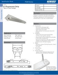
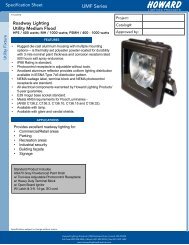
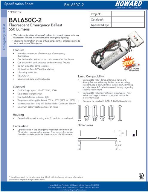
<strong>Spec</strong>ification <strong>Sheet</strong>BAL650C-2Emergency <strong>Ballast</strong>1/19/2012BAL650C-2Fluorescent Emergency <strong>Ballast</strong>650 Lumens• Works in conjunction with an AC ballast to convert new or existingfluorescent fixtures into unobtrusive emergency lighting• Maintains illumination of one or two lamps in the emergency modefor a minimum of 90 minutesFeatures• Provides a minimum of 90 minutes of emergencyillumination• Can be installed inside, on top or in remote* of the fixture• Can be used in both switched and unswitched fixtures• UL 924 Listed for damp location• UL listed for Retrofit/Field Installation• Life safety NFPA 101• NEC/OSHA• Meets most state and local codesElectrical• Dual Voltage Input 120V/277 VAC, 60Hz• Solid-state charger circuit• Test Switch/Power Indicator light• Temperature Rating (Ambient): 0ºC to 50ºC [32ºF to 122ºF]• Maintenance-free, long life, Sealed Nickel Cadmium Battery• Maximum battery recharge time: 24 hoursProject:Catalog#:Approved by:NEW!Lamp Compatibility• Compatible with 1-lamp, 2-lamp, 3-lamp and4-lamp fixtures with many ballast types includingstandard, rapid start, slimline, instant start, dimmingand electronic AC ballast – consult factory regardingspecific applications• Compatible with many different lamp types – referto back of page or contact customer service formore information• Can only be used with G24d & Gx24d base lampsLow VoltageLED Combo Switch!Housing• Painted-white steel housing with 2’ conduits on each endIllumination• Operates one in the emergency mode for a minimum of90 minutes – please refer to page 2 for more information.Provides a maximum initial lumen output of 650 LumensDimensions1.5”9.4”2.4”* Conditions apply for remote mounting. Check with the factory for more information.<strong>Spec</strong>ifications subject to change without notice.Howard Lighting Products | 580 Eastview Drive | Laurel, MS 39443(toll free) 800.956.3456 | (direct) 601.422.0033 | (fax) 601.422.1652www.HowardLightingProducts.com
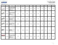
<strong>Spec</strong>ification <strong>Sheet</strong>BAL650C-2Emergency <strong>Ballast</strong>Lamp Compatibility DataProject:Catalog#:Approved by:<strong>Ballast</strong> Model No. No. Of BAL650C-2 BAL650C-4 BAL500 BAL700 BAL1400 BAL3000LampsLumen Ouput Operated 650 750 500 700 1400 3000LinearFluorescentLampsCompactFluorescentLamps<strong>Spec</strong>ialFluorescentLampsT8T10T124-PinCFL4-Pin LongCFL1 Lamp - 17-40 17-40 40-110 40-110 40-2152 Lamp - - - 17-40 17-40 17-401 Lamp - 17-40 17-40 - - -2 Lamp - - - 17-40 17-40 17-401 Lamp - 17-40 17-40 40-110 40-215 40-2152 Lamp - - - 17-40 17-40 17-401 Lamp - 40-42 13-39 40-42 40-42 -2 Lamp - 13-39 - 13-39 13-39 13-421 Lamp - 40-42 13-39 40-50 40-50 40-552 Lamp - 18-40 - 18-40 18-40 18-402-Pin CFL 1 Lamp 13-26 - - - - -T9 Circline 1 Lamp - 20 20-40 - - -CFL 2 Lamp - - - 20-40 20-40 20-40U-BentT81 Lamp - 32,40 32,40 - - -2 Lamp - - - 32,40 32,40 32,40T121 Lamp - 32,40 34,40 - - -2 Lamp - - - 34,40 34,40 34,40In applications involving 2, 3, or 4-lamp instant start ballasts, for 2-lamp emergency operation, only1 lamp will go dim in the test mode. When power is cut off to the fixtures, both lamps will come on(in EM Mode) as they are suppose to.<strong>Spec</strong>ifications subject to change without notice.Howard Lighting Products | 580 Eastview Drive | Laurel, MS 39443(toll free) 800.956.3456 | (direct) 601.422.0033 | (fax) 601.422.1652www.HowardLightingProducts.com
<strong>Spec</strong>ification <strong>Sheet</strong>BAL650C-2Installation InstructionsEmergency <strong>Ballast</strong>When using this lighting device the safety precautions should be followed at all times.PLEASE READ CAREFULLY AND FOLLOW ALL INSTRUCTIONS FOR YOUR OWN SAFETY1. This device is designed for indoor use. Do not use outdoors.2. Prior to installation, battery connector must be open to prevent high voltage from beingpresent on our put leads (red & yellow).3. This device is designed for use with One double twin-tube (quad) or one triple twin-tubecompact fluorescent lamp shown in the Lamp Rating Chart as follows:Lamp Rating Chart (Operates 1 Lamp)Twin-Tube CFL (2-pin) Triple-Tube CFL (2-pin)Wattage Base Wattage Base10, 13, 18,13, 18, or 26G24dGX24dor 26 wattswatts4. Please ensure the electrical connections conform to the National Electrical Code and localregulations if applicable.5. To avoid electric shock, please disconnect normal and emergency power supplies andbattery connector of the emergency ballast before servicing.6. This device is designed for factory or field installation in either the ballast channel or on topof the indoor fixtures. Do not install this device near gas or electric heaters.7. AC power source of 120VAC or 277VAC is required.8. The battery is sealed, non-maintenance, and is not replaceable in the field. Please contactmanufacturer for information on service. Do not attempt to service the battery please.9. Do not use accessory equipment that is not recommended by manufacturer. Failure to doso may cause unsafe conditions. Servicing should only be performed by qualified servicepersonnel.10. Do not use the product for other purpose that the product is NOT designed for.<strong>Spec</strong>ifications subject to change without notice.Howard Lighting Products | 580 Eastview Drive | Laurel, MS 39443(toll free) 800.956.3456 | (direct) 601.422.0033 | (fax) 601.422.1652www.HowardLightingProducts.com
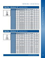
<strong>Spec</strong>ification <strong>Sheet</strong>BAL650C-2Installation InstructionsEmergency <strong>Ballast</strong>NOTE: All the branch circuit wiring has to be ready as well as an unswitched source of power before the fixture isinstalled. Confirm that the same branch circuit runs the emergency ballast and the AC ballast.CAUTION: Inverter connector has to be opened for preventing high voltage on output leads (red & yellow). Waituntil all the installation process is completed and AC is supplying power to the emergency ballast then join theinverter connector.1. AC power has to be off before installation.2. Choose the right wiring diagram to connect the emergency ballast to AC ballast and lamp.3. Follow diagram 1 to connect the emergency ballast and test plate. Please ensure the electricity connectionsconform to the National Electrical Code and local regulations if applicable. The emergency ballast install u to halfdistance the AC ballast manufacturer recommends install the AC ballast from the lamp or install within 50 feet isrecommended. Please choose the one in less distance. The emergency ballast could be mounted within 50 feetif there isn’t AC ballast.4. Cut the wire between the lamp holder and AC ballast and then connect the blue and blue/white wire fromemergency ballast to AC ballast and the yellow and yellow/black wires to the lamp holder.5. The emergency ballast has to be connecting to an unswitched 120VAC or 277VAC power source with noexception. Other voltages are not accepted!! Do not join the inverter connector until the fixture is completelyinstalled and supply AC power to the emergency ballast.6. An additional unswitched hot wire (120VAC or 277VAC) has to be run to the junction box and connected to theemergency ballast if there is in ON SWITCHED FIXTURES.7. The battery needs to be charged for one hour in order to have short-term testing on the emergency function.Before having a long-term emergency function testing, the battery in emergency ballast has to be charged for 24hours.8. Please search in readily visible location and stock the label with “CAUTION: This Unit Has More Than One PowerSupply Connection Point. To Reduce The Risk Of Electric Shock, Disconnect Both The Branch Circuit-Breakers OrFuses And Emergency Power Supplies Before Servicing.”9. See Diagrams 2 and 3 showing basic switched and unswitched fixture connections. See back page for moredetailed wiring schematics. The emergency ballast can be used with one- or two- multi-lamp fixtures; however, itonly operates one lamp in the emergency mode.NOTE: SWITCH BOX IS NOT SUPPLIEDOPERATION:THE CHARGING INDICATOR LIGHT WOULD BE ON TO INDICATE THE BATTERY IS BEING CHARGED WHEN ACPOWER IS APPLIED. THIS EMERGENCY BALLAST WOULD FUNCTION AND OPERATE ONE (OR TWO LAMPS ATREDUCED ILLUMINATION) WHEN THE AC POWER IS FAILED THE DEVICE OF THIS EMERGENCY BALLAST WILLOPERATE 10 WATT TO 26 WATT LAMPS AT LEAST 90 MINUTES.MAINTENANCE:NOTE: SERVICES SHOULD ONLY BE PERFORMED BY QUALIFIED PERSONNEL. THE EMERGENCYBALLAST SHOULD BE CHECKED PERIODICALLY TO CONFIRM FUNCTIONING AND THE FOLLOWINGSCHEDULE IS RECOMMENDED1) TO INSPECT THE CHARGING INDICATOR EVERY MONTH AND CONFIRM THAT IS ILLUMINATED.2) PUSH THE TEST SWITCH FOR 30 SECONDS TO ENSURE THE EMERGENCY BALLAST ISFUNCTIONING, RECOMMENDED TO PERFORM THIS TEST EVERY 30 DAYS.3) PERFORMING A LONG-TERM (90 MINUTE BATTERY DISCHARGE) IN EVERY YEAR. ONE OR TWOLAMPS SHOULD BE OPERATED FOR NO LESS THAN 90 MINUTES.<strong>Spec</strong>ifications subject to change without notice.Howard Lighting Products | 580 Eastview Drive | Laurel, MS 39443(toll free) 800.956.3456 | (direct) 601.422.0033 | (fax) 601.422.1652www.HowardLightingProducts.com