English version, please click here to download - Trellcan
English version, please click here to download - Trellcan
English version, please click here to download - Trellcan
- No tags were found...

You also want an ePaper? Increase the reach of your titles
YUMPU automatically turns print PDFs into web optimized ePapers that Google loves.
The primary function of Trelleborg Industrial AVS antivibrationmountings is <strong>to</strong> eliminate harmful vibration andeffectively reduce structure-borne sound. Our mission is <strong>to</strong> beour cus<strong>to</strong>mers’ preferred choice for engineered solutions inthe Industrial, Off-highway, Rail and Marine markets.Unrivalled resourcesTrelleborg Industrial AVS has all the resources you wouldexpect from a global market leader:• An R&D centre and purpose-built, state-of-the-art manufacturingplant at our Leicester head office in the UK,plus production facilities in Sweden.• Our own labora<strong>to</strong>ries equipped with the very latest compoundformulation, modelling and simulation technologiesfor material and product development.• An advanced mixing facility <strong>to</strong> prepare compound on siteunder clean and rigorously controlled conditions.Total solutionsTrelleborg Industrial AVS provides far more than optimumtechnical solutions based on computer-managed calculations.Our overall approach <strong>to</strong> solving vibration problemsencompasses:• Education and training in vibration techniques <strong>to</strong> increaseunderstanding and knowledge of vibration problems.• World-class testing facilities including a comprehensiveprogram of static, dynamic and fatigue testing at our technicalcentre in Leicester.• Advanced simulation techniques such as Finite ElementAnalysis (FEA) and multi body vibration analysis software<strong>to</strong> simulate the loads that products have <strong>to</strong> withstandover a full service life.Continuous developmentWe have developed the special TrellExtreme ® range for theoff-highway market, but we don’t s<strong>to</strong>p t<strong>here</strong>:• We invest continuously in the development of our productsand the materials we use.• Our labora<strong>to</strong>ries continually measure and control specificationsof raw materials and finished products.• And, as a member of the Trelleborg group, TrelleborgIndustrial AVS is in a position <strong>to</strong> fully control the completeproduction process and all vital raw materials.Environmental improvementOur aim is <strong>to</strong> exceed the requirements of current and futureenvironmental legislation and set a standard for others <strong>to</strong>follow:• We constantly review our manufacturing processes in thedrive for year-on-year environmental improvement.• Our strategy includes the continued elimination of solvents,significantly reducing emissions in<strong>to</strong> the atmosp<strong>here</strong>,water purification and decreasing notifiable waste.• In our industry we lead the way in the increased use ofaqueous metal degreasing methods, water-based bondingagents and protective finishes.Overcoming complexityVibration problems are often complicated. We assist ourcus<strong>to</strong>mers every step of the way:• Our technical department helps cus<strong>to</strong>mers evaluatespring mass systems in order <strong>to</strong> achieve ideal solutions<strong>to</strong> specific vibration problems.• The advanced computer programs we use are designed incooperation with technical universities.• Specialists in design engineering and product developmentwork alongside cus<strong>to</strong>mers <strong>to</strong> ensure a successfulproject outcome: products with outstanding performancebenefits.Promoting insightTrelleborg Industrial AVS offers <strong>to</strong>p-grade trainingand testing in its field:• Analysis using FFT technology – we cantake measurements, analyze the applicationand recommend the best solution.• Our technical centre’s advanced testingfacilities give Trelleborg IndustrialAVS an excellent platform forproduct development.• We conduct training andeducation courses for cus<strong>to</strong>mersand distribu<strong>to</strong>rs <strong>to</strong>increase awareness ofvibration issues andTrelleborg IndustrialAVS solutions.5
A cost-effective cureThe manufacturing costs related <strong>to</strong> accurate balancing ofmachines are very high and may rise quickly with increasedinner balancing. As vibration isolation of the entire machinemay still have <strong>to</strong> be considered, Trelleborg Industrial AVSantivibration mountings can be cost-effective by reducing theneed for intensive balancing.Rubber springs <strong>to</strong> the rescueVibration isolation is based on installing machinery on springsor resilient material of known stiffness and damping. The mostcommonly used spring materials are rubber and steel. Anotheralternative is air springs. However, the properties of rubbermake it particularly suitable as a spring material, as it has:• A high load bearing capacity with an ability <strong>to</strong> accommodateoverload conditions without the catastrophic failuresassociated with steel and other materials.• The ability <strong>to</strong> carry complex loadings more easily andeconomically than other alternatives. By bonding rubber<strong>to</strong> a rigid material, a product can be created <strong>to</strong> accommodatemovement with no sliding or rotating surfaces thatrequire lubrication. This allows operation in many harshenvironments with substantially reduced maintenancerequirements.Components can be designed <strong>to</strong> integrate with the spacelimitations of the application and provide control in all sixmodes of freedom. Steel springs are normally used in the formof coil springs or leaf springs. Although steel springs permitrelatively high deflections, they provide very little damping.Consequently, excessive movement occurs when passingthrough the resonance range. Often special devices are installedin order <strong>to</strong> limit deflections. To allow their properties <strong>to</strong> beutilized in a satisfac<strong>to</strong>ry way, Trelleborg Industrial AVS rubbermountings are available in various hardness grades and polymertypes.7
tial contaminates must be considered. Most Trelleborg rubbercompounds are based on natural rubber compunds, offeringhigh strength and excellent performance characteristics. A rangeof synthetic rubber compounds is also available for special applicationsw<strong>here</strong> resistance <strong>to</strong> continuous high temperatures(>60 °C) or other harsh environmental conditions is required.Anti-oxidants and anti-ozonants are included in manyformulations <strong>to</strong> provide resistance against ozone and ultra violetrays.Dynamic elasticityDynamic loadStatic loadDeformationFIG.6. Schematic representation of the internal damping properties of rubber.The elliptical area indicates the loss of energy.FIG.5. Response of single impact applied <strong>to</strong> steel and rubber springs.Spring coefficientsA rubber spring has different characteristics for static anddynamic conditions. A constant load causes a deflection, andthe inclination/deflection gives the static spring coefficient.When the spring at static equilibrium is loaded with a dynamicforce, the response is a higher spring coefficient.Static StiffnessThe stiffness of a spring is a measure of applied force (P)againsta resulting Deflection (X). Measurements taken at a continuousfeed rate (usually in the order of 1mm/sec velocity)providestatic (or pseudo static)characteristic. The curves in fig. 7 showalternative methods of determining stiffness.FORCEFORCERANGERANGEDEFLECTIONRANGERANGEFORCEFORCEStifness = dP/dX at X.PDEFLECTIONDEFLECTIONFIG.7. dP/dX at XP average gradient over P (or X) range (usually derived by least squares method of curve fitting).9
Dynamic StiffnessThe stiffness of a rubber spring changes when a dynamic forceis applied. This is known as the dynamic (or complex) stiffness.The dynamic stiffness is usually higher than the pseudo-staticstiffness, (the difference being referred <strong>to</strong> as the dynamic <strong>to</strong>static ratio) and is affected by several fac<strong>to</strong>rs including changesin frequency, temperature and amplitude. See fig. 8. Thedynamic stiffness is considered <strong>to</strong> be unchanged between 5Hzand 80Hz under constant conditions. Above this frequencyrange, the dynamic stiffness of the spring will deviate fromthe ideal ‘massless ’spring stiffness. This is due <strong>to</strong> the masseffects of standing waves. “Wave effect ”changes of dynamicstiffness are generated when the rubber section dimensionsbecome comparable with multiples of the half wavelength ofthe propagated wave passing through the spring. Calculationsof the deviation from ideal “massless ” spring dynamic stiffnessdue <strong>to</strong> wave effect are complex and are normally obtained fromtest measurement. A typical stiffness curve for a large sectionrubber <strong>to</strong> metal bonded spring is shown below. In fig. 9.LOADFIG.8dbref 1N/MDEFLECTIONHIGH FREQUENCY DYNAMIC STIFFNESSKs = P 1X 1– X 5K d=P 3– P 4X 3– X 4Creep PerformanceWhen a rubber spring is subjected <strong>to</strong> a constant load, the resultantdeflection continues <strong>to</strong> increase with time. An exampleof creep that occurs in a pair of inclined springs is shown onthe graph in fig.10. A typical creep characteristic for rubberused in antivibration mountings is 3-5% per time decade.Joule effectChanges in temperature cause small changes in the deflectionof loaded rubber springs. This change in deflection, which isreversible with temperature, is known as the Joule effect. Forpairs of springs shown a 10 °C rise in temperature will causean increase in clearance by approximately 4.5% of thenominal static deflection. See fig. 11 and 12.FIG.9FIG. 10CREEP - % INCREACE ON BASE DEFLECTIONFREQUENCY (Hz)TIME - DAYSLADENCLEARENCEFREE% CHANGE DeflectionTempC˚TempC˚Gradient 4,5 %change in deflectionper 10˚CFIG. 11 FIG. 12% CHANGE Deflection10
Stiffnes of a rubber springWhen calculating compression characteristics of rubber, itshould be noted that the deflection is not directly proportional<strong>to</strong> the load, as the modulus of elasticity in compressionincreases with the degree of stress. The modulus of shear,however, remains constant for normal stresses. The fac<strong>to</strong>r withthe most effect on stiffness is the ratio between loaded andfree surface area of rubber. This is the so-called shape fac<strong>to</strong>r(often designated S). With thin rubber sections,a very highmodulus of elasticity can be achieved. The stiffness of a rubberspring is also determined by the dimensions and the hardnessof the rubber. Fig. 13 illustrates the relationship between rubberhardness and shear modulus, and Fig.14 the dependence ofthe bulk modulus on the shape fac<strong>to</strong>r. The latter curve appliesat 10% deformation. The curves show that rubber at a shapefac<strong>to</strong>r of 0.25 for shear i about 6-8 times softer thancompression for the same rubber hardness. Since only 3-4 timesthe stress value in compression can be considered, it may besaid that rubber is best used in shear <strong>to</strong> achieve large deflectionsand good isolation properties, particularly at low interferencefrequencies.Selection of antivibration mountingsThe principle relating <strong>to</strong> vibration isolation with springs isthat they are placed between source and receiving structures.To ensure effective isolation, the springs must be selectedcarefully, otherwise the result could be impaired performance.In favourable cases, the transmitted force can be reduced <strong>to</strong>only 2 or 3% of that of a rigidly mounted machine. In suchcases, the vibrations are practically eliminated.HardnessIRHStatic E-modulus MPaHardnessIRH60State shear modulusShape fac<strong>to</strong>r, SFIG.13 Relationship between rubber hardness and shear modulus.FIG.14 The dependence of the compression modulus upon the shape fac<strong>to</strong>r.SOME VIBRATION DEFINITIONSAmplitude A (m) The magnitude of the displacement of a vibration deflection from themean position. The <strong>to</strong>tal vibration is thus twice the amplitude.Interference frequency f (Hz) Is essentially the same as the frequency of the rotational speed of themachine or a harmonic.Natural Frequency f o(Hz) The number of vibrations in a freely-oscillating system per unit of time.Mass m (Kg) The mass of the oscillating system.Spring force F (N) The force emanating from a spring on the machine or the reverse.Deflection d (m) The deformation of the spring from the neutral position.Static spring stiffness Kstat (N/m) The force required in New<strong>to</strong>ns <strong>to</strong> compress the mounting 1 m.Dynamic spring stiffness Kdyn (N/m) Spring stiffness when an alternating force is applied.Tuning ratio Z (-) The ratio between interference frequency f and natural frequency fo .Interference force F (N) The force transmitted <strong>to</strong> the base of an isolated machine.Impulse force F i (N) The force transmitted <strong>to</strong> the base of a rigidly mounted machine.Magnification fac<strong>to</strong>r B (-) The part of the impulse force which is transmitted as a vibration force.Indicates the relation between the interference force F and impulse force F i .Level of isolation I (-) The part of the impulse force which is eliminated by the vibration isolation,(1-B)or, if B is expressed as a percentage, (100-B).Damping coefficient c (Ns/m) The linear viscous damping coefficient.Critical damping c kr (Ns/m) The linear viscous damping coefficient at critical damping. A system is said <strong>to</strong>be critically damped if it returns <strong>to</strong> its initial static position without anyover-oscillation after a displacement.Damping fac<strong>to</strong>r D (-) The ratio between c and ckr.Reduction R (dB) Isolation expressed in decibels.Deflection stat (mm) The static deflection for a spring.11
ASSISTANASSISTANCE GUIDE WHEN CHOOSCONSTRUCTION C O N S T R U C T I O N E EQUIPMENTQ U I P M E N TP R O D U C TA P P L I C A T I O NMDS MOUNTING ENGINE, CAB 16P A G EMETACONE ENGINE, CABIN, RADIATOR 18HYDROMOUNTING CAB 26COMPACTOR SHEARMOUNTING VIBRATORY COMPACTORS 27CUSHYFLOAT SPECIAL ENGINE 28CAB MOUNTING ENGINE, CAB 302-PIECE CR MOUNTING ENGINE ,CAB 32EH ENGINE ,CAB, RADIATOR 34MUSHROOM ENGINE, CAB, RADIATOR 36SPHERILASTIK SUSPENSION 39CONTROL LINK SUSPENSION 40CONICAL BEARING SUSPENSION 41SUSPENSION SPRING SUSPENSION 42P R O D U C TAGRICULTUREA G R I C U L T U R EA P P L I C A T I O NMDS MOUNTING ENGINE, CAB 16P A G EMETACONE ENGINE, CAB, RADIATOR 18HYDROMOUNTING CABIN 2614
MDSNote: e natural frequencies and degrees of isolation are based on dynamic characteristics of the mountings.Loadper mounting (kg) Trelleborg Industrial AVS operates a policy of continuous improvement and development. We reserve the right <strong>to</strong> change design and specification of our products without prior notification or alteration of literature.We will not be held responsible for any danger or damage incurred through improper use or installation.17
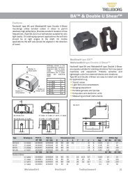
Metacone & HKFeaturesA compact fail safe design, available for a wide range of loadingwith in some cases alternative fixings.Cu<strong>to</strong>uts in rubber section on various sizes provide differentvertical/horizontal stiffness ratios.InstallationSuspended unitMetacone and HKA range of mountings designed for high load capacity with relativelylarge static deflections. e high loading for a given size isachieved by utilizing the rubber <strong>to</strong> best advantage in shear andcompression. Normally, mountings are assembled with overloadand rebound washers <strong>to</strong> control and limit movement of thesuspended equipment under shock loads. Center fixing boltsshould be <strong>to</strong>rque tightened <strong>to</strong> the recommended values.Frame17-1690 17-0241 17-1629 17-0379Ø6052 50.8 32.730Ø25.41216.22.6L20.510.3 30.23.5 8.247.627 22Ø52Ø12212.34950.8Ø56Ø12.710.2Ø50Ø10.2292xø\C7;10.354Ø10.3xx702xø\C7;8.753.9Ø8.75782.5101.625.476.282.510217-0248 (solid) L=4217-0241 (x cut out) L=4217-0189 (solid) L=517388.97389Bolt Max. Bolt Max* Load Top Washer Bot<strong>to</strong>m WasherType Part no. Size Torque Nm kg Part no. Part no.17-0189-45 10-00365-01 M12 40 95 20-00529-01 20-00038-0117-0189-70 10-00367-01 M12 40 275 20-00529-01 20-00038-0117-0241-45 10-00374-01 M12 40 45 20-00529-01 20-00038-0117-0241-60 10-00375-01 M12 40 90 20-00529-01 20-00038-0117-0248-45 10-00379-01 M12 40 90 20-00529-01 20-00038-0117-0248-60 10-00380-01 M12 40 175 20-00529-01 20-00038-0117-0379-45 10-00402-01 M10 25 25 20-00531-01 20-00531-0117-0379-60 10-00404-01 M10 25 50 20-00531-01 20-00531-0117-1629-45 10-00941-01 M10 25 35 20-00531-01 10-03724-0117-1629-60 10-00942-01 M10 25 65 20-00531-01 10-03724-0117-1690-50 10-00752-01 M12 90 125 20-00416-01 20-00536-0117-1690-70 10-00751-01 M12 90 210 20-00416-01 20-00536-01(*) Max. loads have been calculated for extreme off-highway use, these are lower values than shown in the industrial catalogue.18Trelleborg Industrial AVS operates a policy of continuous improvement and development. We reserve the right <strong>to</strong> change design and specification of our products without prior notification or alteration of literature.We will not be held responsible for any danger or damage incurred through improper use or installation.
Metacone & HKNote: e natural frequencies and degrees of isolation are based on dynamic characteristics of the mountings.Loadper mounting (kg) Trelleborg Industrial AVS operates a policy of continuous improvement and development. We reserve the right <strong>to</strong> change design and specification of our products without prior notification or alteration of literature.We will not be held responsible for any danger or damage incurred through improper use or installation.19
Metacone & HKNote: e natural frequencies and degrees of isolation are based on dynamic characteristics of the mountings.Loadper mounting (kg) Trelleborg Industrial AVS operates a policy of continuous improvement and development. We reserve the right <strong>to</strong> change design and specification of our products without prior notification or alteration of literature.We will not be held responsible for any danger or damage incurred through improper use or installation.21
Metacone & HK17-0566 17-0391 17-1032 17-1843Ø84Ø38Ø84Ø3884.138.1Ø100Ø4610333.6 26 64 67771 746.933.334 8070.6Ø75Ø16.3Ø10.3Ø75Ø16.3Ø10.316.3Ø93Ø2074.6Ø1282.7 10582.7 1052xø\C7;13.510988.969.49269.492114.3139.712715617-1227 17-0146Ø81Ø34.94.7163.779.4Ø116Ø47.617120Ø60.5Ø75Ø20.4Ø10.3Ø10Ø73.3Ø95A - AØ25Lower end of outermetal must besupported as shown.82.7 10598.4 1211A69.491.7A98.4Bolt Max. Bolt Max* Load Top Washer Bot<strong>to</strong>m WasherType Part no. Size Torque Nm kg Part no. Part no.17-0146-45 10-00360-01 M24 200 685 20-00527-01 20-00031-0117-0146-60 10-00361-01 M24 200 1285 20-00527-01 20-00031-0117-0391-45 10-00411-01 M16 135 250 20-00532-01 20-00532-0117-0391-60 10-00414-01 M16 135 470 20-00532-01 20-00532-0117-0391-70 10-00415-01 M16 135 720 20-00532-01 20-00532-0117-1032-45 10-02905-01 M16 135 250 20-00532-01 20-00532-0117-1032-60 10-02977-01 M16 135 470 20-00532-01 20-00532-0117-1032-70 10-03726-01 M16 135 720 20-00532-01 20-00532-0117-0566-45 10-00433-01 M16 135 165 20-00532-01 20-00532-0117-0566-60 10-00434-01 M16 135 310 20-00532-01 20-00532-0117-0566-70 10-00435-01 M16 135 495 20-00532-01 20-00532-0117-1227-45 10-00459-01 M20 180 425 20-00528-01 20-00036-0117-1227-60 10-00460-01 M20 180 850 20-00528-01 20-00036-0117-1843-45 10-00609-01 M24 160 250 20-00533-01 20-00533-0117-1843-60 10-00610-01 M24 160 460 20-00533-01 20-00533-01(*) Max. loads have been calculated for extreme off-highway use, these are lower values than shown in the industrial catalogue.22Trelleborg Industrial AVS operates a policy of continuous improvement and development. We reserve the right <strong>to</strong> change design and specification of our products without prior notification or alteration of literature.We will not be held responsible for any danger or damage incurred through improper use or installation.
Metacone & HKNote: e natural frequencies and degrees of isolation are based on dynamic characteristics of the mountings.Loadper mounting (kg) Trelleborg Industrial AVS operates a policy of continuous improvement and development. We reserve the right <strong>to</strong> change design and specification of our products without prior notification or alteration of literature.We will not be held responsible for any danger or damage incurred through improper use or installation.23
Metacone & HKNote: e natural frequencies and degrees of isolation are based on dynamic characteristics of the mountings.Loadper mounting (kg) Trelleborg Industrial AVS operates a policy of continuous improvement and development. We reserve the right <strong>to</strong> change design and specification of our products without prior notification or alteration of literature.We will not be held responsible for any danger or damage incurred through improper use or installation.25
Compac<strong>to</strong>r ShearmountFeatures– High tensile strength superior grade rubber compoundsbonded <strong>to</strong> steel mounting plates.– Compact and easy <strong>to</strong> install, maintenance free.– Can be used in pairs in an angled arrangement, loaded incombined compression and shear <strong>to</strong> optimize vibration isolationperformance.Trellextreme Compac<strong>to</strong>r Shearmountings support high compressiveloads with low shear stiffness.ey are suitable for suspension of vibra<strong>to</strong>ry compac<strong>to</strong>r drumson compac<strong>to</strong>r roller vehicles and vibra<strong>to</strong>ry screen equipment.2 “& 3” BR 3.00dLHBLAKtHd2 & 3” shear / compression MountingsDimension Compression Shear weightType Part no. A B K L H d t Max load (kg) deflection (mm) Max load (kg) deflection (mm) kg2” -55 10-01798-01 100 85 120 110 60 11 5 670 9 70 7,5 1,12” -60 10-01618-01 100 85 120 110 60 11 5 840 9 90 7,5 1,12” -65 10-01619-01 100 85 120 110 60 11 5 1010 9 100 7,5 1,13” -55 10-00067-01 146 146 182 182 76 13 7,5 2000 11 220 13 3,43” -60 10-00065-01 146 146 182 182 76 13 7,5 2500 11 280 13 3,43” -65 10-00066-01 146 146 182 182 76 13 7,5 3000 11 340 13 3,4BR 3.00-45 20-01038-01 100 63 M12 180 3,0 85 9,0 0,35BR 3.00-55 20-01039-01 100 63 M12 275 3,0 125 9,0 0,35BR 3.00-60 20-01040-01 100 63 M12 340 3,0 155 9,0 0,35Trelleborg Industrial AVS operates a policy of continuous improvement and development. We reserve the right <strong>to</strong> change design and specification of our products without prior notification or alteration of literature.We will not be held responsible for any danger or damage incurred through improper use or installation.27
Cushyfloat SpecialFeaturese design incorporates bump and rebound control features,which limit excessive movements under shock loading.Top metal cover gives protection against oil contamination.Protective finish resists corrosion attack.Metalastik® Cushyfloat special is designed for rough offhighway environment. Used on engines for small ADT andExcava<strong>to</strong>r etc.17-2153 Typical Static Vertical Stiffness1,210,8LOAD-kNTension0,60,4Compression0,2-3 -2 -100-0,21 2 3 4 5 6 7 8-0,4-0,6-0,8-1-1,2DEFLECTION - mm17-1600 17-2153High Damping CushyfloatWith Increased ReboundM1238ReboundBufferHigh DampingRubber Compound1001206 mm limit s<strong>to</strong>pCushyfloat specialMax. Bolt Max. LoadType Part no. Torque Nm kg Comments17-1600-11 10-00738-01 25 35 medium damping17-1600-25 10-00933-01 25 35 High damping17-1600-26 10-00934-01 25 55 High damping17-1600-27 10-02624-01 25 35 High damping - vertical downwards limit s<strong>to</strong>p17-2153-00 10-00987-01 25 35 High damping - moulded rebound buffer17-2153-01 10-01045-01 25 55 High damping - moulded rebound buffer28Trelleborg Industrial AVS operates a policy of continuous improvement and development. We reserve the right <strong>to</strong> change design and specification of our products without prior notification or alteration of literature.We will not be held responsible for any danger or damage incurred through improper use or installation.
Cushyfloat SpecialNote: e natural frequencies and degrees of isolation are based on dynamic characteristics of the mountings.Loadper mounting (kg) Trelleborg Industrial AVS operates a policy of continuous improvement and development. We reserve the right <strong>to</strong> change design and specification of our products without prior notification or alteration of literature.We will not be held responsible for any danger or damage incurred through improper use or installation.29
8Cab Mounting201570˚ IRHLoad kN1060˚ IRH545˚ IRH321Specially profiled rubber sections <strong>to</strong>gether with bump andrebound washers provide optimum cab suspension and vibrationisolation characteristics.1 2 3 4 5 6 7 8Deflection mm17-0890Typical applications on off-highway vehicles are cabs but alsoon engine transmissions.17-1650, 17-1997, 17-1814 Application sampleD17-08905490d70H2H1HED1C+0.569.8167090INSTALLATION ARRANGEMENT 11-1027, 11-1028ø10.3AABB11-1027, 11-102880EQUIPMENTBRACKETWASHERWASHERR1.516NO RADIUSREQUIREDC60.460.0MOUNTING HOLESUPPORTSTRUCKTUREALTERNATIVEDimension Bolt Max. Bolt Max. Load Top & Bot<strong>to</strong>mType Part no. D D1 d H H1 H2 E C Size Torque Nm kg Washer Part no.11-1027-45 20-01107-01 80 59 20,3 58 40 20 16 60 M20 380 75 20-00003-0111-1027-60 20-01108-01 80 59 20,3 58 40 20 16 60 M20 380 150 20-00003-0111-1028-45 20-00875-01 80 59 16,3 58 40 20 16 60 M16 250 75 20-00532-0111-1028-60 20-01109-01 80 59 16,3 58 40 20 16 60 M16 250 150 20-00532-0117-1650-45 10-00552-01 105 75 22 55 46 19 20 75 M20 180 190 20-00533-0117-1650-60 10-00944-01 105 75 22 55 46 19 20 75 M20 180 350 20-00533-0117-1997-45 10-00626-01 105 75 16,5 55 46 19 20 75 M16 180 190 20-01494-0117-1997-60 10-00627-01 105 75 16,5 55 46 19 20 75 M16 180 350 20-01494-0117-1814-45 10-00598-01 120 89 25 62 47 13 25 89 M24 270 350 20-00534-0117-1814-60 10-00603-01 120 89 25 62 47 13 25 89 M24 270 800 20-00534-0117-0890-45 10-00440-01 M16 250 300 20-00532-0117-0890-60 10-00441-01 See Drawing M16 250 500 20-00532-0117-0890-70 10-00442-01 M16 250 750 20-00532-0130Trelleborg Industrial AVS operates a policy of continuous improvement and development. We reserve the right <strong>to</strong> change design and specification of our products without prior notification or alteration of literature.We will not be held responsible for any danger or damage incurred through improper use or installation.
2-piece CR mountingFeaturesWith washer it is a compact fail-safe design easy <strong>to</strong> fit with asingle bolt.– Integral bonded steel flange prevents rubber wear at interfacewith bracket.– No radius or chamfer required for installation hole.– 2-piece design gives excellent isolation performance andrebound control during shock loading of the vehicle.CR-Controlled Rebound mountingA range of mounting designed for high load capacity and lowinstallation height. e high loading for a given size is achievedby utilizing the rubber <strong>to</strong> best advantage in shear and compression.– Off-highway engines and CabsCR MountingDH1Typical installationEquipmentbracketHdD1EFrameCDimension (mm) Bolt Max. Bolt Max. Load WasherType Part no. D D1 d H H1 E C ±0,2 Size Torque Nm kg Part no.17-2190-45 20-01110-01 65 37,8 16 23,3 15,1 12 37,9 M16 170 75 20-01495-0117-2190-60 20-01111-01 65 37,8 16 23,3 15,1 12 37,9 M16 170 100 20-01495-0117-2178-45 20-02506-01 94 55,5 16 28 19 20 56,0 M16 250 115 20-01494-0117-2178-60 10-03729-01 94 55,5 16 28 19 20 56,0 M16 250 210 20-01494-0117-1984-45 10-03727-01 100 60 22 38 25,8 25 60,5 M22 500 260 20-01493-0117-1984-60 10-03728-01 100 60 22 38 25,8 25 60,5 M22 500 400 20-01493-0117-1931-45 10-00622-01 118 75,5 20 38,3 26,4 25 76,0 M20 500 225 20-01493-0117-1931-60 10-00623-01 118 75,5 20 38,3 26,4 25 76,0 M20 500 430 20-01493-0111-1029-45 10-03722-01 115 63 27 45 33,5 25 64,0 M24 700 550 20-00534-0111-1029-60 10-00793-01 115 63 27 45 33,5 25 64,0 M24 700 900 20-00534-0132Trelleborg Industrial AVS operates a policy of continuous improvement and development. We reserve the right <strong>to</strong> change design and specification of our products without prior notification or alteration of literature.We will not be held responsible for any danger or damage incurred through improper use or installation.
2-piece CR mountingNote: e natural frequencies and degrees of isolation are based on dynamic characteristics of the mountings.Loadper mounting (kg) Trelleborg Industrial AVS operates a policy of continuous improvement and development. We reserve the right <strong>to</strong> change design and specification of our products without prior notification or alteration of literature.We will not be held responsible for any danger or damage incurred through improper use or installation.33
EHFeaturesType EH is designed primarily for mobile applications w<strong>here</strong>high dynamic and shock forces are encountered.Dynamic vertical movements in both the directions are restrictedand excellent horizontal stability is provided.e function of EH includes features as:– Dynamic efficiency in all directions– Attenuation of structure-borne noise– Accommodation of misalignment and dis<strong>to</strong>rtion– Simple design-easy <strong>to</strong> install– Fail-safe installation– Wide load range, 60 <strong>to</strong> 350 kgType EH mountings are designed <strong>to</strong> achieve effective vibrationisolation on engines, opera<strong>to</strong>r cabins other ancillary units.dDTypical applications:– Off-highway vehicles– Military vehicles– Construction equipment– Material handling vehicles– Agriculture vehicleHH 2H 3H 4D 1H 1Example of installationExample of installationREC R ECMachine in operationMachine in operationTable of dimensions for installationDimension mm Bolt Max. Bolt Max.* Axial Top & Bot<strong>to</strong>mType Part no. d D D H H1 H2 H3 H4 C E R Size Torque Nm Load kg Washer Part no.EH 4850-40 NR 20-00621-01 13 50 32 50 20 10 20 20 31,0 15,0 1,5 M12 40 60 20-00416-01EH 4850-60 NR 20-00620-01 13 50 32 50 20 10 20 20 31,0 15,0 1,5 M12 40 100 20-00416-01EH 6463-40 NR 20-00619-01 17 64 40 62 23 14 25 23 39,0 22,0 2,3 M16 80 90 20-01495-01EH 6463-60 NR 20-00618-01 17 64 40 62 23 14 25 23 39,0 22,0 2,3 M16 80 200 20-01495-01EH 9075-40 NR 20-00617-01 23 89 58 73 25 19 29 25 56,5 28,0 3,0 M22 200 200 20-00533-01EH 9075-60 NR 20-00616-01 23 89 58 73 25 19 29 25 56,5 28,0 3,0 M22 200 350 20-00533-01ChloropreneEH 4850-40 CR 20-01504-01 13 50 32 50 20 10 20 20 31,0 15,0 1,5 M12 40 60 20-00416-01EH4850-60 CR 20-01510-01 13 50 32 50 20 10 20 20 31,0 15,0 1,5 M12 40 100 20-00416-01EH 6463-40 CR 20-01505-01 17 64 40 62 23 14 25 23 39,0 22,0 2,3 M16 80 90 20-01495-01EH 6463-60 CR 20-01506-01 17 64 40 62 23 14 25 23 39,0 22,0 2,3 M16 80 200 20-01495-01EH 9075-40 CR 20-01507-01 23 89 58 73 25 19 29 25 56,5 28,0 3,0 M22 200 200 20-00533-01EH 9075-60 CR 20-01508-01 23 89 58 73 25 19 29 25 56,5 28,0 3,0 M22 200 350 20-00533-01(*) Max. loads have been calculated for extreme off-highway use, these are lower values than shown in the industrial catalogue.34Trelleborg Industrial AVS operates a policy of continuous improvement and development. We reserve the right <strong>to</strong> change design and specification of our products without prior notification or alteration of literature.We will not be held responsible for any danger or damage incurred through improper use or installation.
EHNote: e natural frequencies and degrees of isolation are based on dynamic characteristics of the mountings.Loadper mounting (kg) Trelleborg Industrial AVS operates a policy of continuous improvement and development. We reserve the right <strong>to</strong> change design and specification of our products without prior notification or alteration of literature.We will not be held responsible for any danger or damage incurred through improper use or installation.35
Mushroom MCRFeaturesMushroom Controlled Rebound-MCR mountings are designedfor mobile accessories application such as muffler, radia<strong>to</strong>r,pumps etc. w<strong>here</strong> the disturbing frequencies are high.– Easy <strong>to</strong> install, single part mount– Can be used as resilient mount <strong>to</strong> take up small bracket andchassis misalignments.– Provides isolation of high frequency vibrations and shockprotection of vehicle mounted equipment.Dimension (mm) Bolt Max. Bolt Max. Axial Top & Bot<strong>to</strong>mType Part no. D d D1 H H1 H2 E C±0,2 R Size Torque Nm Load kg Washer Part no.MCR 27/1908-45 20-01129-01 27,5 10,0 20,0 25,5 15,5 5,0 8,0 19,0 1,5 M10 30 40 20-00531-01MCR 27/1908-60 20-00831-01 27,5 10,0 20,0 25,5 15,5 5,0 8,0 19,0 1,5 M10 30 55 20-00531-01MCR 45/2810-45 20-00782-01 45,0 13,0 31,5 32,0 25,0 10,0 10,0 28,5 1,5 M12 50 80 20-00416-01MCR 45/2810-60 20-01137-01 45,0 13,0 31,5 32,0 25,0 10,0 10,0 28,5 1,5 M12 50 150 20-00416-01MCR 51/3216-45 20-01133-01 51,8 13,5 34,0 41,0 35,0 13,5 16,0 31,8 1,5 M12 50 80 20-00536-01MCR 51/3216-60 20-01134-01 51,8 13,5 34,0 41,0 35,0 13,5 16,0 31,8 1,5 M12 50 180 20-00536-01MCR 64/3820-45 20-00833-01 64,0 16,0 41,0 50,0 43,0 16,0 20,0 38,0 3,0 M16 135 190 20-01495-01MCR 64/3820-60 20-01130-01 64,0 16,0 41,0 50,0 43,0 16,0 20,0 38,0 3,0 M16 135 380 20-01495-01MCR 75/4624-45 20-01135-01 75,0 16,0 50,0 56,0 50,0 21,0 23,5 46,0 3,0 M16 135 200 20-00532-01MCR 75/4624-60 20-01136-01 75,0 16,0 50,0 56,0 50,0 21,0 23,5 46,0 3,0 M16 135 400 20-00532-01MCR 95/5119-45 20-01131-01 95,0 21,0 57,0 63,0 51,0 25,0 19,1 50,8 3,0 M20 135 320 20-00533-01MCR 95/5119-60 20-01132-01 95,0 21,0 57,0 63,0 51,0 25,0 19,1 50,8 3,0 M20 135 625 20-00533-0136Trelleborg Industrial AVS operates a policy of continuous improvement and development. We reserve the right <strong>to</strong> change design and specification of our products without prior notification or alteration of literature.We will not be held responsible for any danger or damage incurred through improper use or installation.
Suspension rangeSuspension SystemsConical BearingSpherilastikSuspension SpringSpherilastikControl Link38Trelleborg Industrial AVS operates a policy of continuous improvement and development. We reserve the right <strong>to</strong> change design and specification of our products without prior notification or alteration of literature.We will not be held responsible for any danger or damage incurred through improper use or installation.
Spherilastik BearingsFeatures/ApplicationsA heavy-duty flexible bearing which combines high-load carryingcapacity with the ability <strong>to</strong> accommodate <strong>to</strong>rsional andangular movements in all planes without lubrication and metal<strong>to</strong>-metalwear.Typical use include traction and braking reaction rods for offroadvehicles, hydraulic damper fixings and other applicationsw<strong>here</strong> a high duty bearing of compact size is required.Spherilastik bearings, centre bore typeSpherilastik bearings, trunnion typeGeneral guidance notes for selection:1. Properties quoted for the components in this leaflet relate <strong>to</strong> continuous steady loading or deformationconditions.2. For continuous dynamic cyclic loading or deformation, the maximum values should be reduced<strong>to</strong> approximately 30% of the figures quoted, depending on frequency.3. For medium and low incidence loading and deformation, the tabled values may be increased up<strong>to</strong> 2 <strong>to</strong> 3 times.4. Combined stressing in the different modes and the effects of stress reversals may require a morecritical assessment.Radial Torsion Conical RecommendedDimensions in mm Stiffness Max. Load Stiffness +/- beta Stiffness +/- alpha Weight HousingType Part no. d D A B E F G kN/mm kN kNn/rad degrees kNm/rad degrees (kg) Diameter (mm)Centre Bore 10-00237-01 28,6 90,5 70,0 76,2 93 58 2,8 8 2,8 6 2,5 90.475 / 90.513Centre Bore 10-01099-01 44,5 127,0 101,6 104,8 87 93 6,8 7 6,2 7 6,4 126.98 / 127.04Centre Bore 10-00273-01 50,1 127,0 101,6 104,8 260 220 15 6 13 5 6,3 126.98 / 127.04Centre Bore 10-03723-01 37,1 150,0 120,0 140,0 150 205 12 8 11 8 8,0 150.02 / 150.07Centre Bore 10-03078-01 31,3 127,0 101,6 120,0 87 93 6,8 7 6,2 7 6,4 126.98 / 127.04Trunnion 10-00878-01 48,0 90,6 70,0 170,0 30,0 130,0 20,5 90 58 2,8 8 2,8 6 3,0 90.47 / 90.51Trunnion 10-00304-01 50,5 104,8 76,2 170,0 30,0 130,0 19,0 220 150 4,5 8 7,5 6 5,8 104.76 / 104.80Trunnion 10-03615-01 50,5 104,8 76,2 195,0 30,0 152,0 23,2 220 150 4,5 8 7,5 7 6,1 104.76 / 104.80Trunnion 10-02512-01 50,5 104,8 76,2 170,0 30,0 130,0 20,8 220 150 4,5 8 7,5 7 5,8 104.76 / 104.80Trunnion 10-02513-01 50,5 104,8 76,2 195,0 30,0 152,0 25,0 220 150 4,5 8 7,5 7 6,1 104.76 / 104.80Trelleborg Industrial AVS operates a policy of continuous improvement and development. We reserve the right <strong>to</strong> change design and specification of our products without prior notification or alteration of literature.We will not be held responsible for any danger or damage incurred through improper use or installation.39
Control LinksFeaturesA range of Control Links incorporating Spherilastik Bearingsare available and typical sizes are listed below. Further detailsare available on request.– Typical applications on off-highway vehicle suspensions,traction and braking reaction rods and panhard rods.– High load capacity with integral maintenance free Spherilastikflexible bush.– Option for either a through hole or pin type end connection. General guidance notes for selection:1. Properties quoted for the components in this leaflet relate <strong>to</strong> continuous steady loading ordeformation conditions.2. For continuous dynamic cyclic loading or deformation, the maximum values should be reduced<strong>to</strong> approximately 30% of the figures quoted, depending on frequency.3. For medium and low incidence loading and deformation, the tabled values may be increasedup <strong>to</strong> 2 <strong>to</strong> 3 times.4. Combined stressing in the different modes and the effects of stress reversals may require a morecritical assessment.Spheralastik A Max. Load +/- beta +/- alpha WeightPart no. Part no. Type Distance kN degrees degrees (kg)10-03292-01 10-00237-01 1 720,0 58,0 6 8 16,010-03283-01 10-00878-01 2 490,0 58,0 6 8 12,010-03280-01 10-02512-01 2 530,0 80 7 8,0 28,040Trelleborg Industrial AVS operates a policy of continuous improvement and development. We reserve the right <strong>to</strong> change design and specification of our products without prior notification or alteration of literature.We will not be held responsible for any danger or damage incurred through improper use or installation.
Conical BearingFeaturesConical bearings are used usually in pairs <strong>to</strong> transfer radial &axial loads but allowing large <strong>to</strong>rsional movement and someconical. ese are t<strong>here</strong>fore suitable in applications w<strong>here</strong> controlledflexibility is required such as in large travel suspensionsystems.e high accuracy components provide– High fatigue life– Wide radial load range– High <strong>to</strong>rsional movementEach bush comprises of a high <strong>to</strong>lerance conical metals withhigh quality natural rubber compounds featuring low creep andhigh tear and tensile properties. is provides for high fatigueresistance at high loads and movements. ey provide goodshock attenuation whilst providing good control in the radialand axial directions.D1d1d2D2H1H2α7 7The conical bearings shall be mounted in pairs andpreloaded axial rougly 7 mm each.Installed with an axial pre-load.Dimension (mm)Part no. D1 d1 D2 d2 H2 α10-01401-01 215,5 149 194,5 120,5 80 9Trelleborg Industrial AVS operates a policy of continuous improvement and development. We reserve the right <strong>to</strong> change design and specification of our products without prior notification or alteration of literature.We will not be held responsible for any danger or damage incurred through improper use or installation.41
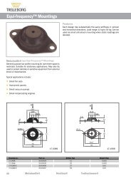
Suspension springFeaturesEach component is manufactured from high strength steelwith high impact and wear characteristics with heavy-duty <strong>to</strong>pand bot<strong>to</strong>m plates <strong>to</strong> resist negative loading and provide safeanchor points.ere is also a built in fail-safe device <strong>to</strong> prevent <strong>to</strong>tal mount failurein the case of severe overload. ese are also manufacturedfrom the highest-grade steel <strong>to</strong> provide high tensile strengthwithout compromising embrittlement.Trelleborg IAVS suspension springs are designed <strong>to</strong> provide amaintenance free flexible load bearing component allowingangular and shear movement whilst supporting high axialloads.e latest FE analysis technology has been applied <strong>to</strong> ensuremaximum reliability and minimum stress points whilst maintainingan uncomplicated design <strong>to</strong> minimize manufacturingcosts.Dimension (mm) Fail Safe Max. LoadPart no. A B C D d E F H t system kN10-01640-01 190 150 160 180 17 180 15 Bolt 15010-01641-01 190 150 160 180 17 182 15 Bolt 15010-01677-01 220 180 180 210 22 203 20 Bolt 40010-03501-01 170 140 140 165 14 55 18 150 9,5 Chain 5510-03132-01 190 150 160 184 16,5 185 10 N/A 7010-00951-01 190 150 160 184 16,5 80 25 185 10 Chain 7042Trelleborg Industrial AVS operates a policy of continuous improvement and development. We reserve the right <strong>to</strong> change design and specification of our products without prior notification or alteration of literature.We will not be held responsible for any danger or damage incurred through improper use or installation.
WasherTop and bot<strong>to</strong>m washersOverload and rebound washers (<strong>to</strong>p and bot<strong>to</strong>m) are necessary<strong>to</strong> limit maximum movement in the event of shock loading and<strong>to</strong> provide fail-safe connections for mobile applications.Type ASteel WasherType BTop Stepped Steel WasherType CRebound Washer with RubberØACØBØAØEDCØBØEØADCØBDimension in mmPart no. Type A B C D E Top Washer <strong>to</strong>: Bot<strong>to</strong>m Washer <strong>to</strong>:20-00531-01 A 50 10 4 17-0379, 17-1629, 17-1743 & MCR 27/1908 17-0379 & MCR 27/190820-00536-01 A 51 16 4 MCR 51/3216 17-1690, 17-1691 & MCR 51/321620-00416-01 A 52 12,5 3 17-1690, 17-1691, HK 60, EH 4850 & MCR 45/2810 EH 4850, HK 60 & MCR 45/281020-00644-01 A 55 20 5 HK 60020-01495-01 A 66 16,2 5 17-2190, MDS 66/4020, EH 6463 & MCR 64/3820 MDS 66/4020, EH 6463 & MCR 64/382011-1009, 11-1028, 17-0391, 17-0566, 17-0890, 11-1009, 11-1028, 17-0276, 17-0277, 17-0285,20-00532-01 A 80 16 5 17-1032, 17-1865, MCR 75/4624 & MDS 80/3820 17-0311, 17-0341, 17-0391, 17-0566, 17-0890,17-1032, 17-1865, MCR 75/4624 & MDS 80/382020-00003-01 A 80 20,5 8 11-1027 11-102720-00533-01 A 100 20 6 17-1101, 17-1650, 17-1843, EH 9075 & MCR 95/5119 17-1101,17-1650,17-1843, EH 9075 & MCR 95/511920-01494-01 A 100 17 7 17-2178 & 17-1997 17-199720-01493-01 A 124 22 9 17-1984 & 17-193120-00534-01 A 139 24 10 11-1029, 17-1550, 17-1814 17-1814 & 15-155020-00529-01 B 55 12 4 2 25 17-0189, 17-0241, 17-0248, 17-0472 & 17-047920-00528-01 B 80 20 5 2 35 17-0225 & 17-122720-00773-01 B 80 16 5 2 31 17-0276, 17-0277, 17-0285, 17-0311 & 17-034120-00643-01 B 110 20 5 3 52,5 HK 60020-00527-01 B 116 24 8 4 47 17-0146 & 17-016810-03724-01 C 47,5 10 3,2 3,15 24 17-1629 & 17-174310-00524-01 C 50 12 4 2 25 17-0189, 17-0241, 17-0248, 17-0472 & 17-047920-00036-01 C 75 20 6 3 50 17-0225 & 17-122720-00031-01 C 100 25 7 4 47 17-0146 & 17-0168Trelleborg Industrial AVS operates a policy of continuous improvement and development. We reserve the right <strong>to</strong> change design and specification of our products without prior notification or alteration of literature.We will not be held responsible for any danger or damage incurred through improper use or installation.43
A SAFECHOICEALL OVER THE WORLDS A L E ST E C H N I C A L C E N T E RP R O D U C T I O NHead OfficeTrelleborg Industrial AVS1 Hoods Close, LeicesterLE4 2BN, EnglandTel: +44 116 267 0300Fax: +44 116 267 0301industrialavs.uk@trelleborg.comBranchesTrelleborg Industrial AVS Belux(p/a) Trelleborg Wheel Systems Belgium NVBrugsesteenweg 7BE-9940 Evergem, BelgiumTel: +32 9 258 10 94Fax: +32 9 253 61 80industrialavs.belgium@trelleborg.comTrelleborg Industrial AVS Netherlands BVZeemanstraat 71-73NL-2991 XR Barendrecht, HollandTel: +31 10 292 7414Fax: +31 10 479 7079industrialavs.holland@trelleborg.comTrelleborg Industrial AVS France SASMini Parc du Verger, Bâtiment G1, rue de Terre NeuveFR-91940 Les Ulis, FranceTel: +33 1 64 86 42 60Fax: + 33 1 64 86 42 69industrialavs.france@trelleborg.comTrelleborg Industrial AVS SwedenP O Box 9020SE-15 109 Södertälje SwedenTel: +46 8 550 34 490Fax: +46 8 550 34 494industrialavs.sweden@trelleborg.comTrelleborg Industrial AVS SwedenSE-231 81 Trelleborg, SwedenTel: +46 410 510 00Fax: +46 410 193 70industrialavs.sweden@trelleborg.comTrelleborg Industrial AVS Germany GmbHDudenstrasse 27 - 35DE-68167 Mannheim, GermanyTel: +49 621 484 650Fax: +49 621 484 6565industrialavs.germany@trelleborg.comTrelleborg Industrial AVS USA, Inc.1431 East Algonquin Road,Arling<strong>to</strong>n Heights, Illinois 60005 USATel: +1 847-357 1600Fax: +1 847-357 1701industrialavs.usa@trelleborg.comTrelleborg Industrial AVS Italyc/o Trelleborg Wheel Systems SpaVia V. De Vizzi, 60I-20092 Cinisello Balsamo (MI), ItalyTel: +39 02 660 393 80Fax: +39 02 660 393 81industrialavs.italy@trelleborg.comwww.trellextreme.com