FlashPro430 User's Manual
FlashPro430 User's Manual
FlashPro430 User's Manual
- No tags were found...

Create successful ePaper yourself
Turn your PDF publications into a flip-book with our unique Google optimized e-Paper software.
<strong>FlashPro430</strong>USB-MSP430 Flash ProgrammerUser’s <strong>Manual</strong>Software version 4.3PM010A04 Rev.25July-29-2009
Elprotronic Inc.16 Crossroads DriveRichmond Hill,Ontario, L4E-5C9CANADAWeb site: www.elprotronic.comE-mail: info@elprotronic.comFax: 905-780-2414Voice: 905-780-5789Copyright © Elprotronic Inc. All rights reserved.Disclaimer:No part of this document may be reproduced without the prior written consent of Elprotronic Inc.The information in this document is subject to change without notice and does not represent acommitment on any part of Elprotronic Inc. While the information contained herein is assumed tobe accurate, Elprotronic Inc. assumes no responsibility for any errors or omissions.In no event shall Elprotronic Inc, its employees or authors of this document be liable for special,direct, indirect, or consequential damage, losses, costs, charges, claims, demands, claims for lostprofits, fees, or expenses of any nature or kind.The software described in this document is furnished under a licence and may only be used or copiedin accordance with the terms of such a licence.Disclaimer of warranties: You agree that Elprotronic Inc. has made no express warranties to Youregarding the software, hardware, firmware and related documentation. The software, hardware,firmware and related documentation being provided to You “AS IS” without warranty or supportof any kind. Elprotronic Inc. disclaims all warranties with regard to the software, express or implied,including, without limitation, any implied warranties of fitness for a particular purpose,merchantability, merchantable quality or noninfringement of third-party rights.Limit of liability: In no event will Elprotronic Inc. be liable to you for any loss of use, interruptionof business, or any direct, indirect, special incidental or consequential damages of any kind(including lost profits) regardless of the form of action whether in contract, tort (includingnegligence), strict product liability or otherwise, even if Elprotronic Inc. has been advised of thepossibility of such damages.2
END USER LICENSE AGREEMENTPLEASE READ THIS DOCUMENT CAREFULLY BEFORE USING THE SOFTWARE ANDTHE ASSOCIATED HARDWARE. ELPROTRONIC INC. AND/OR ITS SUBSIDIARIES(“ELPROTRONIC”) IS WILLING TO LICENSE THE SOFTWARE TO YOU AS ANINDIVIDUAL, THE COMPANY, OR LEGAL ENTITY THAT WILL BE USING THESOFTWARE (REFERENCED BELOW AS “YOU” OR “YOUR”) ONLY ON THE CONDITIONTHAT YOU AGREE TO ALL TERMS OF THIS LICENSE AGREEMENT. THIS IS A LEGALAND ENFORCABLE CONTRACT BETWEEN YOU AND ELPROTRONIC. BY OPENING THISPACKAGE, BREAKING THE SEAL, CLICKING “I AGREE” BUTTON OR OTHERWISEINDICATING ASSENT ELECTRONICALLY, OR LOADING THE SOFTWARE YOU AGREETO THE TERMS AND CONDITIONS OF THIS AGREEMENT. IF YOU DO NOT AGREE TOTHESE TERMS AND CONDITIONS, CLICK ON THE “I DO NOT AGREE” BUTTON OROTHERWISE INDICATE REFUSAL, MAKE NO FURTHER USE OF THE FULL PRODUCTAND RETURN IT WITH THE PROOF OF PURCHASE TO THE DEALER FROM WHOM ITWAS ACQUIRED WITHIN THIRTY (30) DAYS OF PURCHASE AND YOUR MONEY WILLBE REFUNDED.1. License.The software, firmware and related documentation (collectively the “Product”) is the property ofElprotronic or its licensors and is protected by copyright law. While Elprotronic continues to ownthe Product, You will have certain rights to use the Product after Your acceptance of this license.This license governs any releases, revisions, or enhancements to the Product that Elprotronic mayfurnish to You. Your rights and obligations with respect to the use of this Product are as follows:YOU MAY:A. use this Product on many computers;B. make one copy of the software for archival purposes, or copy the software onto the hard diskof Your computer and retain the original for archival purposes;C. use the software on a networkYOU MAY NOT:A. sublicense, reverse engineer, decompile, disassemble, modify, translate, make any attemptto discover the Source Code of the Product; or create derivative works from the Product;B. redistribute, in whole or in part, any part of the software component of this Product;C. use this software with a programming adapter (hardware) that is not a product ofElprotronic Inc.2. CopyrightAll rights, title, and copyrights in and to the Product and any copies of the Product are owned byElprotronic. The Product is protected by copyright laws and international treaty provisions.Therefore, you must treat the Product like any other copyrighted material.3
This device complies with Part 15 of the FCC Rules.Operation is subject to the following two conditions:(1) this device may not cause harmful interference and(2) this device must accept any interference received,including interference that may cause undesiredoperation.NOTE: Thisequipment has been tested and found to comply with the limits for a Class B digital devices, pursuant to Part 15of the FCC Rules. These limits are designed to provide reasonable protection against harmful interference in aresidential installation. This equipment generates, uses, and can radiate radio frequency energy and, if notinstalled and used in accordance with the instruction manual, may cause harmful interference to radiocommunications. However, there is no guarantee that interference will not occur in a particular installation. Ifthis equipment does cause harmful interference to radio or television reception, which can be determined byturning the equipment off and on, the user is encouraged to try to correct the interference by one of more of thefollowing measures:* Reorient or relocate the receiving antenna* Increase the separation between the equipment and receiver* Connect the equipment into an outlet on a circuit different from that to which the receiver is connected* Consult the dealer or an experienced radio/TV technician for help.Warning: Changes or modifications not expressly approved by Elprotronic Inc. could void the user’s authorityto operate the equipment.This Class B digital apparatus meets all requirements of the CanadianInterference-Causing Equipment Regulations.Cet appereil numerique de la classe B respecte toutes les exigences duReglement sur le material brouilleur du Canada.5
Table of Contents1. Introduction . . . . . . . . . . . . . . . . . . . . . . . . . . . . . . . . . . . . . . . . . . . . . . . . . . . . . . . . . . . . . 92. Features . . . . . . . . . . . . . . . . . . . . . . . . . . . . . . . . . . . . . . . . . . . . . . . . . . . . . . . . . . . . . . . 112.1 Customized features . . . . . . . . . . . . . . . . . . . . . . . . . . . . . . . . . . . . . . . . . . . 132.1.1 Encrypted Project option . . . . . . . . . . . . . . . . . . . . . . . . . . . . . . . . . . 132.1.2 Script file . . . . . . . . . . . . . . . . . . . . . . . . . . . . . . . . . . . . . . . . . . . . . . 132.1.3 DLLs . . . . . . . . . . . . . . . . . . . . . . . . . . . . . . . . . . . . . . . . . . . . . . . . . 132.1.4 Self Test Program . . . . . . . . . . . . . . . . . . . . . . . . . . . . . . . . . . . . . . . 133. Getting Started . . . . . . . . . . . . . . . . . . . . . . . . . . . . . . . . . . . . . . . . . . . . . . . . . . . . . . . . . . 143.1 Software Installation . . . . . . . . . . . . . . . . . . . . . . . . . . . . . . . . . . . . . . . . . . . 143.1.1 Driver Installation . . . . . . . . . . . . . . . . . . . . . . . . . . . . . . . . . . . . . . . 143.2 Hardware Setup . . . . . . . . . . . . . . . . . . . . . . . . . . . . . . . . . . . . . . . . . . . . . . . 183.3 Starting up “<strong>FlashPro430</strong>" Flash Programmer . . . . . . . . . . . . . . . . . . . . . . . 203.4 X-Pro430 Selector . . . . . . . . . . . . . . . . . . . . . . . . . . . . . . . . . . . . . . . . . . . . . 204. Programming Dialogue Screen . . . . . . . . . . . . . . . . . . . . . . . . . . . . . . . . . . . . . . . . . . . . . 224.1 Interface Type . . . . . . . . . . . . . . . . . . . . . . . . . . . . . . . . . . . . . . . . . . . . . . . . 234.2 Microcontroller Type . . . . . . . . . . . . . . . . . . . . . . . . . . . . . . . . . . . . . . . . . . . 244.4 Blow Security Fuse and Open Password File . . . . . . . . . . . . . . . . . . . . . . . . 304.5 Power Device from Adapter . . . . . . . . . . . . . . . . . . . . . . . . . . . . . . . . . . . . . 354.6 Device Action box . . . . . . . . . . . . . . . . . . . . . . . . . . . . . . . . . . . . . . . . . . . . . 364.6.1 Auto Program button . . . . . . . . . . . . . . . . . . . . . . . . . . . . . . . . . . . . . 384.6.2 Verify Security Fuse / Password button . . . . . . . . . . . . . . . . . . . . . . . 394.6.3 Erase Flash button . . . . . . . . . . . . . . . . . . . . . . . . . . . . . . . . . . . . . . . 394.6.4 Blank Check button . . . . . . . . . . . . . . . . . . . . . . . . . . . . . . . . . . . . . . 394.6.5 Write Flash button . . . . . . . . . . . . . . . . . . . . . . . . . . . . . . . . . . . . . . . 404.6.6 Verify Flash button . . . . . . . . . . . . . . . . . . . . . . . . . . . . . . . . . . . . . . 404.6.7 Read/ Copy Flash button . . . . . . . . . . . . . . . . . . . . . . . . . . . . . . . . . . 414.7 Next button . . . . . . . . . . . . . . . . . . . . . . . . . . . . . . . . . . . . . . . . . . . . . . . . . . 435. Data viewers . . . . . . . . . . . . . . . . . . . . . . . . . . . . . . . . . . . . . . . . . . . . . . . . . . . . . . . . . . . 446. Memory Option Dialogue Screen . . . . . . . . . . . . . . . . . . . . . . . . . . . . . . . . . . . . . . . . . . . 476.1 Memory Erase/Write/Verify Group . . . . . . . . . . . . . . . . . . . . . . . . . . . . . . . . 486.2 Retain Data in Flash . . . . . . . . . . . . . . . . . . . . . . . . . . . . . . . . . . . . . . . . . . . . 506.3 DCO constants verification . . . . . . . . . . . . . . . . . . . . . . . . . . . . . . . . . . . . . . 506.4 Read Group . . . . . . . . . . . . . . . . . . . . . . . . . . . . . . . . . . . . . . . . . . . . . . . . . . 516.5 Verification Group . . . . . . . . . . . . . . . . . . . . . . . . . . . . . . . . . . . . . . . . . . . . . 51<strong>FlashPro430</strong> - USB-MSP430 Flash ProgrammerPM010A04 Rev.256
7. Adapter Options . . . . . . . . . . . . . . . . . . . . . . . . . . . . . . . . . . . . . . . . . . . . . . . . . . . . . . . . . 537.1 JTAG / SBW / BSL Communication Speed Dialogue Box . . . . . . . . . . . . . . 537.1.1 BSL Communication Speed . . . . . . . . . . . . . . . . . . . . . . . . . . . . . . . . 537.1.2 JTAG Communication Speed . . . . . . . . . . . . . . . . . . . . . . . . . . . . . . 547.1.3 Spy-Bi-Wire Communication Speed . . . . . . . . . . . . . . . . . . . . . . . . . 547.2 Reset Dialogue Box . . . . . . . . . . . . . . . . . . . . . . . . . . . . . . . . . . . . . . . . . . . . 557.2.1 Reset pulse duration . . . . . . . . . . . . . . . . . . . . . . . . . . . . . . . . . . . . . . 567.2.2 Final Target Device action . . . . . . . . . . . . . . . . . . . . . . . . . . . . . . . . . 567.3 Preferences Dialogue Box . . . . . . . . . . . . . . . . . . . . . . . . . . . . . . . . . . . . . . . 578. Serialization . . . . . . . . . . . . . . . . . . . . . . . . . . . . . . . . . . . . . . . . . . . . . . . . . . . . . . . . . . . . 608.1 Introduction . . . . . . . . . . . . . . . . . . . . . . . . . . . . . . . . . . . . . . . . . . . . . . . . . . 608.2 Serialization Dialogue Screen . . . . . . . . . . . . . . . . . . . . . . . . . . . . . . . . . . . . 618.2.1 Serial number File . . . . . . . . . . . . . . . . . . . . . . . . . . . . . . . . . . . . . . . 628.2.2 Serial number formats . . . . . . . . . . . . . . . . . . . . . . . . . . . . . . . . . . . . 628.2.2.1 HEX ( MSB first, MSW first, LSW/LSB first ) formats . . . 638.2.2.2 BCD format . . . . . . . . . . . . . . . . . . . . . . . . . . . . . . . . . . . . . 668.2.2.3 ASCII format . . . . . . . . . . . . . . . . . . . . . . . . . . . . . . . . . . . . 698.2.3 Model, Group, Revision . . . . . . . . . . . . . . . . . . . . . . . . . . . . . . . . . . . 728.2.4 Device Serialization box . . . . . . . . . . . . . . . . . . . . . . . . . . . . . . . . . . 728.2.5 Bar Code Scanner setup . . . . . . . . . . . . . . . . . . . . . . . . . . . . . . . . . . . 738.3 Serialization Report Dialogue Screen . . . . . . . . . . . . . . . . . . . . . . . . . . . . . . 748.4 SN data file . . . . . . . . . . . . . . . . . . . . . . . . . . . . . . . . . . . . . . . . . . . . . . . . . . 759. Check Sum Options . . . . . . . . . . . . . . . . . . . . . . . . . . . . . . . . . . . . . . . . . . . . . . . . . . . . . . 799.1 Check Sum types . . . . . . . . . . . . . . . . . . . . . . . . . . . . . . . . . . . . . . . . . . . . . . 8210. BSL Password and Access . . . . . . . . . . . . . . . . . . . . . . . . . . . . . . . . . . . . . . . . . . . . . . . . 8711. DCO calibration . . . . . . . . . . . . . . . . . . . . . . . . . . . . . . . . . . . . . . . . . . . . . . . . . . . . . . . 8912. Script File - defined programming sequence . . . . . . . . . . . . . . . . . . . . . . . . . . . . . . . . . . 9112.1 Script button . . . . . . . . . . . . . . . . . . . . . . . . . . . . . . . . . . . . . . . . . . . . . . . . . 9112.2 Script file option . . . . . . . . . . . . . . . . . . . . . . . . . . . . . . . . . . . . . . . . . . . . . . 9312.3 Script commands . . . . . . . . . . . . . . . . . . . . . . . . . . . . . . . . . . . . . . . . . . . . . . 9313. Project and Configuration Load / Save . . . . . . . . . . . . . . . . . . . . . . . . . . . . . . . . . . . . . 10013.1 Load / Save Setup . . . . . . . . . . . . . . . . . . . . . . . . . . . . . . . . . . . . . . . . . . . . 10013.2 Load / Save Project . . . . . . . . . . . . . . . . . . . . . . . . . . . . . . . . . . . . . . . . . . . 10013.3 Commands combined with the executable file . . . . . . . . . . . . . . . . . . . . . . 10414. Adapter description . . . . . . . . . . . . . . . . . . . . . . . . . . . . . . . . . . . . . . . . . . . . . . . . . . . . 10815. Target connection . . . . . . . . . . . . . . . . . . . . . . . . . . . . . . . . . . . . . . . . . . . . . . . . . . . . . 111<strong>FlashPro430</strong> - USB-MSP430 Flash ProgrammerPM010A04 Rev.257
Appendix A - Specification . . . . . . . . . . . . . . . . . . . . . . . . . . . . . . . . . . . . . . . . . . . . . . . 119Appendix B - MSP430.dll for IDE debugging software . . . . . . . . . . . . . . . . . . . . . . . . . 121- Setup with IAR EW430 Embedded Workbench . . . . . . . . . . . . . . . . . . . . . . . . . 123- Setup with TI Code Composer Essentials . . . . . . . . . . . . . . . . . . . . . . . . . . . . . . 126- Setup with Rowley CrossStudio for MSP430 . . . . . . . . . . . . . . . . . . . . . . . . . . . . 128Appendix C - Self Test Program . . . . . . . . . . . . . . . . . . . . . . . . . . . . . . . . . . . . . . . . . . 133<strong>FlashPro430</strong> - USB-MSP430 Flash ProgrammerPM010A04 Rev.258
1. Introduction<strong>FlashPro430</strong> (model USB-MSP430-FPA) programmer is dedicated to program the TexasInstruments MSP430Fxx family microcontrollers. Using <strong>FlashPro430</strong> programmer the targetdevice can be programmed via the JTAG Interface (4-wires), SBW (Spy-Bi-Wire) (2-wires) or viathe BSL (Boot Strap Loader) Interface. MSP430Fxx microcontrollers can be program via the JTAGor Spy-Bi-Wire Interface as long, as the Security Fuse is not blown. When the Security Fuse is blownthen the MSP430Fxx microcontrollers still can be accessible, but only via the BSL Interface.Each programmer package(Figure 1-1) consist of a microcontrollerbased adapter, Windows TM basedsoftware and cable to connect theadapter with the computer’s USB port.The internal adapter software allows tocommunicate with the programmeddevice with the high speed. Theprogramming speed using the JTAGinterface is around 29 kbytes/s. TheFast BSL Interface allows tocommunicate with the programmeddevice at speed of up to 350 kbits/s,Figure 1-1which is over 35 times faster than withstandard BSL (communication speed9.6 kb/s). Due to this high speed communication, programming time is very short and programmercan be used to program flash devices in the production process. For example, a microcontroller with60 kB Flash, such as MSP430F149, can be programmed in 3.5 seconds via the JTAG Interface, orin 6 seconds via the BSL Interface. This time includes initialization, erasing memory, blankchecking, programming and fast verification.To facilitate high speed communication via the BSL Interface, a new Fast Bootstrap Loader(Fast BSL) is temporarily downloaded to the RAM of each programmed device. Due to the smallsize of Fast BSL, almost all TI microcontrollers from MSP430Fxx family can utilize high speedcommunication. Microcontrollers with small RAM (128 bytes - only 3 family members) can beprogrammed with the standard communication speed (9.6 kb/s - communication speed is selectedautomatically). Programming time for these types of microcontrollers is not very long, since the sizeof the programming FLASH is very small (up to 2 kB).<strong>FlashPro430</strong> - USB-MSP430 Flash ProgrammerPM010A04 Rev.259
To simplify production process the programming software package can assign serialsnumber, model type, and revision. Each serial number is unique for each programmed device andis assigned automatically. Several serial number formats are available.There are a number of erase/write options also available. This allows to erase/write all flashmemory, or just the specified fragment of memory. This feature is very useful when only part ofprogrammed data/code should be replaced. For example this feature can be used to download theserial number, calibration data or personality data without losing existing program code.Currently (Dec-2006) four types of the USB Flash Programming Adapters are supported bythe <strong>FlashPro430</strong> software (from Elprotronic):1. <strong>FlashPro430</strong> FPA (obsolete) ( model PN: USB-MSP430-FPA-1.x )2. <strong>FlashPro430</strong> FPA (obsolete) ( model PN: USB-MSP430-FPA-2.x )3. <strong>FlashPro430</strong> FPA (RoHS) ( model PN: USB-FPA-4.x )4. GangPro430 FPA ( model PN: USB-MSP430-FPA-3.x )5. GangPro430 FPA (RoHS) ( model PN: USB-FPA-5.x )All FPA models can be used with the <strong>FlashPro430</strong> programming software that allows to programonly one target device at the time with some different performance - see table below.FPA -> USB-MSP430-FPA-1.x USB-MSP430-FPA-2.0and USB-FPA-4.xUSB-MSP430-FPA-3.0USB-FPA-5.x(GangPro430 FPA)1. Vcc from FPA2. External Vcc3. JTAG interfacespeed 4 Mb/sspeed 1 Mb/sspeed 400 kb/s4. Spy-Bi-Wire interface5. BSL Interface6. MSP430.dll for debugging3.2 V1.8 to 3.6VYESYESYESYESYES **YESYES2.2 to 3.6V step 0.2V1.8 to 3.6VYESYESYESYESYESYESYES2.2 to 3.6V step 0.2V1.8 to 3.6VYESNOYESYESYESNOYESNote ** :In the old adapters - USB-MSP430-FPA-1.0, 1.1 and 1.2 the blow security fuse isnot supported when the Spy-Bi-Wire is used. See chapter 13 for details.All other performance not listed in the table above are the same when used with the <strong>FlashPro430</strong>programming software. Note, that the GangPro430 FPA (USB-MSP430-FPA-3.0 or USB-FPA-5.x)can also be used with the GangPro430 software to access few target device from one FPA adapter.<strong>FlashPro430</strong> - USB-MSP430 Flash ProgrammerPM010A04 Rev.2510
2. Features<strong>FlashPro430</strong> programmer is dedicated to program the Texas Instruments MSP430Fxxmicrocontroller family via JTAG, Spy-Bi-Wire or BSL interface.When the JTAG or Spy-Bi-Wire Interface is used, then the <strong>FlashPro430</strong> programmer isusing the standard JTAG/SBW communication port, available on all MSP430 microcontroller.Detailed information describing features of the JTAG communication port can be found in the TexasInstruments ( TI ) documentation - SLAA149 -“Programming a Flash-Based MSP430 Using theJTAG Interface”.To facilitate high speed communication via the JTAG / Spy-Bi-Wire interface, an applicationsoftware for the programming adapter has been optimized for the maximum speed. Also a few newprocedures have been implemented, decreasing the flash programming time. Key features of the<strong>FlashPro430</strong> programmer using JTAG/SBW communication port are as follows:- support all MSP430 flash-based devices,- programming speed approximately 29 kB/s (via JTAG interface),- mass erase, erase main memory only or segment erase,- fast verify and blank check,- check sum calculation,- supports programming of the JTAG access security fuse (permanently disables devicememory access via JTAG/SBW),When the BSL Interface is used, then the <strong>FlashPro430</strong> programmer is using the standardBSL communication port, available on all MSP430 microcontrollers. Detailed informationdescribing features of the standard BSL can be found in the Texas Instruments ( TI ) documentation- SLAA089A -“Features of the MSP430 Bootstrap Loader”.To facilitate high speed communication a new Fast Bootstrap Loader (Fast BSL) (proprietaryof Elprotronic Inc.) is temporary downloaded to the RAM of each programmed device. The Fast BSLprovides the following functions:- mass erase, erase main memory only or segment erase,- blank memory check,- check sum calculation,- write and verify word (2 bytes) into flash memory,- read word (2 bytes) from memory.<strong>FlashPro430</strong> - USB-MSP430 Flash ProgrammerPM010A04 Rev.2511
Major features of the <strong>FlashPro430</strong> programmer are:* Support all MSP430Fxx microcontrollers from TI.* Our programmers are professionally made and are recommended by Texas Instrumentsas the Third Party Tools source.* Our programmers are currently the fastest programmers on the market.* Programmer has a unique feature - three interfaces in one package allowing to program thetarget device via JTAG, Spy-Bi-Wire or BSL Interface.* To speed up production process optimized programming algorithms are used to significantlyreduce programming time. Our proprietary Fast BSL algorithms allow to communicate withthe target devices over 35 times faster then standard TI BSL (9.6kb/s) reducingprogramming time from few minutes to few seconds.* Programming speed via JTAG Interface is around 29 kbytes/s.* Blow the JTAG security fuse capability.* No code size limitations.* Full memory or sector memory erase capability.* Write Check Sum verification.* DCO calibration via JTAG, Spy-Bi-Wire and BSL* Target device can be powered from the programming adapter or from external source.* Easy to use Windows TM based software.* Programmer accept TI (*.txt), Motorola (*.s19) and Intel (*.hex) data files for programming.* Combine code files capability.* Lock setup capability, useful in production.* Software package can assign and automatically increment serial number, model type andrevision. Serial Number with or without an automatically inserted current date can be storedin the FLASH memory in HEX, BCD or ASCII format. Log file capability allowing toreview information about the flashed target devices.* DLL software package can control programmer from other programs.* Programmer has been fully tested to comply with the FCC and CE requirements.* Our programmers are inexpensive - for users interested in basic features we providelimited, or lite software version.* Using USB-1.1 (12Mbits/s) Port to communicate with the Programming Adapter.* Communication with the target device via JTAG/SBW/BSL Interface using TI-standard14-pins header connector.<strong>FlashPro430</strong> - USB-MSP430 Flash ProgrammerPM010A04 Rev.2512
2.1 Customized features<strong>FlashPro430</strong> programmer can be controlled from external software or programmingsequences can be customized. These features are very useful in production environment. Standardprogramming software <strong>FlashPro430</strong> has a lot of options described above, but of course it can notcover all customer’s requirements.2.1.1 Encrypted Project optionContents of the project that include code contents downloaded to target device can beencrypted and blocked against unauthorised access.2.1.2 Script fileTo extend programming features programming software supports user defined programmingsequences saved in the script file. That easy method can be created by any user without knowingprogramming languages and techniques. Programming sequence up to 1000 lines can be created. Alllines contains sequence of the pressed buttons with extra few condition options. This programmingmethod is described in chapter 10 on this manual. Script file option is not available in lite softwareversion.2.1.3 DLLsWhen the customized programming sequence is not covering customer’s requirements, thenan attached to software package DLLs can be used. DLLs allows to fully control programmingadapter from external software written in MS Visual C++, MS Visual Basic, LABView, DOS orother programming packages like Borland C++ etc. See “Fast MSP430 Flash Programmer -Remote Control Programming User’s Guide” for details.2.1.4 Self Test ProgramSoftware package contains the Self Test program, that allows to check the adapter, targetdevice and connection functionality. The Self Test program uses the API-DLL for communicationbetween Self Test Program and hardware. See Appendix B in this manual for details.<strong>FlashPro430</strong> - USB-MSP430 Flash ProgrammerPM010A04 Rev.2513
3. Getting StartedThe X-Pro430 programmer package contains:1. One READ ME FIRST document.2. One X-Pro430 Flash Programmer CD ROM ( Software + <strong>Manual</strong> ).3. One <strong>FlashPro430</strong>, ChainPro430 or GangPro430 (USB MSP430 FPA) FlashProgramming Adapter.4. One 6 feets length USB-A to USB-B cable extender.3.1 Software InstallationThe X-Pro430 USB MSP430 Flash Programming Software runs on PC under Windows TM ME,WinNT, 2000 or XP. Follow instructions below to install the software:1. Insert X-Pro430 (the USB MSP430 Flash Programming) Software CD into your CD-ROMdrive.2. The X-Pro430 Setup wizard appears automatically. Click Install X-Pro430 Programmer tobegin the installation process.3. If the Setup wizard does not start automatically, click the Start button and choose the Rundialogue box. Type “D:\SETUP.EXE”, where D represents the drive letter of your CD-ROMdrive. Then click the OK button.4. Once the installation program starts, on-screen instructions will guide you through theremainder of the installation. You must accept licence agreement before using software.3.1.1 Driver InstallationSoftware installation program is placing the USB driver files in the windows directoriesWindows\inf and Windows\system32\drivers that simplified driver installation.1. Plug in USB-MSP430-FPA to the PC USB Port, using provided cable extender (USB-A toUSB-B).==== Windows XP, VISTA ====2. The “New hardware has been found” - USB-FPA-BOOT should be displayed.<strong>FlashPro430</strong> - USB-MSP430 Flash ProgrammerPM010A04 Rev.2514
Figure 3.1-1Follow the wizard instruction to install the drivers.1. In the first Wizard dialogue screen (see Figure 3.1-1) select the “Yes, this timeonly” option.2. In the second Wizard dialogue screen (see Figure 3.1-2) select the “Instal thesoftware automatically (Recommend)” and press NEXT button.Figure 3.1-2<strong>FlashPro430</strong> - USB-MSP430 Flash ProgrammerPM010A04 Rev.2515
3. Software will search the driver for the USB-FPA-BOOT. It can take one minute tofind it. When the driver is found then the following warning will be displayed (Figure3.1-3)Figure 3.1.34. Ignore this message and press button “Continue Anyway”. The first USB-FPA-BOOT driver should be installed and following message displayed (Figure 3.1-4).<strong>FlashPro430</strong> - USB-MSP430 Flash ProgrammerPM010A04 Rev.2516
Figure 3.1-45. Press “Finish” button.After a few seconds the second new hardware will be found - the USB-FPA (Elprotronic).Repeat the procedures 1,2,3,4,5 as above and on the end the second driver for the USB-FPA(Elprotronic) will be installed (see Figure 3.1-5).Figure 3.1-5<strong>FlashPro430</strong> - USB-MSP430 Flash ProgrammerPM010A04 Rev.2517
If from any reason the wizard cannot find the USB drivers location then repeat steps 2,3,4using manual option and browse drivers from location software directoryC:\Program Files\Elprotronic\XPro USB Drivers\W2000,ME,XP==== Windows - 2000, 98-SE ====2. The “New hardware has been found” should be displayed. Follow the wizard instructionto install the drivers.3. Press ‘Next’ when the Device Wizard Driver screen appear.4. Select the following option on the wizard screen:* select for a suitable driver for my device (recommended)”and press ‘Next’.5. Select the third option - “Specify a location” for a location of the Driver Files.6. From the browser select the “D:\drivers\W2000,ME,XP” for Win-2000 or“D:\drivers\W98” for Win-98SE directory, where D:CD-ROM drive location or in theapplication software directoryC:\Program Files\Elprotronic\XPro USB Drivers\W98 and press ‘Next’.7. Driver installation process will start.Driver installation procedures should be done twice. Software will install two USB drivers - the Bootdriver and the Application driver. Reboot computer on the end.3.2 Hardware Setup<strong>FlashPro430</strong> software supports two adapter types - <strong>FlashPro430</strong> (USB-MSP430-FPAversions 1.0, 1.1, 1.2 and 2.0, USB-FPA 4.0, 4.1, 4.2 and 4.3) and GangPro430 (USB-MSP430-FPA-3.0 and USB-FPA-5.0) (see figure 3.2-1). When the GangPro430 adapter is detected by the<strong>FlashPro430</strong> software then the only lines used by the first target device are activated in the FPAadapter. Lines TDI/TDO-2 to TDI/TDO-6 becomes tri-stated.The <strong>FlashPro430</strong> adapters supports all interfaces1. JTAG (4Mb/s, 1Mb/s and 400 kb/s),2. Spy-Bi-Wire (fast and slow),(Note: The FPA - 1.0, 1.1 and 1.2 supports the Spy-Bi-Wire without fuse blown only)3. Fast BSL (350 kb/s and 90 kb/s) and BSL (9.6 kb/s),<strong>FlashPro430</strong> - USB-MSP430 Flash ProgrammerPM010A04 Rev.2518
while GangPro430 adapters supports only JTAG and BSL intefaces when the <strong>FlashPro430</strong> softwareis used.1. JTAG (1Mb/s and 400 kb/s),2. Spy-Bi-Wire (fast and slow),Figure 3.2-1 show available connection with target device using <strong>FlashPro430</strong> or GangPro430adapters.Figure 3.2-11. Connect USB-MSP430 Flash Programming Adapter to the PC USB Port, using providedcable extender (USB-A to USB-B).<strong>FlashPro430</strong> - USB-MSP430 Flash ProgrammerPM010A04 Rev.2519
2. Plug in socket connector from the USB-MSP430 Flash Programming Adapter to headerconnector on your device board. Make sure that pin 1 on your device board’s header isconnected to pin 1 of the socket connector. Pin 1 is marked as a red cable on the ribboncable.3.3 Starting up “<strong>FlashPro430</strong>" Flash ProgrammerTo start the <strong>FlashPro430</strong> Flash Programmer click on the Elprotronic <strong>FlashPro430</strong> icon.Figure 3.3-1Once started the software will attempt to access the programming adapter. If no error messagesappear then the software has initialized without a problem and you may begin using it. However, ifthe programming adapter is not detected an error message will appear. To correct the problem, makesure that the connection cable is properly attached and the USB driver is installed.3.4 X-Pro430 SelectorThe X-Pro430 ( <strong>FlashPro430</strong> (Single), ChainPro430 (Chain) or GangPro430 (Gang)) FlashProgramming Adapter (FPA) has Multi-USB feature. Up to 8 Flash Programming Adapters canbe connected to one PC. Each adapter can be controlled by one opened software application. Up toeight application software can be opened at the same time. Each application software can haveindependent setup from the other application software setup (code file, controlled microcontrollertype etc.)<strong>FlashPro430</strong> - USB-MSP430 Flash ProgrammerPM010A04 Rev.2520
Figure 3.4-1When more then one X-Pro430 adapter is connected to PC then following X-Pro430 selectordialogue screen will be displayed on the PC screen (see Figure 3.4-1). Using available buttons theone desired Flash Programming Adapter should be selected. Make a sure, that selected X-Pro430programming adapter is not used by other opened application.Selected X-Pro430’s serial number will be displayed on the left bottom side of the programmingdialogue screen. The <strong>FlashPro430</strong> programming software supports all X-Pro430 programmingadapters. <strong>FlashPro430</strong> programming software can be used to access a single target device,regardless type of the used FPA. Using the <strong>FlashPro430</strong> FPA (models USB-MSP430-FPA-1.x,USB-MSP430-FPA-2.0 or USB-FPA-4.x) the target device can be connected to FPA viaJTAG/SBW or BSL interface, while using the GangPro430 FPA (model USB-MSP430-FPA-3.0or USB-FPA-5.x) the target device can be accessible via JTAG/SBW interface only.<strong>FlashPro430</strong> - USB-MSP430 Flash ProgrammerPM010A04 Rev.2521
4. Programming Dialogue ScreenFigure 4-1. Programming dialogue box screen.The programming dialogue box (see Fig. 4-1.) contains a pull down menu, interface selectionbox, blow fuse box, device action buttons, report (status) window, open file buttons, processorinformation box, serial number box, power DC status and check sum result boxes.<strong>FlashPro430</strong> - USB-MSP430 Flash ProgrammerPM010A04 Rev.2522
All device action buttons, power ON/OFF button and the check sum result box have theirown status indicators. Each indicator can assume any of the following conditions:- blank - idle status.- yellow - Test in progress. For power on/off - DC voltage is correct.- green - access enabled.- red sign - access denied. For power on/off - DC voltage is too low (below 2.6V)- device action has been finished successfully.- device action has been finished, but result failed.- applies to blank check only - Memory is not clean, but the specified memory segment is.4.1 Interface TypeThe communication interface type - JTAG, Spy-Bi-Wire (SBW), BSL or Auto can beselected in the Interface group. When the programming adapter has implemented all types ofcommunication interface, then all buttons in the interface group are active, otherwise only oneselecting button is active - JTAG/Spy-Bi-Wire or BSL. Proper communication interface should beselected, otherwise communication with the target device can fail.Figure 4.1It is recommended to prepare in the target device board one 14-pin JTAG connector withJTAG/SBW and BSL connections (see chapter 11 for details). When the JTAG/SBW and BSLcommunication interfaces are connected between the target device and programming adapter, thenselection of any interface type can activate communication between the programming adapter anda target device.It is recommended to use by default communication through the JTAG Interface, becausethis communication is around two times faster than the communication through the BSL Interface.Also ‘blow the security fuse’ procedure is accessible only from the JTAG/SBW communicationport. When the security fuse is blown, then JTAG/SBW interfaces are unusable, and only the BSL<strong>FlashPro430</strong> - USB-MSP430 Flash ProgrammerPM010A04 Rev.2523
communication port can be used. When option Auto is selected, then communication always startingusing the JTAG interface. If blow of the security fuse has been detected, then communication iscontinuing using the BSL interfaces. Next communication is starting using the JTAG interface asthe first again.Note: Auto option can use only JTAG or BSL interface.4.2 Microcontroller TypeThe microcontroller type can be selected from the pull down fieldof the processor type group. The pull down field contains a list of allmicrocontrollers in MSP430Fxx family currently available.When communication between microcontroller and programmingadapter is initialized, the software will detect the target microcontroller’sautomatically. The type of detected microcontroller is displayed in thefield ‘Target:’. This allows the software to warn you if the connectedmicrocontroller does not match the one specified by the user.When communication between microcontroller and programmingadapter is using BSL Interface, then Bootstrap Loader (BSL) versiondownloaded from the target device is displayed in the field ‘BSL:’Texas Instruments has been created number of microcontroller’sgroups and numbers of the microcontroller’s type. Microcontrollers withthe same group has the same ID number saved in the ROM at thelocation 0x0FF0. Microcontrollers with the same group ID has a similarfeatures with a different size of RAM and FLASH.Contents of the ROM at location 0x0FF0 containing ID number Figure 4.2-1can be read using JTAG/SBW or BSL communication. Particular typeof the microcontroller in the same group ID can be detected when communication via JTAG/SBWis available, but this feature is not available via BSL interface communication. For programmingflash feature knowledge of the type of the microcontrollers is not required al long as size of FLASHis available.<strong>FlashPro430</strong> - USB-MSP430 Flash ProgrammerPM010A04 Rev.2524
In the example the four groups of microcontrollers are shown below. Tables containsfollowing information:- in [F112] - ID (in HEX format) taken from the ROM at location 0x0FF0,- F11x(1) - information displayed in the microcontroller type window in programmer dialogue box,- list of available microcontrollers in particular group with RAM and Flash size specification.[ F112 ] F11x(1)Name RAM size [bytes] ROM size [kbytes]MSP430F110MSP430F1101MSP430F1101AMSP430F1111AMSP430F112MSP430F1121MSP430F1121A1281281281282562562561 k1 k1 k2 k4 k4 k4 k[ 1132 ] F11x2Name RAM size [bytes] ROM size [kbytes]MSP430F1122MSP430F11322562564 k8 k[ F123 ] F122..F123Name RAM size [bytes] ROM size [kbytes]MSP430F122MSP430F1232562564 k8 k[ F149 ] F13x..F14xName RAM size [bytes] ROM size [kbytes]MSP430F133MSP430F135MSP430F147MSP430F1471MSP430F148MSP430F1481MSP430F149MSP430F14912565121024102420482048204820488 k16 k32 k32 k48 k48 k60 k60 k<strong>FlashPro430</strong> - USB-MSP430 Flash ProgrammerPM010A04 Rev.2525
When ‘Any’ microcontroller type is selected then only name of the microcontroller’s grouplike F13x..F14x is displayed in the Target microcontroller type. Because type of microcontrollercan not be fully detected (especially via BSL Interface) then the max. FLASH from the particulargroup is assigned, eg. 60kB for the group F13x..F14x (see table above). If the correct size of theFLASH is required then the desired microcontroller type should be selected. When communicationwith the target device is established and when the selected and the target microcontrollers are fromthe same group, then a size of the target device are taken from the selected microcontroller type datatable. In this case the full name of the microcontroller’s is displayed in the Target microcontrollertype field like MSP430F149 instead the group name F13x..F14x only. Otherwise themicrocontroller with the maximum size of FLASH from the detected group is selected (shown inbold in the tables above) and group name is displayed like F13x..F14x.<strong>FlashPro430</strong> - USB-MSP430 Flash ProgrammerPM010A04 Rev.2526
4.3 Code File Management<strong>FlashPro430</strong> flash programmer provides a few options to manage code files. These optionsallow the user to open a code file, combine several code files into a single file, and save theprogramming data into a code file. Following code formats are supplied - Texas Instruments *.txt,TI’s Code Composer Essentials *.out, Intel *.hex, Motorola *.s19, *.s28, *.s37, IAR UBROF-9*.d43 and IAR debug (Intel or Motorola) *.a43 formats. When the TI’s CCE file is used then thepath for the TI’s hex430.exe file should be specified. See Preferences dialog for details.Figure 4.3-1The Open Code File button, or the Open Code File from the FILE pull down menu, promptsfor opening the object file that contains the code data, as shown in Figure 4.3-1. When the file isselected the contents of the object file are downloaded into the PC memory. If the selectedmicrocontroller does not have enough memory to fit the data contained in the code file, the warningmessage in Figure 4.3-2 will be displayed.<strong>FlashPro430</strong> - USB-MSP430 Flash ProgrammerPM010A04 Rev.2527
Figure 4.3-2When code file is open and read successfully the code file name and full path will bedisplayed on the right side of the Open Code File button (see Fig.4-1 Programming dialogue boxscreen). Check sum calculated from the code file will be displayed in the “Check sum - Source”window. Contents of the selected file can be viewed by the selecting of ‘Code File Data’ from the‘View’ menu (see chapter 5).The Combine Code Files option allows up to 40 code files to be loaded into the PC memory.When this option is selected the programmer will create a new data block, which will contain thecombined data of the user selected files. In order to add a code file to the newly created data block,the user needs to press the ADD Code File button. The programmer will then prompt the user toFigure 4.3-3<strong>FlashPro430</strong> - USB-MSP430 Flash ProgrammerPM010A04 Rev.2528
4.4 Blow Security Fuse and Open Password FileThe microcontroller’s memory is protected against unauthorized access. When themicrocontroller is accessed via the JTAG/SBW interface, then the Security Fuse if blown isprotecting access to the microcontroller. Blowing the Security Fuse is not reversible and when done,then the JTAG/SBW interface becomes unusable.When JTAG/SBW interface is selected, then ‘Verify Security Fuse’ button allows toverification, if the fuse is blown or not. Fuse is verified also at the beginning of any device actioncommand.To blow the Security Fuse the check mark ‘Enable’ must be selected first (see Figure 4.4-1).Figure 4.4-1Because blowing of the Security Fuse is not reversible, the following warning message is displayedwhen check mark is selected to be enabled.Figure 4.4-2Note:If the option of blowing the Security Fuse is enabled, then if AUTO PROGRAM device actionis selected, the fuse will be blown without warning.<strong>FlashPro430</strong> - USB-MSP430 Flash ProgrammerPM010A04 Rev.2530
When ‘BLOW FUSE’ button is pressed, then two following warnings are displayed, before fuse willbe blown.Figure 4.4-3Figure 4.4-4When the button ‘YES’ is pressed twice, the procedure of blowing the security fuse will be initiated.When Security Fuse is blown, the JTAG/SBW interface becomes inoperable.TI prepared the second access to the MSP430 microcontroller via the BSL interface. Thisaccess is available any time, even if the Security Fuse is blown. To access the microcontroller viathe BSL interface a valid password must be provided. The password consists of 32 bytes of code atlocation 0xFFE0-0xFFFF for the F1xx, F2xx andF4xx, and 16 bytes of code at location 0xFFF0-0xFFFF for the F5xx MCU. If the correct password is not provided, access to the microcontrollervia BSL is limited to two commands - erase all memory and verify password. All other commandsare unavailable. When password is not known, then the all memory can be erased and a newpassword (all 0xFF) can unlock access to all BSL commands.<strong>FlashPro430</strong> - USB-MSP430 Flash ProgrammerPM010A04 Rev.2531
The software supports three types of passwords. The first password, or default, is used whenthe flash memory is blank, ie. all bytes contain value 0xFF. Consequently, the password contains 32bytes of 0xFF.The second password is provided by using the Open Password File button, or OpenPassword File from the FILE menu. This command opens the code file and retrieves 32 bytes ofdata that contain the password. Using this password allows the code in the flash memory to bemodified.The third password comes from the code file itself. Whenever Open Code File command isselected, data from the code file at the memory location 0xFFE0...0xFFFF is extracted for thisFigure 4.4-5purpose. The password obtained this way enables verification of memory contents.<strong>FlashPro430</strong> - USB-MSP430 Flash ProgrammerPM010A04 Rev.2532
The use of a password file is optional. If a password file is not used, then the remaining twopasswords will be used. All three passwords can be viewed by selecting View\Device Passwordsselected from main menu (see Fig.4.4-5).The three passwords are checked in sequence: from password file, from code file and defaultat the end. The first valid password will be accepted. If all passwords fail the following errormessage will appear:Figure 4.4-6When the F2xx or F4xx with BSL firmware version2.0 and higher are used then by defaultthe firmware allows to verify the BSL password only once. If the BSL password is wrong then thewhole contents of flash memory, including protected Info-A segment (with DCO calibration data)could be erased. When that kind of microcontroller is selected then the following dialog screen(Figure 4.4-7) is displayed that allows to select desired BSL password to be used first.<strong>FlashPro430</strong> - USB-MSP430 Flash ProgrammerPM010A04 Rev.2533
Figure 4.4-7If the first password failed to unlock the device then the default passwords will be used tounlock the device. If that happened, then of course some application cannot use the MSP if theapplication is using the DCO calibration content saved in the Info-A segment. The DCO calibrationdata should be restored first. If the DCO calibration data are erased then the <strong>FlashPro430</strong> softwarecan recalibrate the DCO constants using access via JTAG, Spy-Bi-Wire or Fast BSL. No extrahardware is required. The DCO are calibrated with tolerance +/- 1% for desired frequency and theDCO constants are saved in the flash memory. See chapter 6 for details how to make the setup forthe DCO recalibration.The BSL firmware version 2.0 and higher allows to disable the feature that the memory iserased when the password is incorrect and retry the BSL password again. If this option is used thenthe Info-A segment will not be erased and the DCO constants would be saved. See the BSLPassword and Access - chapter 9 for details.In the F5xx MCU the new BSL firmware is implemented with shorter password (16 bytesonly) and with fixed option that allows to try the password only once. If password is wrong then the<strong>FlashPro430</strong> - USB-MSP430 Flash ProgrammerPM010A04 Rev.2534
whole flash memory is erased including protected Info segments. It should be noticed that in theF5xx all calibration data are not located in the regular flash location (info or main memory segments)and all calibration data will not be erased.4.5 Power Device from AdapterThe programming adapter is powered from theUSB Port interface. Target device will be powered fromthe adapter, if check box ‘Enable’ in the ‘Power Devicefrom Adapter’ group (figure 4.5-1) is selected. When the‘Enable’ checkbox is selected a warning message shownin figure 4.5-2 will be displayed. If you confirm thisselection by clicking YES, then POWER ON/OFFbutton is enabled. By clicking POWER ON/OFF buttonFigure 4.5-1you can turn the power on or off on the target device.Current DC voltage on the target device is permanently monitored and displayed in the ‘DeviceVoltage’ field in the ‘Power Device from Adapter’ group, even if the target device is powered fromthe external DC sources. If DC voltage is higher then 2.7 V, then yellow box will be displayed,indicating that DC voltage is OK and target device is fully functional under this DC voltage. If DClevel is below 2.7V, but higher then 1V, then access denied sign box will be displayed (red sign withwhite line). If DC level is below 1V, then blank sign box will be displayed.Figure 4.5-2<strong>FlashPro430</strong> - USB-MSP430 Flash ProgrammerPM010A04 Rev.2535
Note:Programming adapter prevents any program from running on the target device, whenprogramming adapter is connected to target device via BSL connector.When the target device is powered from its own power supply or battery then the check box ‘Enable’should not be selected.RESET button located under POWER ON/OFF button can generate reset pulse to the targetdevice. Pressing this button the target devices can be reset manually at any time, starting the target’sdevice application program from the beginning.4.6 Device Action boxDevice Action box contains 9 buttons (see Figure 4.6-1 and 4.6-2) and 9 status boxes. Eachbutton allows a specific action to be executed. Software procedures related to each action allow youto fully execute the desired task, without the need to follow a specific sequence of actions. Everyaction starts by powering up the target device, if Power Device from the Adapter is enabled. Whenthe DC voltage level becomes higher then 2.7V, the communication with the target device is initiatedvia JTAG/SBW or BSL Interface. When the JTAG/SBW Interface is selected then the security fuseFigure 4.6-1JTAG/SBW InterfaceselectedFigure 4.6-2BSL Interfaceselected.<strong>FlashPro430</strong> - USB-MSP430 Flash ProgrammerPM010A04 Rev.2536
is verified, if access to the microcontroller is available. When the BSL Interface is selected, then thepassword is verified to unlock access to the microcontroller and the Fast BSL is downloaded to thetarget device. Once the specified action is completed successfully the green check mark will appear.Also, the device will return to the state it was in before the action was executed.Progress of all actions is displayed in the report window. If the particular action has beenfinished successfully, then message ‘done’ or ‘OK’ will appear on the right side of processedprocedure (Fig.4.6.3). If not, a message ‘failed’ will be displayed and selected action will beterminated. Final status is also displayed in the Status window (see Fig.4.6-4) as Active (blue), Pass(green), or Fail (red). On the bottom of the programmer dialogue screen the progress bar is displayedand the total run time is shown in the report window. Run time does not include the time when userinteraction is required.Figure 4.6-3<strong>FlashPro430</strong> - USB-MSP430 Flash ProgrammerPM010A04 Rev.2537
4.6.1 Auto Program buttonAuto Program button is the most frequently used button when programming microcontrollersin the production process. Auto Program button activates all required procedures to fully programand verify the flash memory contents. Typically, when flash memory needs to be erased, AutoProgram executes the following procedures:- reload code file when “Reload Code File” is selected(useful for debugging when the code file is frequently modified)- initialization- read labelling information (Serial Number, Model, Group, Revision) (optional)- calculate defined Check Sum (or CRC) if selected,- erase flash memory,- confirm if memory has been erase,- flash programming and verification,- labelling information generation,- flash memory check sum verification,- retrieve labelling information,- calibrating DCO frequency (if enabled),- blowing the security fuse (if enabled).In the report window you can see a typical report message during the Auto Programprocedure (see Fig. 4.6-3 ).Status window (see fig. 4.6-4) has a counter that is useful in production process. The totalnumber of programmed microcontrollers can be entered in the Total edit line. The Balance lineshows the number of microcontrollers that have not been programmed yet. The Balance counter isinitialized to the value entered in the Total edit line and is decremented every time Auto Programis completed successfully. When the serialization from file option is used , then in the bottom lineis displayed the number of the serial numbers left in the list.Note: Balance counter works only with Auto Program procedure.<strong>FlashPro430</strong> - USB-MSP430 Flash ProgrammerPM010A04 Rev.2538
4.6.2 Verify Security Fuse / Password buttonThis button allows the security fuse or the password to be verified. This is useful, if you tryto find the correct password from a few available password files, or to check if the security fuse isblown. This procedure is used for test purposes only.4.6.3 Erase Flash buttonThis button enables the flash memory segments, or mass (all) memory to be erased. If anyoption other then ‘Erase All Memory’ is selected in the Memory Options Setup (see chapter 6.1Memory Erase/Write/Verify Group for details), then the following question message box will bedisplayed:Figure 4.6.3-14.6.4 Blank Check buttonWhen Blank Check button is clicked, the program checks if flash memory of the targetmicrocontroller is blank (all bytes contain the value 0xFF). This test checks if either all memory isclean, or just the specified memory segment. The first test checks all memory contents. If it fails,then just the specified memory segment is checked (see setup in Memory Erase/Write Group). Thefollowing conditions can appear at the completion of this operation:- all memory is blank- all memory is not blank, but selected part of it is.- memory is not blank.<strong>FlashPro430</strong> - USB-MSP430 Flash ProgrammerPM010A04 Rev.2539
4.6.5 Write Flash buttonWhen write flash button is clicked, then contents from the code file with defined Check Sum(if selected) will be written to the flash memory.Note: See chapter 5.1 Memory Erase/Write Group for details on how to specify memory segmentfor writing.When the second time target device is programmed, then the following warning message is displayedFigure 4.6.5-14.6.6 Verify Flash buttonThe Verify Flash function compares the contents of the flash memory with data from the codeFigure 4.6.6-1file. Verify flash function initiated this way will always use the standard memory verificationmethod, even if the fast verification method is selected from the memory write verification options(see chapter 5. Memory Option Dialogue Screen).<strong>FlashPro430</strong> - USB-MSP430 Flash ProgrammerPM010A04 Rev.2540
If the JTAG/SBW Interface is selected, or BSL Interface with communication speed of 75or 300 kb/s is selected, then the check sum is verified first. Check sum calculated from the code filedata is displayed in the Source line of the Check Sum group (see Fig.4.6.6-1), and check sumcalculated from the target microcontroller flash memory data is displayed in the Memory line of thisgroup. If the JTAG/SBW Interface is selected, then verification is performed also using a pseudosignature analysis (PSA) algorithm. When check sums (and PSA) match, then OK sign is displayedon the right side of memory check sum result, and the second phase of verification begins. In thesecond phase all contents of the memory are verified.Note:During the verification process either all memory or just the selected part of the memory isverified, depending on settings specified in the Memory Erase/Write Address Range in theMemory Options setup. See chapter 5.1 Memory Erase/Write Group for details.4.6.7 Read/ Copy Flash buttonWhen ‘Read/Copy’ button is clicked, then data can be read from the target microcontroller anddisplayed in the Flash Memory Data window (see Fig.4.6.7-1). This window can also be selectedfrom ‘Flash Memory Data’ from the ‘View’ menu. Flash memory data viewer, shown in figure4.6.7-1, displays the code address on the left side, data in hex format in the central column, the samedata in Ascii format in the right column. The contents of the code viewer can be converted to TexasInstruments *.txt file format by clicking on the ‘Convert to TI format’ button. Data will be viewedin the Notepad Editor.Read address range can be specified in the Memory Option screen. See chapter 5.2 Readgroup for details.When the ‘Copy’ button is clicked, then the contents of the read target device memory willbe saved in the specified by user file name and opened as a current Code File. Also programmersetup will be modified for the copy procedure. Especially the serialization will be disabled and the‘All Memory’ option will be selected in the ‘Write/Erase/Verify Address Range’. Followingmessage shown on figure 4.6.7-2 is displayed.When the button ‘OK’ is pressed then programmer is ready to program the destinationmicrocontrollers.<strong>FlashPro430</strong> - USB-MSP430 Flash ProgrammerPM010A04 Rev.2541
Figure 4.6.7-1Figure 4.6.7-2<strong>FlashPro430</strong> - USB-MSP430 Flash ProgrammerPM010A04 Rev.2542
4.7 Next buttonThe ‘Next’ button is the dynamically programmable device actionbutton, which is very useful in production process. After opening theprogram, ‘NEXT’ button is disabled (see Fig.4.7-1). When any buttonfrom the Device Action group is pressed, then button ‘NEXT’ takes thename and feature of that button. For example, if Auto Program buttonhas been used, then it’s name will be displayed on top of the ‘NEXT’button (see Fig.4.7-2). From now the button ‘NEXT’ will perform thesame function as the Auto Program button. The ‘NEXT’ button has ashortcut to function key F5. Button ‘NEXT’ will retain its functionalityuntil some other device key is clicked. For example, if key ‘READFLASH’ is clicked, then from this moment button ‘NEXT’ will take aname and feature of the ‘READ FLASH’ button (see Fig.4.7-3). Theread flash procedure will be called, if button ‘NEXT’ or function keyF5 is pressed.Figure 4.7-1Figure 4.7-2Figure 4.7-3<strong>FlashPro430</strong> - USB-MSP430 Flash ProgrammerPM010A04 Rev.2543
5. Data viewersContents data from the Code file and from the Flash memory can be viewed in data viewers.Also code data and flash memory data can be compared and differences between them can bedisplayed.Contents of the selected file can be viewed by selecting of the ‘Code File Data’ from the‘View’ menu. Code data viewer, shown in figure 5-1, displays the code address on the left side, datain hex format in the central column, the same data in Ascii format in the right column. Data in hexformat is displayed from 00 to FF when contents of data exist in the code file, otherwise it isdisplayed as double dots ‘..’(if data does not exist in the code file) . When code size exceeds FlashFigure 5-1<strong>FlashPro430</strong> - USB-MSP430 Flash ProgrammerPM010A04 Rev.2544
memory space of the selected microcontroller, then warning message‘:== Data out of the Flash Memory Space of the selected MSP430. ==’is displayed first.The contents of the code viewer can be converted to Texas Instruments *.txt file format byclicking on the ‘Convert to TI format’ button. Data will be viewed in the Notepad Editor.Contents of the Flash Memory data can be viewed by selecting of the ‘Flash Memory Data’from the ‘View’ menu. Flash Memory data viewer displays the memory address, data in hex andAscii format in the same way as the code data viewer (Figure 5-1 and 4.6.7-1). To be able to seeFlash Memory contents, ‘Read Flash’ option must be selected first.Contents of the Code File data and Flash Memory Data can be compared and differencesFigure 5-2<strong>FlashPro430</strong> - USB-MSP430 Flash ProgrammerPM010A04 Rev.2545
displayed in a the viewer by selecting ‘Compare Code & Flash Data’ from the ‘View’ menu. Onlydata that are not the same in the code file data and the Flash memory will be displayed. In the firstline code file data will be displayed, and in the second line - Flash memory data (Figure 5-2).Note: Only data at the addresses specified in the code file can be displayed. Any data not specifiedin code file will not be displayed, even if the Flash Memory data contains any not empty (FF) data.<strong>FlashPro430</strong> - USB-MSP430 Flash ProgrammerPM010A04 Rev.2546
6. Memory Option Dialogue ScreenThe Memory Options Dialogue Screen (Fig.6-1) has three settings groups and oneinformation group. Two of the settings groups allow the flash memory addresses range for erase,write and read operation to be specified. The third settings group, write verification, allows the userto select the verification method for Auto Program procedure. The information group contains thestart and stop address of the user specified main memory segment that can be erased, written andverified independently.Figure 6-1<strong>FlashPro430</strong> - USB-MSP430 Flash ProgrammerPM010A04 Rev.2547
6.1 Memory Erase/Write/Verify GroupThe Memory Erase/Write/Verify Address Range group block (see Fig.6-1) specifies commonaddresses range for erase, write and verify operations. Memory setup has five available options:1. Update only:When this option is selected the Auto Programprocedure will not erase memory contents. InsteadContents of the code data taken from the Code Filewill be downloaded to the flash memory. This optionis useful when a relatively small amount of data, suchas calibration data, needs to be added to the flashmemory. Flash memory space defined by Code File@100825 CA 80 40 39 E3 F8 02@220048 35 59 72 AC B8qFigure 6.1-1should be blank. Code file should contain ONLY data, which will be downloaded to flashmemory. For example, if code file contains only data as shown in figure 6.1-1 (in TexasInstruments format) then 8 bytes of data will be written starting at location 0x1008 and 6bytes of data starting at location 0x2200. Before writing operation, all data in the flashmemory at the specified location should be blank (contain value 0xFF). The software willverify automatically if this part of memory is blank and will only proceed to program thedevice if verification is successful.Note:Addresses in the Code File should contain only EVEN addresses. Number of bytes in all datablocks must be even. The software uses word (two bytes) operation for writing and readingdata. In case that the code file contains an odd number of bytes to write the data segmentwill be appended by a single byte containing the value 0xFF. This value will not overwritethe current memory contents, but verification process will return an error if the target devicedoes not contain the value 0xFF at that location.2. All MemoryThis is the most frequently used option during flash memory programming process. Allmemory is erased before programming. All contents from the code file are downloaded tothe target microcontroller’s flash memory. When microcontroller contains INFO-A segmentthat can be locked (eg in the MSP430F2xx series, contains DCO constants at locations0x10F8 to 0x10FF), then the INFO-A can be erased or left unmodified. The “including<strong>FlashPro430</strong> - USB-MSP430 Flash ProgrammerPM010A04 Rev.2548
INFO-A in MSP430F2xx” should be selected on unselected respectively. When the INFO-Ais not erased, then none of the data will be saved in the INFO-A, even if the data arespecified in the code file. When any data should be downloaded to INFO-A segment, thenthe “including INFO-A in MSP430F2xx” should be selected. The “DCO constants” in the“Retain Data in Flash” group should be selected, if the DCO constants should be restoredafter erasing the INFO-A segment.3. Main memory onlyThis option allows to erase and program the main memory only. Flash information memory(segments A and B) will not be modified. Contents of the information memory from the codefile will be ignored, if code file contains such data.4. Used by code file:This option allows main memory segments or/and information memory segments, used bydata specified in code file, to be erased. Flash memory segments, which do not contain anydata to be written to the memory from the code file, will not be erased. This option is useful,if some data, like calibration data, should pe replaced in memory. If code file contains somenew calibration data, such as described in figure 6.1-1, then the ENTIRE informationmemory segment at addresses 0x1000 to 0x107F and main memory segment at addresses0x2200 to 0x23FF will be erased and new data at locations 0x1008 and 0x2200 will bewritten.5. User Defined:This option is functionally similar to options described before, but addresses range of theerased/write/verify main memory and sectors of the information memory can be defined bythe user. When the User Defined option is selected, then on the right side of the MemoryErase/Write/Verify Group two check boxes and two addresses edit lines will be enabled. Thecheck boxes allow the user to select the information memory sectors A, or/and B to be used(erased, write, verified). Edit lines in the Main Memory group allow the user to specify themain memory address range (start and stop addresses). Start address should specify the firstbyte in the segment, and the stop address should specify the last byte in the segment. Sincethe main memory segment size is 0x200, then the start address should be a multiple of0x200, eg. 0x2200. The stop address should specify the last byte of the segment to be written.Therefore, it should be greater than the start address and point to a byte that immediatelyprecedes a memory segment boundary, eg. 0x23FF or 0x55FF.<strong>FlashPro430</strong> - USB-MSP430 Flash ProgrammerPM010A04 Rev.2549
6.2 Retain Data in FlashThe MSP430F2xx series has the DCO constants saved in the INFO-A memory at addresses0x10F8 to 0x10FF. However, when the info segment is erased, then the DCO constants willbe erased also. When the DCO Calibration Data box is selected in the Retain Data inFlash group, then contents of the info memory at location 0x10F8 to 0x10FF is read beforeerase process and contents of the original DCO constants (info at location 0x10F8 to0x10FF) are restored after erasing process. The DCO constants are restored when theERASE or AUTOPROGRAM button is pressed.User defined option in the Retain Data in Flash group allows to specify other region to berestored after erasing the flash. This option can be used with any MSP430 microcontrollertype. Location of the retain data block is not limited and can be used at any part of flash -info or main memory. Maximum size of the retain data block is limited to 256 bytes only.Note: When the Retain data are selected (DCO constants or used defined), then the full blank checkwill always failed, that of course is obvious. The selected block blank check related to thecode location must pass, otherwise program will be terminated.6.3 DCO constants verificationIn the MSP43-F2xx family the DCO is calibrated in factory and calibrated data for DCOfrequencies 1, 8, 12 and 16 MHz are saved in the INFO-A segment at location 0x10F8 to0x10FF. If from any reason the DCO constants are erased, but these data are used in theapplication software to tune the DCO to desired frequency, then application can not work atall due to unpredicted DCO frequency. The <strong>FlashPro430</strong> allows to verify if the DCOconstants are valid, this means if data are not 0x00 or 0xFF. If these data ale not blank andcontains any data, then it can be assumed that the INFO-A segment contains correct DCOconstants. When the “Check DCO constants” in the “DCO constants verification” groupis selected, then software at the end of Autoprogram process is verified the DCO constantsand create a warning or reporting failed Autoprogram process. The <strong>FlashPro430</strong> canrecalibrate the DCO constants, if the DCO constants are invalid. The “Apply DCOcalibration....” should be selected in this case. The DCO calibration and DCO constantlocation are fixed regardless setup in the “DCO calibration” dialogue screen.DCO constants location 0x10F8 to 0x10FFDCO frequencies16, 12, 8 and 1 MHz<strong>FlashPro430</strong> - USB-MSP430 Flash ProgrammerPM010A04 Rev.2550
6.4 Read GroupThe Read Address Range group block (see Fig.6-1) specifies the address range used inreading process. Memory read setup has four available options:1. All Memory2. Main memory only3. Info memory only4. User DefinedThe meaning of each option is the same as for the erase/write/verify procedure. The Info Memoryonly option works the same way as Main memory only option described above, except that onlyinformation memory is modified.6.5 Verification GroupVerification group setup allows the user to select one of the three write verification methods:1. Fast Verification,2. Standard Verification,3. None.Fast Verification:Fast verification method can only be used if the JTAG/SBW Interface or the Fast BSL isused ( communication speed of 350 kb/s). If fast verification is selected and BSL is used(communication speed of 9.6 kb/s), then standard verification procedure is used. During thefast verification, each byte is verified after being written and at the end of the process thecheck sum is read from the flash memory and compared to calculated check sum taken fromthe code file. If JTAG/SBW Interface is used then verification is performed also using apseudo signature analysis (PSA) algorithm.Note: Fast verification is permanently enabled and can not be switched off, if the JTAG/SBWInterface or Fast BSL is used.Standard verification:Standard verification is performed after memory write process is completed. Contents of theflash memory are read and compared with the contents of the code file. If both data are the<strong>FlashPro430</strong> - USB-MSP430 Flash ProgrammerPM010A04 Rev.2551
same, then verification process is finished successfully. Typically, the standard verificationprocedure requires the same amount of time as read/write procedure. Total programmingtime with standard verification is around two times longer than read/write procedure time.Note: If BSL Interface is selected and communication speed is set to 9.6kb/s then standardverification method is the only method available to verify contents of written memory.Otherwise, fast verification is used first and if fast verification is successful, then standardverification procedure is initiated.<strong>FlashPro430</strong> - USB-MSP430 Flash ProgrammerPM010A04 Rev.2552
7. Adapter Options7.1 JTAG / SBW / BSL Communication Speed Dialogue BoxThe JTAG/Spy-Bi-Wire/BSL Communication Speed Dialogue screen enables the user to select thecommunication speed between programming adapter and target microcontroller.7.1.1 BSL Communication SpeedAfter resetting the target microcontroller the standard Bootstrap Loader, installed inmicrocontroller’s ROM memory, is used for communication between target microcontroller andprogramming adapter. If internal RAM memory size is 256 or more bytes then Fast BSL isdownloaded and used for future communication. The Fast BSL provides two communication speeds- 90 kb/s and 350 kb/s.If microcontroller’s RAM memory size is below 256 bytes and Fast BSL cannot bedownloaded, then standard communication speed (9.6kb/s) will be used. This is applies only to threemicrocontroller types the MSP430Fxx family.<strong>FlashPro430</strong> - USB-MSP430 Flash ProgrammerPM010A04 Rev.2553
7.1.2 JTAG Communication SpeedDefault JTAG communication speed between programming adapter and target device is 4Mb/s. In some condition, when the cable between FPA and target device is long or some protectioncomponents are installed in the JTAG interface then the fast JTAG communication can not be used.In this case lower speed 1Mb/s or 400kb/s can be used to establish communication between FPA andtarget device (see Figure 7-1 - JTAG communication speed selector ).7.1.3 Spy-Bi-Wire Communication SpeedDefault Spy-Bi-Wire communication speed between programming adapter and target deviceis set as a “Fast” with following specifications:Minimum clock pulse width- 0.25usMinimum delay between data and clock - 0.25usThis delay allows to use the maximum capacitor in the SBWTDIO line and ground (used in the resetcircuit together with the TDIO data line - see Figure 12-4 and 12-5 ) up to 330 pF. When thiscapacitor has higher value (up to 2.2 nF), or the JTAG/SBW cables are long, then the “Slow” Spy-Bi-Wire communication should be selected.The “Slow” Spy-Bi-Wire communication has a following specifications:Minimum clock pulse width- 1.0 usMinimum delay between data and clock - 1.5 us<strong>FlashPro430</strong> - USB-MSP430 Flash ProgrammerPM010A04 Rev.2554
7.2 Reset Dialogue BoxThe Target’s Reset Dialogue screen enables the user to select the Reset pulse duration and reset linestate at the end of programming process.Figure 7.2<strong>FlashPro430</strong> - USB-MSP430 Flash ProgrammerPM010A04 Rev.2555
7.2.1 Reset pulse durationThe reset pulse allows the adapter to initiate communication with a microcontroller using theJTAG or BSL Interface. In most cases the pulse width of 10ms is sufficient to initiatecommunication process. However, this may be affected by additional load on the reset line.Therefore, four additional settings, 100, 200, 500 ms and custom , are available. When the RESETIC circuit is used then the custom defined reset pulse duration can be used. Two parameters of thecustom definde reset pulse are defined - initialization reset pulse time (typically very short - 1 ms)and an idle reset time. Idle reset time must be set at least to duration of the reset time generated bythe RESET circuit.If the RESET line is not connected to the target’s microcontroller, then hardware reset canbe created by toggling the Vcc line. In this case the Vcc Toggle should be selected. This reset optionis available only with JTAG interface. When the BSL interface is used then the RESET line mustbe connected to target’s device, otherwise access to the target device can not be established.Note: It is recommended to always connect the target’s device RESET pin to the RESET line of theprogramming adapter, even if only the JTAG communication is used. The RESET pin is usedto reliable verify the JTAG security fuse during the JTAG communication initialization.7.2.2 Final Target Device actionEvery device action, like AUTO Program, Read etc. starts with the activation of the RESETline (active low). When the device programming action begins the RESET line is raised high. Whendevice action is finished, then RESET line is again asserted, protecting the target device fromrunning the application program. This method is commonly used to protect the programming adapterfrom the DC overload. However, when target device is supplied from its own power supply, or abattery, the overload protection of the programming adapter is no longer necessary.The target device can be set to run an application immediately after the target deviceprogrammed. This allows to verify functionality of the programmed device if required. In order todo this check the‘Hardware Reset (RST line) and start the application program’or‘Soft Reset (JTAG only) and start the application program’or‘ON/OFF Vcc and start the application program’<strong>FlashPro430</strong> - USB-MSP430 Flash ProgrammerPM010A04 Rev.2556
option in the Reset Options window, shown in Figure 7-2. Application run time can be unlimitedor limited up to 120 seconds. Limited time is specified in the “Application Program RUN time”box. When entered ‘0' in the “Program RUN time” box then time is unlimited. When the programrun time is limited, then also it is possible to turn on a programmable generator with duty cycle 50%at frequency 250 Hz on the BSL-TX pin, or with programmable frequency on the JTAG TDI pin.Output period on the TDI pin can be programmed from 0.1667 to 42.6 us when the period incrementis set to 0.1667us, or from 0.5 us to 128 us when the period increment is set to 0.5 us (see Figure7.2). The programmable generator can be used as a reference clock for target device test (eg. DCOcalibration etc). The reference clock from the TDI pin can be provided to tested circuit via resistor4.7 k or higher to avoid overload the TDI line during communication via JTAG interface.7.3 Preferences Dialogue BoxFigure 7.3<strong>FlashPro430</strong> - USB-MSP430 Flash ProgrammerPM010A04 Rev.2557
In the Preference Dialogue screen is possible to specify an external tools location and definea preferable audio tones during programming.In the first edit line it can be specified the pdf Reader file name. By default it is used theAcrobat Reader AcroRd32.exe file. However it is possible to change the pdf Reader if required inthe PDF Reader edit line. Using the Browse.. button please select location of the pdf Readerexecutable file.In the second edit line it should be specified location of the Texas Instruments’ hexconversion utility file - hex430.exe. This tool is used to convert the *.out file generated by the CodeComposer Essentials debugger to the Intel.hex file when the Open Code option I used and selectedthe TI’s CCE (*.out) file. The hex430.exe file is supplied with the TI’s Code Composer Essentialsdebugger and by default is located in directoryC:\Program Files\Texas Instruments\CC Essentials v3.1\tools\compiler\MSP430\binThe <strong>FlashPro430</strong> uses following keys when the *.out file is converted to *.hex filehex430.exe -romwidth=8 -memwidth=8 -i -o=file_name.hex input_file.outIf the TI’s CCE (*.out) option is used and the hex430.exe file cannot be found, then followingmessage is displayed (Figure 7.4).Figure 7.4<strong>FlashPro430</strong> - USB-MSP430 Flash ProgrammerPM010A04 Rev.2558
Using the Browse.. button in the Preferences Dialogue screen the new location of the hex430.exefile should be specified.In the Option group the report history in the report window (see figure 4.1) can be enabledor disabled . When enabled then the report history is displayed up to 8 kB characters (approximately20 last communication messages). When disabled, then the only last programming report isdisplayed.Programming software can generate audio tones when error programming occurred or toneok at the end of programming. Tone can be generated using PC speaker or audio wave generator.Option dialogue box allows to select desired audio option (see Figure 7.3).<strong>FlashPro430</strong> - USB-MSP430 Flash ProgrammerPM010A04 Rev.2559
8. Serialization8.1 Introduction<strong>FlashPro430</strong> programming software has ability to automatically create the target device’sserial number and save it in the flash memory. The serial number (SN) that have already been usedare stored in the data file. The new Serial Number can be created automatically by incrementing theSerial Number or can be taken from the file created by user. Used serial numbers are stored in a datafile. Furthermore, model name, group, revision can be downloaded to target device.Note: The SN format and location in the device’s flash memory must be specify by the user.Serial number is created, when Auto Program or Write SN button is pressed and the SerialNumber feature is enabled. When Auto Program function is activated the SN is programmed to thetarget’s device memory at the same time along with code data. If Auto Program fails for any reasonthen new SN is not created.The software also allows the microcontroller to retain its SN if one has already been assignedto it. Every time a device is programmed and serialization is enabled the contents of the target’smemory are scanned for existing serial number. If the serial number is found the message in figure8.1-1 will appear and allow you to decide if you wish to keep the old serial number, new serialnumber or serial number modified manually.Figure 8.1-1<strong>FlashPro430</strong> - USB-MSP430 Flash ProgrammerPM010A04 Rev.2560
8.2 Serialization Dialogue ScreenFigure 8-2<strong>FlashPro430</strong> - USB-MSP430 Flash ProgrammerPM010A04 Rev.2561
Serialization dialogue box, shown in figure 8-2, allows configuration for serialization processto be set. Serialization can be enabled, or disabled, by selecting the check mark in the ENABLESerialization box. When serialization is disabled all edit lines and check boxes are disabled. Whenserialization is enabled all fields must be set.8.2.1 Serial number FileThe ‘Serial Number File Path and Name’ specifies the full path and file name, where database contents will be saved. Serial Number file contains following data, separated by tabulation:1. Serial Number Format (F0,F1,F2,F3,F4,F5,F6),2. Serial Number,3. SN action type (New SN, unmodified SN, overwritten SN, manual SN)4. Time and date, when SN has been created,5. Code File Name6. Model text.Below is an example of data file, containing data from the three consecutively created serialnumbers.F0 200300011 m ( Sat, Mar 29,2003, 10:09 ) AS010X02-1v2.txt -01 R.0003-04-17F0 200300012 . ( Sat, Mar 29,2003, 10:43 ) AS010X02-1v2.txt -01 R.0003-04-17F0 200300013 u ( Sat, Mar 29,2003, 10:43 ) AS010X02-1v2.txt -01 R.0003-04-17Serial number can be created as a unique SN per target’s device type, or as a unique SN inany devices type. When unique SN per target device type is created, then serial number file nameand path should be used for each device type separately. If a unique SN for any devices type iscreated, then only one serial number file name should be used.8.2.2 Serial number formatsProgramming software has seven methods for creating the serial number, referred to asDisplay format, and four methods of storing the SN in the memory, referred to as In MemoryFormat in the serialization dialogue screen. When a serial number is created, current date (ifrequired) is taken from the PC timer. Make a sure, that your computer has correct date and time.Display Format:<strong>FlashPro430</strong> - USB-MSP430 Flash ProgrammerPM010A04 Rev.2562
1. YYYY-1234(5) -( SN Format - F0) Serial number has 8 or 9 characters. First fourcharacters contain current year, and remaining 4 or 5 characterscontain the serial number, eg. SN 20030123 or 200300123 has anumber 0123 (or 00123) created in the 2003 year.2. YYMM-1234(5) - ( SN Format - F1) Serial number has 8 or 9 characters. First twocharacters contain last two digits of current year, next two characterscontains current month, and remaining 4 or 5 characters contain anumber, eg. SN 03030123.3. YYMMDD-1234 - ( SN Format - F5) Serial number has 10. First six characters containdate ( year, month, day of month) and remaining 4 characters containa number, eg. 0405120123.4. YYDDD-1234(5) - ( SN Format - F4) Serial number has 9 or 10. First five characterscontain date ( year, day of year from 1 to 366) and remaining 4 or 5characters contain a number, eg. 041230123.5. 123456768 - ( SN Format - F2) 8 digits serial number without date stamp.6. 1234(5) - ( SN Format - F3) 4 or 5 digits serial number without date stamp.7. Custom - ( SN Format - F6) 4 to 16 Ascii characters or hexadecimal numbersentered manually or from the Bar-Code Reader.8. From the file - ( SN Format - F7) 4 to 16 Ascii characters or hexadecimal numberstaken from the user created file.Serials numbers format 1 to 6 can be stored in memory in HEX, BCD or Ascii format. Theseformats accept only numeric characters from 0 to 9. All numbers are displayed in the decimal format,regardless of the format HEX, BCD, Ascii used in the target memory.Custom and from the file serial number can be stored in Ascii or HEX format.8.2.2.1 HEX ( MSB first, MSW first, LSW/LSB first ) formatsWhen hex format is selected, then all SN display formats described above can be stored asa one or two integer (16-bits - 2 bytes) numbers. First four display characters will be saved as onehex integer number and remaining five characters will be saved as a second hex integer number.When format HEX(MSB first) is selected then the first hex integer number is saved as a first byteand the second number - as a next byte etc. in the Flash memory location.When format HEX(MSW first) is selected then the first hex integer number is saved as a first wordand the second number - as a next word in the Flash memory location.<strong>FlashPro430</strong> - USB-MSP430 Flash ProgrammerPM010A04 Rev.2563
When format HEX(LSW/LSB first) is selected then the first hex integer number is saved as a secondword and the second number - as a first word in the Flash memory location.Display Format: YYYY-1234(5) - size in FLASH - 4 bytesSN 200300123 will be saved asYYYY - 2003 (Decy) -> 0x07D3 (hex)12345 - 00123 -> 0x007B (hex)In flash memory this number can be seen as07D3 007B -> HEX(MSW first)007B 07D3 -> HEX(LSW first)when integer numbers are viewed, or as (Size - 4 bytes)D3 07 7B 00 -> HEX(MSW first)7B 00 D3 07 -> HEX(LSW first)when bytes are viewed (first byte is the LSW byte from the integer number)Displayed consecutive serial number (16-bits integer number) can have a value from 0 to(2^16-1) equal 65535 and is displayed as the 5 digits serial number.Display Format: YYMM-1234(5) - size in FLASH - 4 bytesSN 030300123 will be saved asYYMM - 0303 (Decy) -> 0x012F (hex)12345 - 00123 -> 0x007B (hex)In flash memory this number can be seen as012F 007B -> HEX(MSW first)007B 012F -> HEX(LSW first)or (Size - 4 bytes)2F 01 7B 00 -> HEX(MSW first)7B 00 2F 01 -> HEX(LSW first)<strong>FlashPro430</strong> - USB-MSP430 Flash ProgrammerPM010A04 Rev.2564
Display Format: YYMMDD-1234 - size in FLASH - 4 bytesThe format date is compressed to be able to fit data in only in two bytes as follows:Bit 15 14 13 12 11 10 9 8 7 6 5 4 3 2 1 0 < month>SN 0405110123 will be saved asYYMMDD - 040511 (Decy) -> 0x08AB (hex)1234 - 0123 -> 0x007B (hex)In flash memory this number can be seen as08AB 007B -> HEX(MSW first)007B 08AB -> HEX(LSW first)or (Size - 4 bytes)AB 08 7B 00 -> HEX(MSW first)7B 00 AB 08 -> HEX(LSW first)Display Format: YYDDD-1234 - size in FLASH - 4 bytesThe format date is compressed to be able to fit data only in two bytes as follows:Bit 15 14 13 12 11 10 9 8 7 6 5 4 3 2 1 0 < –-- day of year --->SN 041110123 will be saved asYYDDD - 04111 (Decy) -> 0x086F (hex)1234 - 0123 -> 0x007B (hex)In flash memory this number can be seen as086F 007B -> HEX(MSW first)007B 086F -> HEX(LSW first)or (Size - 4 bytes)6F 08 7B 00 -> HEX(MSW first)7B 00 6F 08 -> HEX(LSW first)<strong>FlashPro430</strong> - USB-MSP430 Flash ProgrammerPM010A04 Rev.2565
Display Format: 123456768- size in FLASH - 4 bytesSN 12345678 will be saved as12345678 (Decy) -> 0x00BC614E (hex)In flash memory this number can be seen as00BC 614E -> HEX(MSW first)614E 00BC -> HEX(MSW first)or (Size - 4 bytes)00 BC 61 4E -> HEX(MSB first)BC 00 4E 61 -> HEX(MSW first)4E 61 BC 00 -> HEX(LSW/LSB first)Display Format: 1234(5)- size in FLASH - 2 bytesSN 12345 will be saved as12345 (Decy) ---> 0x3039 (hex)In flash memory this number can be seen as3039 ( integer numbers ) -> HEX(MSW first) or HEX(LSW first)or (Size - 2 bytes)30 39 (bytes) -> HEX(MSB first)39 30 (bytes) -> HEX(MSW first) or HEX(LSW/LSB first)Display Format: Custom - size in FLASH - defined size divided by 2Entered manually or read via Bar Code Scanner hexadecimal number is converted to HEXformat and saved in flash memory in order related to MSW or LSW first selection.E.g. entered hexadecimal number02A569C1will be seen as02 A5 69 C1 -> HEX (MSB first)orC1 69 A5 02 -> HEX (LSW/LSB first)8.2.2.2 BCD format<strong>FlashPro430</strong> - USB-MSP430 Flash ProgrammerPM010A04 Rev.2566
When BCD format is selected, then all SN display formats described above can be stored asa two or four separate bytes converted to BCD format, where first and last four bits of 8 bit bytecontains a value from 0 to 9. All consecutive serial number characters are converted to half byteeach. Finally two consecutive serial number characters will be converted to a single byte.Display Format: YYYY-1234SN 20030123 will be saved as- size in FLASH - 4 bytesYYYY - 2003 -> 0x20 0x03 (bytes)1234 - 0123 -> 0x01 0x23 (bytes)When flash memory bytes are viewed, then this number can be seen as20 03 01 23 (Size - 4 bytes)The consecutive serial number ( 4 bytes BCD ) can have a value from 0 to 9999 and isdisplayed as the 4 digit serial number.Display Format: YYMM-1234- size in FLASH - 4 bytesSN 03030123 will be saved asYYMM - 0303-> 0x03 0x03 (bytes)1234 - 0123 -> 0x01 0x23 (bytes)In flash memory this number can be seen as03 03 01 23 (Size - 4 bytes)Display Format: YYMMDD-1234 - size in FLASH - 5 bytesSN 0405110123 will be saved asYYMMDD - 040511 -> 0x04 0x05 0x111234 - 0123 -> 0x01 0x23In flash memory this number can be seen as<strong>FlashPro430</strong> - USB-MSP430 Flash ProgrammerPM010A04 Rev.2567
04 05 11 01 23 (Size - 5 bytes)Display Format: YYDDD-1234- size in FLASH - 4 bytesThe format date is compressed to be able to fit data only in two bytes as follows:Bit 15...12 - Year number - multiple of ones (9,8,...1,0)11,10 - Year number - multiple of tens ( 3,2,1,0)9, 8 - Day number - multiple of hundreds ( 3,2,1,0)7...4 - Day number - multiple of tens (9,8,...1,0)3...0 - Day number - multiple of ones (9,8,...1,0)SN 041110123 will be saved asYYDDD - 04111 (Decy) -> 0x41 0x11 (hex)1234 - 0123 -> 0x01 0x23 (hex)Display Format: 123456768- size in FLASH - 4 bytesSN 12345678 will be saved as12345678 -> 0x12 0x34 0x56 0x78 (bytes)In flash memory this number can be seen as12 34 56 78 (Size - 4 bytes)Display Format: 1234- size in FLASH - 2 bytesSN 1234 will be saved as1234 -> 0x12 0x34 (bytes)In flash memory this number can be seen as12 34 (Size - 2 bytes)<strong>FlashPro430</strong> - USB-MSP430 Flash ProgrammerPM010A04 Rev.2568
8.2.2.3 ASCII formatWhen Ascii format is selected, then all SN display formats described above can be stored asa four or eight separate bytes converted to Ascii characters. All consecutive serial number charactersare converted to Ascii characters.Display Format: YYYY-1234SN 20030123 will be saved asYYYY - 2003- size in FLASH - 8 bytes-> 0x32 0x30 0x30 0x33 (bytes)or ‘2' ‘0' ‘0' ‘3'1234 - 0123 -> 0x30 0x31 0x32 0x33 (bytes)or ‘0' ‘1' ‘2' ‘3'When flash memory bytes are viewed, then this number can be seen as 32 30 30 33 30 31 32 33 20030123 (Size - 8 bytes)Display Format: YYMM-1234SN 03030123 will be saved asYYMM - 0303- size in FLASH - 8 bytes-> 0x30 0x33 0x30 0x33 (bytes)or ‘0' ‘3' ‘0' ‘3'1234 - 0123 -> 0x30 0x31 0x32 0x33 (bytes)or ‘0' ‘1' ‘2' ‘3'In flash memory this number can be seen as 30 33 30 33 30 31 32 33 03030123 (Size - 8 bytes)Display Format: YYMMDD-1234SN 0405110123 will be saved as- size in FLASH - 10 bytesYYMMDD - 040511 -> 0x30 0x34 0x30 0x35 0x31 0x31 (bytes)or ‘0' ‘4' ‘0' ‘5' ‘1' ‘1'1234 - 0123 -> 0x30 0x31 0x32 0x33 (bytes)<strong>FlashPro430</strong> - USB-MSP430 Flash ProgrammerPM010A04 Rev.2569
or ‘0' ‘1' ‘2' ‘3'In flash memory this number can be seen as 30 34 30 35 31 31 30 31 32 33 0405110123 (Size - 10 bytes)Display Format: YYDDD-1234SN 042140123 will be saved as- size in FLASH - 9 bytesYYDDD - 04214-> 0x30 0x34 0x32 0x31 0x34 (bytes)or ‘0' ‘4' ‘2' ‘1' ‘4'1234 - 0123 -> 0x30 0x31 0x32 0x33 (bytes)or ‘0' ‘1' ‘2' ‘3'In flash memory this number can be seen as 30 34 32 31 34 30 31 32 33 042140123 (Size - 9 bytes)Display Format: 123456768SN 12345678 will be saved as- size in FLASH - 8 bytes12345678 -> 0x31 0x32 0x33 0x34 0x35 0x36 0x37 0x38 (bytes)In flash memory this number can be seen as 31 32 33 34 35 36 37 38 12345678 (Size - 8 bytes)Display Format: 1234- size in FLASH - 4 bytesSN 1234 will be saved as1234 -> 0x31 0x32 0x33 0x34 (bytes)In flash memory this number can be seen as<strong>FlashPro430</strong> - USB-MSP430 Flash ProgrammerPM010A04 Rev.2570
31 32 33 34 1234 (Size - 4 bytes)Display Format: Custom or from the file - size in FLASH - defined size in bytesTaken from the file or entered manually Ascii string will be saved in the flash memory.When the Ascii format is selected, then the Ascii string is saved in memory “as is”.All Ascii characters can be used. For example the entered following string02WX24S234will be saved in memory as30 32 57 58 32 34 53 32 33 34 -> “02WX24S234"When the HEX format is selected, then the string is converted to HEX format (only hexcharacters are accepted - 0, 1, 2, 3, 4, 5, 6, 7, 8, 9, A, B, C, D, E, F.All two character pairs are converted to hex format and saved in memory.For example the entered following string02A3B109E12Fwill be saved in memory asHEX(MSB first) -> 02 A3 B1 09 E1 2For HEX(LSB first) -> 2F E1 09 B1 A3 02Location in the target device’s flash memory, where described above bytes are saved, isspecify in the ‘Memory Location - SN Start Address in Memory’ field of the serialization dialoguescreen (see figure 8.2-1). Specified address must be even and should be specified in the emptymemory space, not used by program code or data blockWhen software detects that any serial number character is using memory location used bycode file, then the following error message will be displayed:Figure 8.2.1-1<strong>FlashPro430</strong> - USB-MSP430 Flash ProgrammerPM010A04 Rev.2571
8.2.3 Model, Group, RevisionCustom text or data (hex), saved in target device’s flash memory is a string or data, up to 32characters (bytes) long, in Ascii or hex format. It can contain any text or data, but this feature isintentionally created to allow the hardware model, revision and group to be saved. Typically theobject code does not contains this kind of information, but it may be useful in some applications.This feature is enabled when the check box ENABLE in the Model/Group/Revision fieldis marked (see figure 8.2-1). When enabled, the size of desired text or data must be specified in thefield ‘Size in Bytes’. Size value can be any even number between 2 and 32. The location of thetext/data in the flash memory can be specified in the field ‘Start Address in Memory’. Similarly tothe location of the serial number, the specified address must be even and must be specified in theempty memory space, unused by program code or data block. Otherwise, the error message will bedisplayed.The text to be saved in the flash memory can be entered in the edit line. Bytes can be enteredas an Ascii, if Ascii option is selected, or in hex bytes, if the Hex option is selected. When theAscii/Hex selector is modified, then the contents data is displayed as an Ascii string or as a hex bytesdata.8.2.4 Device Serialization boxDevice Serialization box, located on the mainprogramming dialogue screen (see figures 10-2 and 4-1),contains serial number and model information. The firsttwo read only lines contain information taken from thetarget device. The next two lines contain model text andserial number that are to be saved. Whenever acommunication with the target device is performed themodel text and serial number is read and displayed inthe Device Serialization group.Figure 8-2<strong>FlashPro430</strong> - USB-MSP430 Flash ProgrammerPM010A04 Rev.2572
The ‘Next Model-Group_Revision’ and ‘Next SN’ edit lines can contain any SN and text.When the device is programmed the next model text is taken from the ‘Model/Group/Revision Text’of the Serialization dialogue screen. The next SN is generated automatically, according to the setupin the Serialization . This means that any data entered in the‘Device Serialization’ group can betreated as temporary data. This data is downloaded to only one target device.Current target’s label (model text and serial number) can be read at any time by pressingREAD SN button located in the ‘Device Serialization’ group (see figure 8-2).8.2.5 Bar Code Scanner setupProgramming software has capability to get a data from the Bar Code Scanner. Bar CodeScanner should be connected to PC computer in series with the keyboard using the Y cable or to theUSB port. Refer to the Bar Code Scanner manual for details.Bar Code Scanner when enabled by selecting the ENABLE in the BarCode Scanner groupthen can enter scanned data directly to the “Next SN:” edit line. When the new SN is entered thenAUTOPROGRAM function can be started automatically if “Start AUTOPROGRAM followingBarCode scan” is selected.By default Bar Code Scanner is sending the CR (ENTER) character as a terminationcharacter following the scanned message. From the “Terminator Character” selector is possibleto get other termination character then CR if required.Note: Only Ascii characters from 0x21 to 0xFE are accepted from the Bar Code Scanner. Otherscharacters like white characters (space, tab) are ignored. All characters are converted tothe lower case characters.<strong>FlashPro430</strong> - USB-MSP430 Flash ProgrammerPM010A04 Rev.2573
8.3 Serialization Report Dialogue ScreenSerialization Report Dialogue Screen reports the results of the serialization procedure. The reportcontains the detailed information of the two highest serial number programmed units, quantity ofprogrammed units along with the new created serial numbers, unmodified SN (reprogrammed units),manually created SN and quantity of the overwritten SN. Detailed information about all programmedunits can be viewed using the Notepad text editor by pressing the ‘NotePad’ button.Short information of the created serial numbers, format, date and time of programming isdisplayed on the white report box (see Figure 8.3-1). Serial numbers are created automatically viasoftware by incrementing the highest SN taken from the serial number files. If from any reason thehighest serial number is wrong it can be removed from the database by pressing the ‘Delete SN’button. Note that the delete operation is not reversible.Figure 8.3-1 Serialization Report Dialogue screen<strong>FlashPro430</strong> - USB-MSP430 Flash ProgrammerPM010A04 Rev.2574
8.4 SN data fileThe <strong>FlashPro430</strong> software allows to download the serial number from custom defined datafile. When the data file is used then in the serialization dialogue screen the Serial Number Format-> From File should be selected.The SN data file can contains list of serial numbers. Format of the serial numbers can bespecified in the serialization dialogue screen (Figure 8.2) as Ascii or HEX. The SN data file can becreated in any DOS editor like Notepad.exe. In this file any data specified after semicolon (;) willbe ignored and can be used as a comment only. Data file should contains header and serial numberlist. Following list of commands started from # can be specified in the header:#SN_LISTData file contains Serial number list.#SN_SIZE number ;optionalOverwrite size of the custom defined serial number size (see Figure 8.2). If the #SN_SIZEis not specified, then the data specified in the serialization dialogue screen is used.#SN_HEX_MSB;optionalSelect the HEX MSB first format regardless setup in the serialization dialogue screen.#SN_HEX_LSB;optionalSelect the HEX LSB first format regardless setup in the serialization dialogue screen.When the format is specified as the hex format ( #SN_HEX_MSB or #SN_HEX_LSB) then string cancontains gaps between numbers or 0x on the front. All gaps will be removed. Up to 256 characters(gaps excluded) can be specified for one number. All characters must be located in one line for thesame SN.Example:The hex number A434BC5696AD10ACF0can be specified asA434BC5696AD10ACoror0xA434BC5696AD10ACA434 BC56 96AD 10AC<strong>FlashPro430</strong> - USB-MSP430 Flash ProgrammerPM010A04 Rev.2575
orA4 34 BC 56 96 AD 10 AC F0#SN_ASCII;optionalSelect an ASCII format regardless setup in the serialization dialogue screen.#SN_PREFIX string ;optional#SN_SUFFIX string ;optionalSerial number can contains up to 32 characters. If part of characters are the same in specifiedserial number list, then the repeatable part can be specified in the SN_PREFIX, orSN_SUFFIX, and only modified part of serial numbers can be listed. Serial number iscombined as a string starting from prefix, modified part and ending with suffix.. For exampleif the following serial number should be createdAB2007X-0001-BMRAB2007X-0002-BMRAB2007X-0003-BMRcan the SN be specified as follows#SN_PREFIX#SN_SUFFIXand list of following serial numbers000100020003Prefix and /or suffix numbers can be modified in the list if required, eg.AB2007X--BMR#SN_PREFIX AB2007X-#SN_SUFFIX -BMR000100020003#SN_PREFIX AB2007V-000100020003<strong>FlashPro430</strong> - USB-MSP430 Flash ProgrammerPM010A04 Rev.2576
that defined following serial numbersAB2007X-0001-BMRAB2007X-0002-BMRAB2007X-0003-BMRAB2007V-0001-BMRAB2007V-0002-BMRAB2007V-0003-BMRExample of the Serial Number list ( 5 lines only in this example); =====================================================; Serial Number List; SN format - Ascii; =====================================================#IEEE_SN_LIST#SN_SIZE 12WX5E2007001PWX5E2007002PWX5E2007003PWX5E2007004PWX5E2007005P; =====================================================The same Serial Number list with specified prefix /suffix; =====================================================; Serial Number List; SN format - Ascii; =====================================================#IEEE_SN_LIST#SN_SIZE 12#SN_PREFIX WX5E2007 ;any Ascii character#SN_SUFFIX P001002003004005; =====================================================<strong>FlashPro430</strong> - USB-MSP430 Flash ProgrammerPM010A04 Rev.2577
When the SN data file is prepared, then at the first the data base file should be opened(seeFigure 8.2). When the desired Serial Number Format is selected, then using the SN/IEEE filebutton located in the main dialogue screen (Figure 4.1) the desired SN file should be opened.Selected file is converted to final format and all listed serial numbers are verified with the data basefile if there was note used before. If the specified SN have been used before, then these numbers areremoved from the SN list. When the SN file is read and verified, then the pending SN list isdisplayed in the screen (Figure 8.4-1) with following information displayed on the top of the list* number of the SN found in data base and removed from the pending list* number of the Serial Numbers with incorrect size and removed from the pending list* number of the accepted SNFigure 9.1When the “Paste to Notepad” button is pressed, then the pending Serial Number list can be savedin format ready to be used as a valid SN data file if required.<strong>FlashPro430</strong> - USB-MSP430 Flash ProgrammerPM010A04 Rev.2578
9. Check Sum OptionsProgramming software has two groups of check sum (CS) calculation. The first group is usedfor internal programming verification and the second group can be used for firmware verificationin application software.The CS used for internal verification is calculating CS only for specified words in the codefile regardless of the flash memory size, location etc. This CS is useful only inside the programmer,because programmer has all information about programmed and empty bytes location. This methodis also useful if only part of the code is programmed in the flash (append option). All notprogrammed words in the programming process are ignored, even if these words are not empty inthe flash.The check sum used for internal programming verification is displayed in the Check SumGroup (Figure 9.1) ( see the Main Dialog screen - Figure 4.1 )Figure 9.1In the source line is displayed the arithmetic sum of the code contents with added contentsof the serialization, model etc. if selected. Arithmetic sum is calculated as the sum of 16-bitsunsigned words - result is 32 bits unsigned. Only programmed words are taken for calculation. Allother not used words are ignored. All bytes are converted to 16-bits words as follows (for simplicity -format casting is not present in this example):word = data[ address ] + ( data[ address+1 ]
In the memory line is displayed the CS result taken from the flash memory, calculated in thesame way as the CS taken from the source. Only words defined in the source are taken from the flashmemory for calculation.Second group of the CS is custom defined Check Sum that can be used by firmware for codeverification in the flash. Up to four CS block can be specified and CS results can be saved in theflash for verification. Size of each CS block and CS result location in flash are defined by the user.The Check Sum Options dialog (figure 9-2) is selected from following pull down menu:Setup -> Check Sum OptionsFigure 9.2<strong>FlashPro430</strong> - USB-MSP430 Flash ProgrammerPM010A04 Rev.2580
Start Address should be even, and the Stop Address should be odd. CS result address in the flashshould be even. Make sure that the CS result is saved out of the CS block space. Otherwise the CSresult will modify the contents of the CS inside the specified block. CS result after the secondcalculation would not be the same and CS result would be useless.When the CS Result Save option is not selected then the CS of the selected block iscalculated and CS result displayed in the report window only (Figure 9.3) This option can be usedfor CS code verification defined as the code form Start to End Addresses with 0xFF data in the notspecified code location.Figure 9.3Type of the CS can be selected from the following list (Figure 9.4)Figure 9.4<strong>FlashPro430</strong> - USB-MSP430 Flash ProgrammerPM010A04 Rev.2581
Initial value for CS calculation can be selected as zero, all 0xFFs or as the Start Address frompull down menu (Figure 9.5).Figure 9.5CS result can be used As Is or can be inverted (Figure 9.6).Figure 9.6Data size (byte or 16 bits word) used for calculation and CS result size is displayed in thedialog screen as Data IN word size and CS Result size (Figure 9.2). Polynomial contents (ifrequired) can be specified in the POLY edit line in HEX format ( eg. 0x1234 ).9.1 Check Sum typesFollowing Check Sum types are implemented (Figure 9.4)Arithmetic Sum (8b / 16b)Check Sum is calculated as modulo 16-bits sum of all bytes (unsigned) from Start to the EndAddresses as follows<strong>FlashPro430</strong> - USB-MSP430 Flash ProgrammerPM010A04 Rev.2582
CS = CS_initial_value;for ( addr = StartAddress; addr
CS = CS_initial_value;for ( addr = StartAddress; addr 8) ^ data );crc = (crc
void CS_init_crc16_tab( unsigned short poly ){int i, j;unsigned short crc, c;for (i=0; i
The CRC table is generated first as follows:CS_init_crc32_tab( 0x04C11DB7 ) for IEEE 802-3a polynomial ofx32 + x26 + x23 + x22 + x16 + x12 + x11 + x10 + x8 + x7 + x5 + x4 + x2 + x + 1andCS_init_crc32_tab( CRC_def_POLY ) for CRC32 defined polynomialwherevoid CS_init_crc32_tab( unsigned long poly_in ){int n, k;unsigned long c, poly;poly = 0L;for (n = 0; n < 32; n++){poly = 1;}}for (n = 0; n < 256; n++){c = (unsigned long )n;for (k = 0; k < 8; k++)c = c & 1 ? poly ^ (c >> 1) : c >> 1;crc_tab32[n] = c;}<strong>FlashPro430</strong> - USB-MSP430 Flash ProgrammerPM010A04 Rev.2586
10. BSL Password and AccessThe MSP430 bootstrap loader (BSL) enables users to communicate with the MSP430 evenif the JTAG security fuse is blown. Access to the MSP430 memory via BSL interface is protectedagainst unauthorized access by a user-defined password. The BSL password itself consist 32 byteson location 0xFFE0 to 0xFFFF. This flash memory location is also used by the interrupt vector. Ifall interrupt location available in the MSP430 are used and specified, then the BSL password is usedin fully and unauthorized access probability to the MSP430 is very low. But in a lot of applicationonly part of the interrupt vector is defined. After mass erase all unspecified password data will be0xFF and probability of the unauthorized access to the MSP430 becomes much higher. It is stronglyrecommended to initialize unspecified data in the interrupt vector to decrease probability of theunauthorized access to the MSP430.Figure 10.1<strong>FlashPro430</strong> - USB-MSP430 Flash ProgrammerPM010A04 Rev.2587
The BSL Password and Access dialogue (figure 10.1) allows to edit the undefined datalocated in the flash memory in location 0xFFE0 to 0xFFFF. In the BSL Password group all unuseddata can be specified. An access to particular flash location is disabled (grey field on the screen) ifspecifieddata is defined in the code file. All unused in the code file locations between 0xFFE0 and 0xFFFFare enabled (white) and can be edited.Note: The code contents always has a higher priority then an edited BSL data password. If the newcode file is used and the same location is used in the code file and data specified in the BSLPassword dialogue screen, then the data specified in the BSL Password dialogue will be ignored.The Create Password File button allows to create BSL password file, then can be used inthe future to unlock an access to programmed MSP430 devices.The newest MSP430 microcontrollers with the BSL version 2.0 and higher have enhancedsecurity features. These features are controlled by the Flash data word located below the interruptvector e.g 0xFFDE for the MSP430 and 0xFFBE for the extended MSP430X . If this wordcontains:0x0000: The flash memory will not be erased if an incorrect BSL password has beenreceived by the target. It is the same features like in all MSP430 with an olderBSL version.0xAA55:The BSL is disabled. This means that the BSL communication can not beestablished.All other values: If an incorrect password is transmitted then the whole flash memory will beerased automatically, to protect unauthorized access to the MSP430 device.Desired option can be selected in the BSL Enhanced Security group of the BSL Password andAccess dialogue. Option can be used only when the BSL version is 2.0 or higher.<strong>FlashPro430</strong> - USB-MSP430 Flash ProgrammerPM010A04 Rev.2588
11. DCO calibrationIf an application software uses the DCO as a main clock in the MPS430Fxx microcontroller,then an execution time is related to the DCO frequency. When the DCO is not calibrated, then theDCO frequency variation from unit to unit can be +/-30% or more. See TI’s data sheet for details.In the F2xx family the DCO frequencies have been calibrated in production process and calibrationdata saved in the Info Memory for the DCO frequencies 1MHz, 8MHz, 12MHz and 16 MHz. Whenthe DCO calibrated data are used in the application software, then the DCO frequency tolerance isbetter then 1% from the nominal frequency.<strong>FlashPro430</strong> software allows to calibrate up to eight DCO frequencies in the MSP430F1xx,F2xx or F4xx to any value in the DCO range and saved calibrated DCO constants in the defaultINFO Memory locations0x10F0 to 0x10FF or userdefined memory locationwhen the Defined DCOdata address is selected. .The DCO FrequencyCalibration dialogue screen(Figure 11.1) can beselected from pull downm e n u S e t u p - > D C Ocalibration.When the selectedDCO calibration data isenabled, then in the editedfield should be specified theDCO frequency (in MHz)in the range 0.10 MHz up to16 MHz. When the F1xx orF4xx MCU is used, then themaximum frequency cannot be higher then 8 MHz.See data sheets for details.Figure 11.1<strong>FlashPro430</strong> - USB-MSP430 Flash ProgrammerPM010A04 Rev.2589
12. Script File - defined programming sequenceProgramming sequence can be customized when is using a script file. Script file prepared asa text file (using any editor like notepad) can contains customized programming sequences in anyorder. Generally, all buttons available on the main dialogue screen can be used in the script file. Allother options available on others screens like memory options, serialization type etc. can not bemodified from the script file directly, but can be reloaded in fully using configuration file. From thescript file any configuration files can be called at any time that allows to modify programmerconfiguration. This method can simplify programming process using script file and allows to use fulloptions available in the programmer. Programming sequence conditions can be taken from userdefined procedures attached as an independent DLL if required.Programmer has two entry for taking the sequence from the script file1. By pressing the Script File button in the Main dialog2. By using the -rf with the executable file12.1 Script buttonThe ‘Script ’ button is the dynamically programmable device actionbutton that allows to take a desired action taken from the script file. TheScript button has a name Script File - none (Figure 12-1) if the script fileis not defined or Script: with used file name when the script file is activeFigure 12-1(Figure 12-2). When the Script button is pressed and the current script fileis not active, then the Open File dialog is displayed and the desired scriptfile should be selected. When the Script file button is not empty and thenew script file if required, then the new file can be selected from the pulldown menu - File-> Open Script File.Figure 12-2The Script button is very useful for implementing a shortprogramming sequence not present directly in the Device Action group buttons Below is an easyscript file used for downloading two independent codes to target device - first code used forhardware test if possible, and when hardware is ok, then the second code is downloaded as the final<strong>FlashPro430</strong> - USB-MSP430 Flash ProgrammerPM010A04 Rev.2591
code to target device. The same sequence can be used with other buttons, but sequence should bealways repeated, that of course is not convenient.Using the notepad editor create the script file and save it eg. as the file “test.sf” or any other filename. See this chapter below for all available instructions that can be used in the script file.;--------------------------------------------------------------------------; easy script file;;--------------------------------------------------------------------------LOADCFGFILE C:\Program Files\Elprotronic\MSP430\USB <strong>FlashPro430</strong>\test.cfgLOADCODEFILE C:\Program Files\Elprotronic\MSP430\USB <strong>FlashPro430</strong>\test.cfgAUTOPROGRAM; now the hardware is tested according to downloaded firmwareMESSAGEBOX YESNO"Press YES when the test finished successfully.""Press NO when the test failed."IF BUTTONNO GOTO finishLOADCFGFILE C:\Program Files\Elprotronic\MSP430\USB <strong>FlashPro430</strong>\final.cfgLOADCODEFILE C:\Program Files\Elprotronic\MSP430\USB <strong>FlashPro430</strong>\final.cfgAUTOPROGRAM>finishEND;--------------------------------------------------------------------------When the script file above is used then the first configuration file and the fist code file is downloadedand Autoprogram function is executed. When finished then the MCU firmware started (make surethat the first configuration allows to start the code when the Autoprogram is finished). Final codeis downloaded when the test has been finished successfully.Before running the script file the configuration files named test.cfg and final.cfg requiredin the project should be created using the GUI software first. To do that connect target devices toprogramming adapter, select desired configuration and save the configuration file as test.cfg andcreate final configuration file in similar way.<strong>FlashPro430</strong> - USB-MSP430 Flash ProgrammerPM010A04 Rev.2592
12.2 Script file optionProgramming sequence can be customized when using the -rf with the executable file(described in the “Project and Configuration Load/Save” chapter) .When the executable file USB-MSP430-Prg.exe is called with a script path as an argument e.g.USB-MSP430-Prg.exe-rf C:\Program Files\Elprotronic\USB <strong>FlashPro430</strong>\script.txtor when the icon with the USB-MSP430-Prg.exe and script file path is executed then programmerstarts automatically programming sequences according to procedure specified in the script file.Access to other buttons are blocked. When script file sequence is finished then program isterminated. There is not option to modify the running sequence when script sequence is used. Thisoption is useful in production, because nobody can modify sequence that has been prepared for theproduction purpose.12.3 Script commandsLIMITATIONS:1. Up to 1000 script lines commands can be used. Empty lines and lines with comments only are ignored and notcounted.2. Up to 50 CALL’s deep stack is used (CALL in CALL in CALL......).SYNTAX:white spaces before instructions, labels etc are ignored.; comment - all contents after semicolon are ignored.NOTE: Comment can not be used in the lines where the file name is specified.>label- character ‘>’ without spaces must be placed before label name.NOTE: After label can not be specified any command in the same line. Line can contain label only.LIST OF INSTRUCTIONS:MESSAGE- message declaration ,that can be saved to file if required“ message - line -1 “ - Text.“ message - line -2 “ - Each line contents must be located between characters “ ”“ max up to 50 lines “ - Number of content lines - up to 50 lines.SAVEMSG filename - save message created in MESSAGE to specified file<strong>FlashPro430</strong> - USB-MSP430 Flash ProgrammerPM010A04 Rev.2593
APPENDMSG filename - append message created in MESSAGE to specified fileSAVEREPORT filename - save message from the GUI report window to specified fileAPPENDREPORT filename - append message from the GUI report window to specified fileGUIMSGBOX ENABLE - display the message boxes (warning, errors etc) created by GUI enabledGUIMSGBOX DISABLE - display the message boxes (warning, errors etc) created by GUI disabledIFGUIMSGBOXPRESS OK - apply button OK / YES when the message box created by GUI isgenerated, but disabled to be displayed.IFGUIMSGBOXPRESS CANCEL - apply button CANCEL / NO when the message box created by GUI isgenerated, but disabled to be displayed.MESSAGEBOX type FCTEXT - pop-up message box with buttons.- message taken from the FCONTROL function (User’s DLL)MESSAGEBOX type - pop-up message box with buttons.“ message - line -1 “ - Text displayed in message box.“ message - line -2 “ - Each line contents must be located between characters “ ”“ max up to 50 lines “ - Number of content lines - up to 50 lines.Message box type listOKOKCANCELYESNOYESNOCANCEL- One button OK- Two buttons OK , CANCEL- Two buttons YES , NO- Three buttons YES , NO, CANCELGOTO labelCALL labelRETURN- CALL procedure.- return from CALL.IF condition GOTO labelIF condition CALL labelcondition list:BUTTONOKBUTTONYESBUTTONNOBUTTONCANCELDONEFAILEDCONTROL = number- if button OK pressed in the message box.- if button YES pressed in the message box.- if button NO pressed in the message box.- if button CANCEL pressed in the message box.- if selected process e.g. AUTOPROGRAM, Read File etc. finished successfully.- if selected process e.g. AUTOPROGRAM, Read File etc. failed.- if status from the FCONTROL function = NUMBERFCONTROL type argument - call the external function from FxControl DLLPAUSE number - pause in miliseconds - 1 to 100000 range (1ms to 100 s).<strong>FlashPro430</strong> - USB-MSP430 Flash ProgrammerPM010A04 Rev.2594
OPENDLLFILE filename - FxControl DLL file - Full path and DLL File name.LOADCFGFILE filename - Configuration file - Full path and File name.LOADCODEFILE filename - Code file - Full path and File name.LOADPASSWFILE filename - Password file - Full path and File name.LOADSNFILE filename - File with Serial Number list - Full path and File name.VCCOFF- Turn OFF Vcc from programming adapter to target device.VCCON- Turn ON Vcc from programming adapter to target device.Note: Vcc from FPA must be enabled first using configuration file.RESET-equivalent to pressed button RESET on the main dialogue screen.AUTOPROGRAM -equivalent to pressed button AUTOPROGRAM on the main dialogue screen.VERIFYFUSE -equivalent to pressed button VERIFY SEC. FUSE on the main dialogue screen.VERIFYPASSWORD -equivalent to pressed button VERIFY PASSWORD on the main dialogue screen.ERASEFLASH -equivalent to pressed button ERASE FLASH on the main dialogue screen.BLANKCHECK -equivalent to pressed button BLANK CHECK on the main dialogue screen.WRITEFLASH -equivalent to pressed button WRITE FLASH on the main dialogue screen.VERIFYFLASH -equivalent to pressed button VERIFY FLASH on the main dialogue screen.READFLASH -equivalent to pressed button READ/COPY on the main dialogue screen.READSN-equivalent to pressed button READ SN on the main dialogue screen.BLOWFUSE-equivalent to pressed button BLOW FUSE on the main dialogue screen.Note: If the BLOWFUSE command is used then the blow security fuse will be processed even if the“Blow Security Fuse enable” option is disabled. That allows to use command AUTOPROGRAMwith disabled blow security fuse option and on the end call the function BLOWFUSE (if required)without modifying the configuration setup.TRACEOFF- trace OFF.TRACEON- trace ON and saved in the “Trace-Scr.txt” file in current working directory.Option useful for debugging. Trace file contains sequence of all executed commands from script file in the runtime. On the left side of all lines the current line numbers correspondent to the line number in the script fileare printed. Line numbers are counted without empty lines and without lines contains comments only.END- end of script program.Programming sequence conditions can be taken from user defined procedures attached as anindependent DLL and called in the script as a function.FCONTROL type argument- call the external function from FxControl DLLFunction should be created using Visual C++ and attached to <strong>FlashPro430</strong> software. When the DLLis created then the full path and name of the used DLL should be specified in the script file. In thescript file the name of the desired DLL can be specified on-line few times. This means that more thenone DLL can be used in the programming sequence, but only one DLL at the time. When the new<strong>FlashPro430</strong> - USB-MSP430 Flash ProgrammerPM010A04 Rev.2595
DLL file is open, then the old DLL file is closed at the same time. One function is used in the userdefined DLL_int32 F_Control( _int32 type, _int32 argument, char * message );Parameters type and argument are specified in the script file and are transferred from theprogramming software to DLL. Status from F_Control and message are transferred from DLL toprogramming software.Programming software package contains the source code of the user defined DLL. Package has beenprepared using MS Visual C++.net package. Source code is located in directoryC:\Program Files\Elprotronic\FxControl-DLLUser defined function should be inserted in empty place inside the FxControl.cpp file andrecompiled. Recompiled file FxControl.dll ready to be used will be located in directoryC:\Program Files\Elprotronic\FxControl-DLL\releaseDLL file can be renamed to any file name and name and specified in the script file via commandOPENDLLFILE filenameBelow is an easy script file contents that allows to create following sequence;1. Vcc supplied to target device is turn-OFF and first message box with buttons OK/CANCELis displayed. Programmer is waiting until button OK or CANCEL is pressed.2. When confirmed, then first configuration file test-A.cfg is downloaded to programmer.Configuration file test-A.cfg should be prepared first using programming software withdesired configuration, selected desired code file etc. Programmer’s configuration should besaved using “Save setup us ..” option.3. When test code is downloaded and processor started (if enabled in test-A.cfg file) thenmessage box is displayed and software is waiting until button YES / NO is press. Meantimemanual target’s device test can be done. If test is positive, then button OK should be pressed.Or button NO if test failed.4. When button OK has been pressed then programmer downloads finalcode.cfg configurationfile to programmer. Current configuration can activate serialization if required, reload final<strong>FlashPro430</strong> - USB-MSP430 Flash ProgrammerPM010A04 Rev.2596
code to be downloaded etc. When the new configuration is reloaded then final code isdownloaded to target device, serialization is created etc.5. On the end programmer returns to beginning and waiting for the next target device to beconnected.;=====================================================; Script file - demo program - without DLL file;----------------------------------------------------->STARTVCCOFFMESSAGEBOX OKCANCEL"VCC if OFF now. Connect the test board.""When ready press the button:"" ""OK - to test the board""CANCEL - to exit from program"IF BUTTONCANCEL GOTO finishLOADCFGFILE C:\Elprotronic\Project\Cpp-Net\USB-MSP430Prg\test-A.cfgMESSAGEBOX OK"Press OK to download the test program."AUTOPROGRAMMESSAGEBOX YESNO"Press YES when the test finished successfully.""Press NO when the test failed."IF BUTTONNO GOTO STARTLOADCFGFILE C:\Elprotronic\Project\Cpp-Net\USB-MSP430Prg\finalcode.cfgAUTOPROGRAMGOTO START>finishEND;=======================================================Script below allows to start programmer, download configuration file, open the code file andprogram target device. When finished, then report (failed or pass) is saved into the file. File contentscan be serviced by the external program. The GUI popup messages are disabled.;=====================================================; Script file - demo program<strong>FlashPro430</strong> - USB-MSP430 Flash ProgrammerPM010A04 Rev.2597
; Program MCU and exit. Save report in the file;-----------------------------------------------------GUIMSGBOX DISABLE ;select Disable or Enable - remove or add comment ';'; GUIMSGBOX ENABLEIFGUIMSGBOXPRESS CANCEL ;press CANCEL if GUI box is generated,;but disabled to be displayed,; ifGuiMsgBoxPress cancel ;This is OK also. Commands are not case;sensitiveLOADCFGFILE test-script.cfgIF FAILED GOTO fileerrorLOADCODEFILE test_1k.txtIF FAILED GOTO fileerror;recommended full path and name;recommended full path and nameAUTOPROGRAMIF DONE CALL testOKIF FAILED CALL testFailed;extra message taken from report window added to file;Can be saved on the same file or other fileAPPENDREPORT tmp_file.txt ;recommended full path and nameGOTO finish>testOKMESSAGE"1 Test OK" ;min 1 line, max 50 lines"2-nd line" ; -optionalGOTO saveMsg>testFailedMESSAGE"0 Test Failed" ;min 1 line, max 50 lines"2-nd line" ; -optional"etc "; -optional>saveMsgSAVEMSG tmp_file.txtRETURN;recommended - full path and name>fileerrorMESSAGE"Config or Code file open error." ;min 1 line, max 50 lines"Program terminated."SAVEMSG tmp_file.txt ;recommended - full path and name;end exit<strong>FlashPro430</strong> - USB-MSP430 Flash ProgrammerPM010A04 Rev.2598
finishEND;========================================================================Below is the next script file examples uses DLL file that allows to control testing process viafunction written in the DLL. Functionality is the same as in the example above, but instead manuallyconfirmation of the test result the result is taken automatically from the DLL function. Two functionshas bee used for this purpouseFCONTROL - calls external user defined function in the DLLIF CONTROL = 0 GOTO START - test status from the FCONTROL and if result is 0 (FALSE) thenprocedure returns to start.Required DLL file should be created first.;=====================================================; Script file - demo program - with DLL file;-----------------------------------------------------OPENDLLFILE C:\Program Files\Elprotronic\FxControl-DLL\release\FxControl.dll>STARTVCCOFFMESSAGEBOX OKCANCEL"VCC if OFF now. Connect the test board.""When ready press the button:"" ""OK - to test the board""CANCEL - to exit from program"IF BUTTONCANCEL GOTO finishLOADCFGFILE C:\Elprotronic\Project\Cpp-Net\USB-MSP430Prg\test-A.cfgMESSAGEBOX OK"Press OK to download the test program."AUTOPROGRAMFCONTROL 1 0 ;type 1, argument 0, but can be anyIF CONTROL = 0 GOTO START ;when false (0), return to startIF BUTTONNO GOTO STARTLOADCFGFILE C:\Elprotronic\Project\Cpp-Net\USB-MSP430Prg\finalcode.cfgAUTOPROGRAMGOTO START>finishEND;=======================================================<strong>FlashPro430</strong> - USB-MSP430 Flash ProgrammerPM010A04 Rev.2599
13. Project and Configuration Load / SaveProgramming software can save configuration settings in the configuration files or save thewhole project configuration with used code contents and save it in the encrypted project file . Thisallows the user to create several configuration or project fils, one for a particular task, and thuseliminates the need to manually change settings every time a different configuration is desired.Furthermore, the config.ini file contains the most recently used settings and those settings will beused as default whenever the software is started.13.1 Load / Save SetupTo create a configuration file simply select Save Setup from the File menu. Current settingswill be saved for future use. To restore configuration settings select Load Setup from File menu andselect a file containing the settings you wish to restore.In order to prevent accidental setup changes the MSP430 Programmer provides the optionto Lock configuration settings. When the user selects the Lock/Unlock Setup option from the Setupmenu, the MSP430 Flash Programmer will prevent the user from modifying the setup. The onlyoptions that are available when the programmer is locked are Verify, Read, Autoprogram and Next.Notice that the Next button will immediately change to implement the Autoprogram function. Tounlock the programmer the user must select the Lock/Unlock Setup option from the Setup menu.13.2 Load / Save ProjectThe Project option (Save/Load) contains more then the programmer configuration only, butcan also the code and the BSL password used in the project. Contents of the project file is encrypted,so it is not possible to read the contents of the used code downloaded to target device. When theproject is opened then the same decryption key must be used as it was used in the encryption process,otherwise decryption will not succeed. Encryption key depends from the used type of software(<strong>FlashPro430</strong>, GangPro430, etc.) used password or destination’s PC “hardware fingerprint”number. So - the project file created with the <strong>FlashPro430</strong> software cannot be used with the FET-Pro430 or GangPro430 and vice-verse. Each project file should be create in the same type ofsoftware. Project file is CRC protected and CRC check is performed when the file is loaded .Project can be unprotected or protected with the destination PC “hardware fingerprint”number or password protected. This allows to create the project that can be used only on the specific<strong>FlashPro430</strong> - USB-MSP430 Flash ProgrammerPM010A04 Rev.25100
PC when the project is encrypted with the destination PC “hardware fingerprint” number (useful inproduction) or create the project that can be used only when the correct password is entered everytime when the project is open. Project can be unlocked or locked with almost all blocked buttons andpull down menu items. When the project is locked, then only major buttons like Autoprogram orVerify are active - and only a few pull-down menu items are accessible. All options that allows toread the code contents are blocked.When the new project is create then it is recommended to select the New Setup from pulldown menu and set the default option of all parameters and names used in the programmer. As thenext - the desired processor, code file, password file if required and all desired option (see allavailable options described in this manual) should be selected. When it is done, it should be verifiedif programmers works as expected. When all works, then the current setup can be saved as theproject file. Select the Save Project as.. from File pull down menu. Following dialogue will bedisplayed (Figure 13.2-1) that allows to select desired project optionFigure 13.2-1<strong>FlashPro430</strong> - USB-MSP430 Flash ProgrammerPM010A04 Rev.25101
Following options can be selected:Project protection:Any PC - not protected.When this option is selected then project is not protected and can be opened on anyPC without restrictions.Any PC - Password protected.When this option is selected then project can be opened when the password iscorrect. The desired password should be entered in two edit lines. Password is casesensitive and takes up to 16 characters - space including.Selected PC - Hardware FingerprintWhen this option is selected then project can be opened only on one desired PCwhere the PC’s “hardware fingerprint” number taken from the destination PC is thesame as the number used when the project has been created. This option is useful inproduction because project can be opened automatically without password on thedesired PC. The same project file cannot work on other computers. When the projectis created for particular PC, then the PC “hardware fingerprint” number should betaken from the desired PC and entered in the edit line in dialogue screen (figure 13.2-1). This number has hardcoded format and contains eight hex characters with dashbetween 4 th and 5 th character eg.6FA4-E397Notice, that the project created with the desired PC’s “hardware fingerprint”number will not work on the PC where the project has been created, because“hardware fingerprint” numbers on the destination PC and the PC used for creatinga projet are not the same. It is possible to create the project with the PC’s “hardwarefingerprint” number taken from his own PC, create a project and check if work asexpected. When all is OK, then project should be saved again with the desired PC’s“hardware fingerprint” number.PC’s “Hardware fingerprint” number used with the project can be read by selectingthe “PC Hardware fingerprint number” option from pull down menuAbout/Help -> PC Hardware fingerprint number<strong>FlashPro430</strong> - USB-MSP430 Flash ProgrammerPM010A04 Rev.25102
Following message box is displayed when the option above is selected (figure 13.2-2)Figure 13.2-2Locking option:Locked Project1. When not selected, then project is not locked. All contents can be modified and allbuttons are accessible.2. When selected then project is locked. Almost all buttons are disabled (grayed) andalmost all items in the pull down menu are disabled.When the project is locked, then it is possible to select - permanently lock project,or select an option that it is possible to unlock the project under password. Theunlock password can be not the same as the password used for opening the project.Locked Read optionsWhen selected then the code viewers and READ button are blocked and not allowsto read the code contents downloaded to target device. If the security fuse is blownafter programming the target device, then code cannot be seen by the staffdownloading code to target devices.Unlock with passwordWhen project is locked then it is possible to select option “unlock with password”and specify up to 16 characters unlocking password. Password is case sensitive.On the figure 13.2-3 is a “Project Security Options” dialogue screen with selectedoptionsProject protected with PC’s “hardware fringerprint” number, locked andunlocked with password.<strong>FlashPro430</strong> - USB-MSP430 Flash ProgrammerPM010A04 Rev.25103
Figure 13.2-3By default, project is not protected and not locked. This allows to create unprotected project andopen it at any time on any PC without restrictions. All buttons and items on the dialogue screen arenot blocked.13.3 Commands combined with the executable fileProject file or configuration setup file (or Code / Password file) can be opened using LoadSetup (Load Code / Password File) option from File menu or can also be opened using commandline combined with the executable file name. Following command line switches are available-prj Project file name ( Open Project file )-sf Setup_file_name ( Open Setup file )-cf Code_file_name ( Open Code file )-pf Password_file_name ( Open Password file )-nf SN_ file_name ( Open Serial number list file )<strong>FlashPro430</strong> - USB-MSP430 Flash ProgrammerPM010A04 Rev.25104
-rf Script_file_name ( Run programming sequence from the Script File )-lockNote: When the -cf option is used, then code file name saved in the setup file (configurationfile) is ignored and code file name specified with key -cf is used. Also when the -pfoption is used, then password file name saved in the setup file (configuration file) isignored and password file name specified with key -cf is used.When the -prj option is used, then the -sf, -cf, -pf, -rf options are ignored.Using Windows START button (left bottom) select Run.. Using Browse.. find and select executablefile (see Figure 13.3-1)“C:\Program Files\Elprotronic\USB <strong>FlashPro430</strong>\USB-MSP430-Prg.exe"Figure13.3-1and at the end enter the required key with name of the setup file eg.“C:\Program Files\Elprotronic\USB <strong>FlashPro430</strong>\USB-MSP430-Prg.exe” -sf E:\ElproTronic\MFG\prg-04.cfgFigure 13.3-2<strong>FlashPro430</strong> - USB-MSP430 Flash ProgrammerPM010A04 Rev.25105
To fully lock the configuration setup the extra key “-lock” can be added in the command line eg.“C:\Program Files\Elprotronic\USB <strong>FlashPro430</strong>\USB-MSP430-Prg.exe” -lock -sf E:\ElproTronic\MFG\prg-04.cfgor“C:\Program Files\Elprotronic\USB <strong>FlashPro430</strong>\USB-MSP430-Prg.exe” -sf E:\ElproTronic\MFG\prg-04.cfgFollowing configuration setup can be created using Shortcut options that allows to create a lot oficons located on the desktop - each icon with required independent configuration setup. To do thatmove the cursor to inactive desktop area, click right mouse button and select New (see Figure 13.3-3)Figure 13.3-3Using Browse.. in the Create Shortcut dialogue box select the following executable fileFigure 13.3-4<strong>FlashPro430</strong> - USB-MSP430 Flash ProgrammerPM010A04 Rev.25106
“C:\Program Files\Elprotronic\USB <strong>FlashPro430</strong>\USB-MSP430-Prg.exe"(see Figure 13.4) and at the and add the required command keys (see Figure 13.5) eg.“C:\Program Files\Elprotronic\USB <strong>FlashPro430</strong>\USB-MSP430-Prg.exe" -lock -sf E:\ElproTronic\MFG\prg-04.cfgFigure 13.3-5Click button Next and follow instruction to create icon. Using Copy and Paste and modify requiredconfiguration file names a lot of icons can be created with independent configuration setups.Clicking on the selected icon <strong>FlashPro430</strong> programming software will start with the selectedconfiguration setup, and locked if required.<strong>FlashPro430</strong> - USB-MSP430 Flash ProgrammerPM010A04 Rev.25107
14. Adapter description<strong>FlashPro430</strong> programming adapter contains an interface for the MSP430F149microcontroller, a 3.3V low voltage drop regulator, SPST switch to supply Vcc, flat cable with 10pins socket connector for BSL Interface, 14 pins socket connector for JTAG/SBW/BSL Interfaceand DB-25 male connector, as shown in figure 14-1.Figure 14-1<strong>FlashPro430</strong> programming adapter is powered from the USB port. The adapter’s currentconsumption is below 50 mA. Due to the low power requirement of the <strong>FlashPro430</strong> and to theultra-low power of the MSP430Fxx programmed microcontroller, a stand-alone adapter with a targetmicrocontroller does not exceed the available current from the USB port.<strong>FlashPro430</strong> contains 3.3V voltage regulator with limited output current to100mA dedicated tosupply the target device. However, if additional circuitry is added to the target board the currentrequirements can exceed 100mA. In this case the microcontroller should be powered from it’s ownpower supply, battery, or external power supply. The DC voltage required to power the MSP430Fxxmicrocontroller should be between 2.7V and 3.6V. Although the MSP430Fxx microcontroller can<strong>FlashPro430</strong> - USB-MSP430 Flash ProgrammerPM010A04 Rev.25108
un on DC voltage as low as 1.8V, this low voltage is insufficient to reliably program FLASHmemory.All data I/O pins on the adapter to target connection are protected and have output impedanceof 100 ohms to 470 ohms. Input impedance of the BLTx-In and TDO-In is higher then 100 kΩ.Target board input resistance of the RST, BLRX, TEST, TDI, TMS and TCK inputs should be atleast 10 kΩ. Output impedance of the BLTX and TDO output should not exceed 1kΩ.I/O schematic of the JTAG/SBW/BSL connections in the <strong>FlashPro430</strong> is shown on Figure12-2 (USB-MSP430-FPA-2.0) and 12-3 (USB-FPA-4.x).Figure 14-2<strong>FlashPro430</strong> - USB-MSP430 Flash ProgrammerPM010A04 Rev.25109
Figure 14-3<strong>FlashPro430</strong> - USB-MSP430 Flash ProgrammerPM010A04 Rev.25110
15. Target connectionThe Fast USB MSP430 Flash Programmers with the JTAG/SBW and the BSL Interfaces usethe STANDARD 14-pin TI-JTAG connector’s pinout to facilitate the JTAG/SBWcommunication. Some of the unused pins on this connector are utilized to facilitate Bootstrap Loader(BSL) communication.Texas Instruments created the standard for the MSP430 JTAG/SBW interface connector andfor the Bootstrap Loader (BSL) connector. The JTAG/SBW and the BSL connectors share severalcommon signals, such as RST, GND, Vcc, Vcc-Out, TEST and TCK. The BSL connector usessignals BSL-Tx and BSL-Rx that are not found in the JTAG/SBW connector. We can notice that theTI-JTAG/SBW connector has specified a maximum of 11 pins, and the remaining 3 pins are notused. These three pins can be used for the two BSL signals, namely BSL-Tx and BSL-Rx. ByFigure 15-1. JTAG/BSL header connector - solder side.utilizing these unused pins enables us to facilitate both the JTAG/SBW and the BSL communicationinterfaces on a SINGLE 14-pin JTAG/SBW connector.<strong>FlashPro430</strong> - USB-MSP430 Flash ProgrammerPM010A04 Rev.25111
This modification DOES NOT affect the JTAG/SBW adapter, as the pins assigned to theBSL-Tx and BSL-Rx signals are unused by the JTAG/SBW Interface. This can save one connectorand can simplify communication with the target device.The pinout for the standard JTAG/SBW connector with added BSL-Tx and BSL-Rx signalsis shown in figure 15-1. BSL-Tx and BSL-Rx signals are connected to the pins 12 and 14respectively. In addition, a ground line is connected to pin 13. The JTAG/SBW signal lines areTable 15.1 JTAG/BSL Interface connectorPin # Name Description1 (Red) TDO/TDI - SBWTDIO Data output / input, /Spy-Bi-Wire data I/O2 VCC-In / Sense Vcc supplied to the target ( 3.3V/ max 100 mA) and the target’s Vcc voltage sense.This pis should be connected to Vcc of the microcontroller if microcontroller issupplied from the Flash Programming Adapter. If the Target’s Device microcontroller isenergized from his own battery or external power supply then the pin 2 or 4 (Vccsense) should be connected to the Vcc of the microcontroller.Note, that in the old verison of the USB-MSP430-FPA- rev. 1.0 the pin 4 is notconnected.Vcc sense is available on the pin number 2 only.3 TDI-Vpp Data Input - Blow Fuse voltage Vpp (+6.5V)4 Sense Target’s Device Vcc Sense( used in the USB-MSP430-FPA - rev.1.1 and up )( not used in the USB-MSP430-FPA rev.1.0 )5 TMS-In TMS Input6 NC Not used.7 TCK-In - SBWTCK Boot Strap Loader / JTAG TCK Input pin / Spy-Bi-Wire TCK (note-3)8 TEST-Vpp - SBW-Vpp Boot Strap Loader / JTAG TEST Input pin, Blow Fuse voltage Vpp (+6.5V) / Spy-Bi-Wire Blow Fuse voltage (note-4)9 GND Ground10 NC Not used.11 \RST Microcontroller Reset Input pin.12 BLTX-Out (*) Boot Strap Loader Tx Output from the target (note-1)13 GND (*) Groundconnected to pins number 1 through 11 in compliance with the standard JTAG/SBW specificationprovided by Texas Instruments.The definition of all the pins is given in the tables 15-1.<strong>FlashPro430</strong> - USB-MSP430 Flash ProgrammerPM010A04 Rev.25112
NOTE (*): Pins numbers 12,13 and 14 of the JTAG connector has modified connection compared to thestandard TI JTAG FET adapter. Typically those pins are not used in TI JTAG FET but has been usedin the <strong>FlashPro430</strong>. Programming adapter to pass the Tx and Rx signals of the BSL communicationport. When this modification is done, then one modified 14-pins JTAG connector can be used forJTAG and BSL communication between target device and programming adapter.Note-1. BLTX-Output - Transmit data output pin from the bootstrap loader.Port pin 1.1 for microcontrollers MSP430F1xx.Port pin 1.0 for microcontrollers MSP430F4xx.Note-2 BLRx-Input - Receive data input pin to the bootstrap loader.Port pin 2.2 for microcontrollers MSP430F1xx.Port pin 1.1 for microcontrollers MSP430F4xx.Note-3 TCK-Input - for BSL used only for microcontrollers with package over 28 pins.Note-4 TEST-Input - for BSL used only for microcontrollers with package up to 28 pins.Figure15-2 show interconnection between modified JTAG connector and MSP430F149microcontroller. Two lines - BLRx and BLTx have been connected to not used pins 12 and 14 of thestandard JTAG connector. This modification allows use of the only one modified JTAG connectorto connect the JTAG and BSL communication ports to programming adapter.Figure15-3 show interconnection between modified JTAG connector and MSP430F1122microcontroller.Figure15-4 and 15-5 show interconnection between JTAG/SBW connector and theMSP430Fxx microcontroller using Spy-Bi-Wire interface combined with RESET circuit.Figure15-6 show interconnection between JTAG/SBW connector and the MSP430F2031microcontroller using the Spy-Bi-Wire interface (for simplicity - RESET circuit is not present).Figure15-7 to 153-10 shows interconnection between JTAG/SBW/BSL connector and theMSP430F22x4 microcontroller using the BSL only, Spy-Bi-Wire and BSL and JTAG and BSLinterfaces (for simplicity - RESET circuits are not present).Refer to the Texas Instruments data sheet for detailed information related to pin numberingof a particular microcontroller.Important:The old adapters - USB-MSP430-FPA-1.0, 1.1 and 1.2 do not support in fully theSpy-Bi-Wire interface. The TEST pin from the FPA (see figure 15-4, 15-5) shouldnot be connected, and in this case the Spy-Bi-Wire becomes fully functional, butwithout blow security fuse feature.<strong>FlashPro430</strong> - USB-MSP430 Flash ProgrammerPM010A04 Rev.25113
Figure 15-2Figure 15-3<strong>FlashPro430</strong> - USB-MSP430 Flash ProgrammerPM010A04 Rev.25114
Figure 15-4Figure 15-5<strong>FlashPro430</strong> - USB-MSP430 Flash ProgrammerPM010A04 Rev.25115
Figure 15-6Figure 15-7<strong>FlashPro430</strong> - USB-MSP430 Flash ProgrammerPM010A04 Rev.25116
Figure 15-8Figure 15-9<strong>FlashPro430</strong> - USB-MSP430 Flash ProgrammerPM010A04 Rev.25117
Figure 15-10In a typical design all lines are connected directly between BSL connector and the dedicatedmicrocontoller’s pins. In some designs, protecting components are added, such as resistors,capacitors, diodes or suppressors. Care should be taken, when such components are added, especiallyon the data Rx and Tx lines. When the standard BSL communication speed is used between thetarget microcontroller and programming adapter (9.6kb/s), then the protecting circuitry in the datapath will not affect the communication between them. If a faster communication speed is used withMSP430 Fast BSL programming adapter, then the protecting circuitry can create a problem. Thisprevents the use of 350kb/s communication speed. In extreme cases the user may need to revert tostandard BSL speed. It is recommended that maximum resistance between Tx/Rx microcontrollerpins and BSL connector does not exceed 500 Ω. Additional capacitors, if installed between data pathand ground, should not exceed 50pF.Due to high communication speed (up to 4Mbit/s) between Programming Adapter and thetarget’s device when JTAG Interface is used the target’s device JTAG lines should be connecteddirectly to the JTAG/BSL connector without extra components to avoid communication problem.If from any reason the target device contains extra components like capacitors or suppressors in theJTAG lines then the slower JTAG communication speed can be selected. The <strong>FlashPro430</strong> softwareallows to select 4Mb/s, 1Mb/s and 400 kb/s JTAG communication speed between programmingadapter and target device.<strong>FlashPro430</strong> - USB-MSP430 Flash ProgrammerPM010A04 Rev.25118
Appendix A- SpecificationSpecification:FPA adapters - USB-MSP430-FPA-1.0, -1.1, -1.2 or 2.0, USB-FPA-4.xPC Communication Interface:- Full Speed USB-1.1 (12Mbits/s)USB connector - Adpater site: USB-type B, Computer site: USB-type ATarget connector- 14 pins header connector - standard JTAG / Spy-Bi-Wire pinhead withadded BSL connection to unused pins.DC Power - from USB Interface- 5V +/- 20%, 70mA + target’s current (0-100mA)Target Device DC supply- external - 2.2 V to 3.6 V- from programming adapter - Fixed 3.3 V / 100 mA max ( USB-MSP430-FPA-1.0, -1.1, -1.2 )Programmable 2.2 to 3.6 V step 0.2 V / 100 mA max. (other FPAs)Communication speed via JTAG InterfaceFlash programming - up to 29 kbytes/sFlash/RAM uploading - up to 80 kbytes/sRam downloading - up to 130 kbytes/sCommunication speed via BSL InterfaceFlash programming - up to 20 kbytes/sFlash/RAM uploading - up to 19 kbytes/sSize: - 76 x 43 x 20 mm ( 3.0 x 1.68 x 0.8 inch )Verification Compliance: - CE ( European CISPR 22 and EN 55022 ).- FCC Part 15, Subpart B- Class B Unintentional Radiators for Uses inHome, Commercial and Industrial Areas.Flash Programming specification - JTAG 4 Mb/s 1 Mb/s 400 kb/s** Block Words Write (64 bytes) **1. MCLK clock frequency - 6 MHz 1.2 MHz 750 kHz(From FPA to MSP430 via TDI pin)2. Flash Timing Gen. Frequency (f FTG) - 428.6 kHz 400 kHz 375 kHz3. Cumulative Programming Time (t CPT)MSP430F1xx, F4xx - 1.72 ms 2.14 ms 2.48 msMSP430F2xx, MSP430X - 1.50 ms 1.87 ms 2.16 ms** Single Word Write **1. Flash Timing Gen. Frequency (f FTG) - 428.6 kHz 428.6 kHz 428.6 kHz2. Cumulative Programming Time (t CPT) (32 words)MSP430F1xx, F4xx - 2.62 ms 2.62 ms 2.62 msMSP430F2xx, MSP430X - 2.40 ms 2.40 ms 2.40 ms<strong>FlashPro430</strong> - USB-MSP430 Flash ProgrammerPM010A04 Rev.25119
Flash Erasing specification - JTAG - any speedFlash Timing Gen. Frequency (f FTG) - 428.6 kHzMass or Main Memory Erase TimeMSP430F1xx, F4xx - 248 msMSP430F2xx, MSP430X - 24.8 msTable B-1 - PerformanceProgramming / reading times for a target microcontroller with 32 kB of Flash MemoryNote: * - add 0.2 second, if blow the Security Fuse is enabled.Auto Program performs:Target DC voltage verification,Communication initialization,Fuse checking or password verification,Memory erase (all memory, or specified sectors memory),Blank checking,Flash programming and fast verificationSerial Number and Model writing ( if selected ),Check sum verification,Standard verification ( if selected ).<strong>FlashPro430</strong> - USB-MSP430 Flash ProgrammerPM010A04 Rev.25120
Appendix B- MSP430.dll for IDE debugging softwareThe MSP430-FPA.dll library allows to use the USB-FPA adapter with IDE software for debugging.The DLL runs on PC under Windows TM 98-SE, ME, WinNT, 2000, XP and Vista-32b. Enclosed libraryfile allow to communicate with TI-CCE, IAR-EW430, CrossWork, NoIDE, Quadravox (and any other IDEsoftware if they have TI MSP430.dll as an I/O driver) with <strong>FlashPro430</strong> (Adapters PN: USB-MSP430-FPA-1.x, USB-MSP430-FPA-2.0 and USB-FPA-4.x), and GangPro430 adapters (Adapters PN: USB-MSP430-FPA-3.0 and USB-FPA-5.x). When GangPro430 adapter is used then only one target connected to slot-1 canbe used for debugging. Use the standard 14-wires JTAG ribbon cable connected directly between FPAadapter and target devices without any Gang Splitters.Standard IDE debugging software for MSP430 MCU is using MSP430.dll library as an interfacebetween debugging software and FET (Flash Emulation Tool) adapter. When other then TI’s FET (or TI’sFET equivalent) is used, then proper DLL between debugging adapter and debugging software should beused. Before use the new MSP430.dll with IDE debugging software you have check if IDE software has theMSP430.dll file. If not, then software you have is using private communication protocol and ourprogramming adapter will not be able to use with that software.The Elprotronic’s MSP430.dll software package contains one dll file- MSP430-FPA.dll - DLL interface between IDE software and Elprotronic’s adapter,and this Read me File:Protocol in MSP430-FPA.dll is compatible with TI’s standard used with original TI’s msp430.dll.To satisfy communication between IDE software and USB-MSP430-FPA adapter, installation of theMSP430-FPA.dll is required. When original MSP430.dll file in IDE software is replaced with MSP430-FPA.dll file (renamed to original name - MSP430.dll) then full communication with IDE software andadapter is established. To avoid file names conflict, the original MSP430.dll file should be renamed e.g. toMSP430-TI.dll The original adapter (e.g. TI’s FET) will not have communication with IDE software, untiloriginal MSP430.dll file is restored.<strong>FlashPro430</strong>/GangPro430 adapters have ability to modify JTAG and Spy-Bi-Wire communicationspeed. In TI’s adapter communication speed is fixed and msp430.dll protocol does not have any instructionsthat can modify communication speed. An extra option has been prepared in MSP430-FPA.dll that can setcommunication speed by selecting port (LPT or USB) in IDE software. Port number or name in IDE softwareis passing only port name to msp430.dll and is not used for opening the destination port. So - any portnumber or name in IDE software can be used even if selected port does not exist in PC. The msp430.dll ismaking a decision which port should be activated if required. When MSP430-FPA.dll is used then alwayscommunication via USB is established, regardless port selection - LPT, COM or USB. So - since the port<strong>FlashPro430</strong> - USB-MSP430 Flash ProgrammerPM010A04 Rev.25121
selection in IDE software is not used for physical PC port selection then it is used for JTAG / Spy-Bi-Wirecommunication speed as follows:* <strong>FlashPro430</strong> Adapters ( FPA-1.x, FPA-2.0 and FPA-4.x)LPT-1, COM-1, USB-1 - JTAG communication speed - 4 Mb/s- Fast Spy-Bi-Wire communication speedLPT-2, COM-2, USB-2 - JTAG communication speed - 1 Mb/s- Fast Spy-Bi-Wire communication speedLPT-3, COM-3, USB-3 - JTAG communication speed - 400 kb/s- Slow Spy-Bi-Wire communication speed* GangPro430 Adapters ( FPA-3.0 and FPA-5.x)LPT-1, LPT-2, COM-1, COM-2, USB-1 - JTAG communication speed - 1 Mb/s- Fast Spy-Bi-Wire communication speedLPT-3, COM-3, USB-2- JTAG communication speed - 400 kb/s- Slow Spy-Bi-Wire communication speedImportant:When FAST Spy-Bi-Wire communication speed is used then capacitor connected in theRESET/SBW-DATA line cannot be higher then 500 pF. Otherwise communication will notbe reliable or will not be established at all. If this capacitor is higher eg. 2.2nF as it isrecommended by TI for communication with TI’s FET adapter, then use a SLOW Spy-Bi-Wire selection in USB-FPA.<strong>FlashPro430</strong> - USB-MSP430 Flash ProgrammerPM010A04 Rev.25122
- Setup with IAR EW430 Embedded WorkbenchFPA programming adapter can be used with IAR Embedded Workbench EW430 IDE software fordebugging. When FPA Gang adapter is used, then only one target connected to slot # 1 can be used fordebugging. The EW430 software has Elprotronic’s FPA adapter in the list and FPA can be easily selectedin IAR software. Before you start the IAR software make sure that provided msp430-fpa.dll in IAR softwarepackage is the latest one.1. Copy and paste the latestMSP430-FPA.dllfile from Elprotronic directoryC:\Program Files\Elprotronic\MSP430\MSP430DLLto IAR directoryC:\Program Files\IAR Systems\Embedded Workbench 5.3\430\bin2. Run IAR EW430 software and select from pull-down menuProject->Options->Debugger->FET Debugger<strong>FlashPro430</strong> - USB-MSP430 Flash ProgrammerPM010A04 Rev.25123
3. In FET-Debugger dialog screen select Elprotronic USB-FPA.4. Select desired Target Vcc and Debug Protocol (JTAG or Spy-Bi-Wire).<strong>FlashPro430</strong> - USB-MSP430 Flash ProgrammerPM010A04 Rev.25124
5. Using “....” button select desired Debug Protocol communication speed.In the USB selection screen will be displayed USB-FPA serial number (SN: 20080925 on the screen)with suffix“f” - fast (JTAG speed 4Mb/s, or fast Spy-Bi-Wire)“m” - medium (JTAG speed 1Mb/s, or fast Spy-Bi-Wire)“s” - slow (JTAG speed 400kb/s, or slow Spy-Bi-Wire)Select desired USB-FPA serial number with required communication speed and all setup is done.IAR IDE software is ready to works with Elprotronic USB-FPA adapter.<strong>FlashPro430</strong> - USB-MSP430 Flash ProgrammerPM010A04 Rev.25125
- Setup with TI Code Composer EssentialsFPA programming adapter can be used with TI’s Code Composer Essentials v3.1 Core Edition.When FPA Gang adapter is used, then the only one target connected to slot # 1 can be used for debugging.CCE software is using msp430.dll for communication with FET adapter and does not have an adapterselection. So - the original TI’s msp430.dll should be replaced with dll provided by Elprotronic. Themsp430.dll in CCE software is located in directoryC:\Program Files\Texas Instruments\CC Essentials v3.1\DebugServer\drivers1. Rename original msp430.dll from TI to eg. msp430-TI.dll to be able to restore communication withTI’s USB-FET or PP-FET. Copy and pasteMSP430-FPA.dllfile from Elprotronic directoryC:\Program Files\Elprotronic\MSP430\MSP430DLLto TI’s CCE directoryC:\Program Files\Texas Instruments\CC Essentials v3.1\DebugServer\drivers2. Rename the MSP430-FPA.dll to msp430.dll3. Run Code Composer Essential and select from pull-down menu Project->Properties.<strong>FlashPro430</strong> - USB-MSP430 Flash ProgrammerPM010A04 Rev.25126
4. Select TI Debug Settings and in Connection option select desired port that will select desiredcommunication speed between USB-FPA and target devices as follows* <strong>FlashPro430</strong> Adapters ( FPA-1.x, FPA-2.0 and FPA-4.x)TI MSP430 USB-1 - JTAG communication speed - 4 Mb/s- Fast Spy-Bi-Wire communication speedTI MSP430 USB-2 - JTAG communication speed - 1 Mb/s- Fast Spy-Bi-Wire communication speedTI MSP430 USB-3 - JTAG communication speed - 400 kb/s- Slow Spy-Bi-Wire communication speed* GangPro430 Adapters ( FPA-3.0 and FPA-5.x)TI MSP430 USB-1 - JTAG communication speed - 1 Mb/s- Fast Spy-Bi-Wire communication speedTI MSP430 USB-2 - JTAG communication speed - 400 kb/s- Slow Spy-Bi-Wire communication speedWhen communication Spy-Bi-Wire is not used then also can be selected one from LPT ports asfollows* <strong>FlashPro430</strong> and GangPro430 AdaptersTI MSP430 LPT-1 - JTAG communication speed - 4 Mb/sTI MSP430 LPT-2 - JTAG communication speed - 1 Mb/sTI MSP430 LPT-3 - JTAG communication speed - 400 kb/sTI CCE software is ready to works with Elprotronic USB-FPA adapter.<strong>FlashPro430</strong> - USB-MSP430 Flash ProgrammerPM010A04 Rev.25127
- Setup with Rowley CrossStudio for MSP430FPA programming adapter can be used with Rowley’s CrossStudio IDE. Following setup in theCrossStudio Version 2 should be done before using the FPA adapter for debugging.1. Open the CrossStudio IDE and add the new targets to the list. In the Targets properties dialog screenput the cursor to the empty line below the last included adapter in the list. Clict right button andselect New Target Interface and MSP430 DLL Interface. See Figure below.2. Rename the selected item to eg. Elprotronic USB-FPA (JTAG-4Mb/s)3. Select desired properties for USB-FPA (see picture below - setup for JTAG - 4 Mb/s)4. Enter Port Name:1 - JTAG speed 4Mb/s, or fast Spy-Bi-Wire2 - JTAG speed 1Mb/s, or fast Spy-Bi-Wire3 - JTAG speed 400kb/s, or slow Spy-Bi-Wire<strong>FlashPro430</strong> - USB-MSP430 Flash ProgrammerPM010A04 Rev.25128
or if you would like to select particular adapter with FPA’s serial number then enter in the Port Namethe FPA SN with suffix “f”, “m” or “s”“f” - fast (JTAG speed 4Mb/s, or fast Spy-Bi-Wire)“m” - medium (JTAG speed 1Mb/s, or fast Spy-Bi-Wire)“s” - slow (JTAG speed 400kb/s, or slow Spy-Bi-Wire)eg.20080925f for FPA adapter with SN 20080925 - JTAG 4Mb/s or fast Spy-Bi-Wire.5. Enter Spi-Bi-Wire/JTAG Supported -> YES6. Enter Target Driver DLL Path - using browse button select the msp430.dll from default locationC:\Program Files\Elprotronic\MSP430\MSP430DLL7. Enter Use Spy-Bi-Wire -> No for 4-wires JTAG communication-> Yes for 2-wires Sby-Bi-Wire communicationBelow you will find shot screens of the required setups for all 5 options described above.Rowley CrossStudio IDE is ready to works with Elprotronic USB-FPA adapter.<strong>FlashPro430</strong> - USB-MSP430 Flash ProgrammerPM010A04 Rev.25129
<strong>FlashPro430</strong> - USB-MSP430 Flash ProgrammerPM010A04 Rev.25130
<strong>FlashPro430</strong> - USB-MSP430 Flash ProgrammerPM010A04 Rev.25131
<strong>FlashPro430</strong> - USB-MSP430 Flash ProgrammerPM010A04 Rev.25132
Appendix C- Self Test ProgramThe software package contains the <strong>FlashPro430</strong> Self Test program, that allows to test functionality of theflash programming adapter, users target device and connections between these units. Software package usethe Multi-FPA API-DLLs. In the test results printout are listed the DLL functions with syntax, that has beenused. This printout is useful to find-out source of the problems, as well as can be used at the startup whenyour application software uses one programming adapter only. Software can be activated from the Start menuStart -> Programs -> Elprotronic-Flash Programmers -> (MSP430) <strong>FlashPro430</strong> -> <strong>FlashPro430</strong> Self Testor by running the program <strong>FlashPro430</strong>SelfTest.exe from the locationC:\Program Files\Elprotronic\MSP430\USB <strong>FlashPro430</strong>\SelfTestThe Figure B.1 presents the GUI of the <strong>FlashPro430</strong> Self Test.Connect the Flash Programming Adapter (FPA) to PC (USB port), connect your target device to FPA, selectdesired options in following selectors (see Figure B.1) - “Target Device”, “Target’s Vcc” “Interface” andFigure B.1“Reset Pulse width”. When it is done then press the button “TEST”. When test is finished, then check if<strong>FlashPro430</strong> - USB-MSP430 Flash ProgrammerPM010A04 Rev.25133
there is no any errors. Detailed test report is displayed. The test report can be paste to Notepad and saved ifrequired.Following conditions are used during the test:1. JTAG and Spy-Bi-Wire interface is used:* Erased and programmed MAIN memory only. The info memory (0x1000 to 0x10FF) is noterased and not modified. The DCO calibration data in the F2xx are not modified. During thetest it can be displayed warning that All memory blank check failed, that of course isnormal. But selected memory blank check must be OK (the full MAIN memory in this case).* All bytes of the main memory are erased, blank checked and programmed with the randomlygenerated data used as a code data. Whole MAIN memory content is verified (check sum)and also read whole data and verified byte by byte.* One sector (location 0xFC00 to 0xFDFF) is erased and blank checked. Also contents of thetwo closer sectors are verified if there are not erased. Small block of data are saved andverified in the mentioned sector.* Word write/read to TACCR0 (0x172) register.* Byte/Word manipulation are used in the part of the RAM.2. BSL interface is used:* Due to unknown access password, the whole Flash memory - MAIN and INFO are erased.In the F2xx microcontrollers the DCO calibration data will be erased. There is no way tosave the DCO data if the BSL password is unknown. The DCO data can be calibrated usingthe <strong>FlashPro430</strong> GUI package software when the JTAG or Spy-Bi-Wire access is available(when the JTAG fuse is not blown). See the <strong>FlashPro430</strong> manual for details.* All MAIN memory is tested in the same way as it is used with the JTAG/Spy-Bi-Wireinterface* Word write/read to TACCR0 (0x172) register.* Access to RAM if size of the RAM if higher then 256 bytes. Access to RAM space 0x200to 0x2FF is blocked due to stack and firmware located in this RAM location.Note: The first test (Vcc value when the power is OFF) can be failed, if the external power is connectedor if the blocking capacitor on your target device connected to the Vcc line if high. The Vcc shouldbe below 0.4V when the power is OFF, tested 2 seconds after switching-off the power from FPA,otherwise test failed.The Self Test programming software package is located in directoryC:\Program Files\Elprotronic\MSP430\USB <strong>FlashPro430</strong>\SelfTestand contains following filesMSP430FPA.dll- Multi-FPA selection/distribution DLLMSP430FPA1.dll- USB-FPA DLLconfig.ini- default configuration file for the FPAs<strong>FlashPro430</strong>SelfTest.exe - executable file<strong>FlashPro430</strong> - USB-MSP430 Flash ProgrammerPM010A04 Rev.25134
To run the executable file <strong>FlashPro430</strong>SelfTest.exe it in the other location the files listed above should becopied “as is” to destination directory.<strong>FlashPro430</strong> - USB-MSP430 Flash ProgrammerPM010A04 Rev.25135


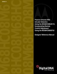
![mbed NXP LPC11U24 Schaltplan 010.2 [PDF/57KB]](https://img.yumpu.com/43869567/1/190x135/mbed-nxp-lpc11u24-schaltplan-0102-pdf-57kb.jpg?quality=85)