HAYNES® 556™ alloy - Haynes International, Inc.
HAYNES® 556™ alloy - Haynes International, Inc.
HAYNES® 556™ alloy - Haynes International, Inc.
- No tags were found...

Create successful ePaper yourself
Turn your PDF publications into a flip-book with our unique Google optimized e-Paper software.
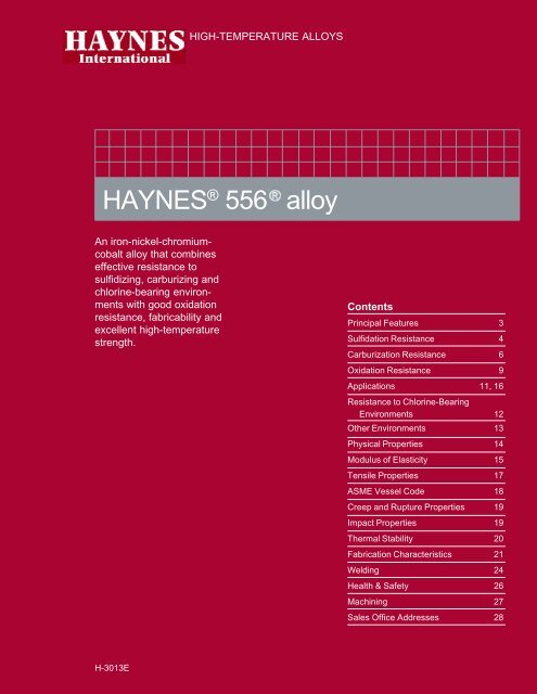
HIGH-TEMPERATURE ALLOYSHAYNES ® 556 <strong>alloy</strong>An iron-nickel-chromiumcobalt<strong>alloy</strong> that combineseffective resistance tosulfidizing, carburizing andchlorine-bearing environmentswith good oxidationresistance, fabricability andexcellent high-temperaturestrength.ContentsPrincipal Features 3Sulfidation Resistance 4Carburization Resistance 6Oxidation Resistance 9Applications 11, 16Resistance to Chlorine-BearingEnvironments 12Other Environments 13Physical Properties 14Modulus of Elasticity 15Tensile Properties 17ASME Vessel Code 18Creep and Rupture Properties 19Impact Properties 19Thermal Stability 20Fabrication Characteristics 21Welding 24Health & Safety 26Machining 27Sales Office Addresses 28H-3013EHAYNES ® 556 TM <strong>alloy</strong>
HAYNES ® 556 TM <strong>alloy</strong> 2 ©2005, <strong>Haynes</strong> <strong>International</strong>, <strong>Inc</strong>.
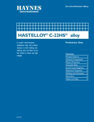
PRINCIPAL FEATURESHigh Strength and Resistanceto High-TemperatureCorrosionHAYNES ® 556 <strong>alloy</strong> is aniron-nickel-chromium-cobalt<strong>alloy</strong> that combines effectiveresistance to sulfidizing, carburizingand chlorine-bearingenvironments at high temperatureswith good oxidationresistance, fabricability, andexcellent high-temperaturestrength. It has also beenfound to resist corrosion bymolten chloride salts and othersalts, and is resistant to corrosionfrom molten zinc.Ease of FabricationHAYNES 556 <strong>alloy</strong> has excellentforming and weldingcharacteristics. It may beforged or otherwise hot-worked,providing that it is held at2150°F (1175°C) for a timesufficient to bring the entirepiece to temperature. As aconsequence of its goodductility, 556 <strong>alloy</strong> is alsoreadily formed by cold working.All hot- or cold-worked partsshould be annealed and rapidlycooled in order to restore thebest balance of properties.The <strong>alloy</strong> can be welded by avariety of techniques, includinggas tungsten arc (GTAW), gasmetal arc (GMAW), shieldedmetal arc (coated electrode),and resistance welding.Heat-TreatmentHAYNES 556 <strong>alloy</strong> is furnishedin the solution heat-treatedcondition, unless otherwisespecified. The <strong>alloy</strong> is normallysolution heat-treated at 2150°F(1175°C) and rapidly cooled orwater-quenched for optimumproperties. Heat treatments attemperatures lower than thesolution heat-treating temperaturemay cause precipitation ofsecondary phases.Available in PracticalProduct FormsHAYNES 556 <strong>alloy</strong> is availablein the form of plate, sheet, strip,billet, bar, wire, pipe and tubing.Applicable SpecificationsHAYNES 556 <strong>alloy</strong> is coveredby ASME Section VIII, Division 1,up to 1650°F (900°C) andASME Section I, (Code Case2010) up to 1200°F (650°C).ASTM specifications include B-435 (plate/sheet), B-572 (rod/bar), B-619 (welded pipe), B-622 (seamless pipe and tubing),and B-626 (welded tubing).AMS specifications are AMS5874 (sheet/strip/plate), AMS5877 (bar/forgings) and AMS5831 (wire). 556 weld wire iscovered by AWS specificationA5.9 (ER3556). The UNSnumber for HAYNES 556 <strong>alloy</strong>is R30556.ApplicationsHAYNES 556 <strong>alloy</strong> combinesproperties which make it highlyuseful for service at elevatedtemperaturein moderately toseverely corrosive environments.Applications caninclude tubing and structuralmembers in municipal andindustrial waste incinerators,rotary calciners and kilns forminerals processing, and nonrotatingcomponents in landbasedgas turbines burning lowgradefuels.In the chemical process industry,556 <strong>alloy</strong> is used for applicationsin rotary calciners,carbon regenerators, and inprocesses involving high-sulfurpetroleum feedstocks.In the metallurgical processindustry, 556 <strong>alloy</strong> is widelyused for hot-dip galvanizingfixtures, spinners and baskets,and for high speed furnacefans. 556 <strong>alloy</strong> is also employedin air preheaters ofdiesel engines, the inner coversof coil annealing furnaces, andin various high-temperatureapplications in the aerospaceindustry.Nominal Chemical Composition, Weight PercentFe Ni Co Cr Mo W Ta N Si Mn Al C La Zr31 a 20 18 22 3 2.5 0.6 0.20 0.4 1 0.2 0.10 0.02 0.02aAs Balance3HAYNES ® 556 TM <strong>alloy</strong>
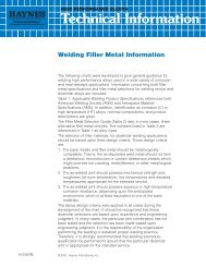
SULFIDATION RESISTANCEHAYNES ® 556 <strong>alloy</strong> is secondin resistance only to HAYNESHR-160 ® <strong>alloy</strong> to the types ofsulfur-bearing environments thatare present in many hightemperatureindustrial processes.This is due partly to itscomparatively low nickel contentcoupled with the importantaddition of cobalt, the highchromium level, and the carefullybalanced minor elements.For comparison, data illustratingthe relative sulfidation resistanceof INCONEL ® <strong>alloy</strong> 601,HASTELLOY ® X <strong>alloy</strong>, <strong>alloy</strong>s600 and 800H, and Type 310stainless steel are shown in theaccompanying photomicrographs.556 <strong>alloy</strong> had littlesulfide penetration or wastageafter 215 hours of exposure inan Ar+5%H 2+5%CO+1%CO 2+0.15%H 2S+0.1%H 2O test gas at1800°F (980°C). By contrast,<strong>alloy</strong>s such as INCONEL <strong>alloy</strong>601 were completely destroyed,while other materials sufferedsevere wastage and sulfidepenetration or pitting.Comparative Sulfidation Resistance at 1800°F (980°C) for 215 Hours(Width of Micros Indicates Original Sample Thickness)46983 4700647021HAYNES 556 <strong>alloy</strong>Average Metal Affected =2.0 Mils (50 µm)/SideType 310 stainless steelAverage Metal Affected =7.4 Mils (190 µm)/SideAlloy 800HAverage Metal Affected =23.2 Mils (590 µm)/Side4717547031 47172HASTELLOY X <strong>alloy</strong>Average Metal Affected =>22 Mils (560 µm)/SideINCONEL <strong>alloy</strong> 601Average Metal Affected =>22 Mils (560 µm)/SideAlloy 600Average Metal Affected =>22 Mils (560 µm)/SideSulfidation Resistance at Other TemperaturesMaterialHR-160 ® <strong>alloy</strong>556 <strong>alloy</strong>Type 310<strong>alloy</strong> 800HX <strong>alloy</strong><strong>alloy</strong> 600<strong>alloy</strong> 6011400°F (760°C)*Metal Loss Average Metal Affected**Mils µm Mils µm0.2 5 1.1 302.5 65 3.8 956.2 155 9.1 2307.1 180 11.2 285>29.5 >750 Perforated>21.7 >560 Perforated>29.5 >750 Perforated1600°F (871°C)*Metal Loss Average Metal AffectedMils µm Mils µm0.1 3 3.8 955.2 130 11.7 2959.5 240 13.5 34511.7 295 19.2 490>21.7 >550 Consumed>21.7 >550 Consumed>21.7 >550 Perforated*215 Hour Exposure in Ar+5% H 2+5%CO+1% CO 2+0.15%H 2S+0.10%H 2O**Metal Loss + Average Internal PenetrationHAYNES ® 556 TM <strong>alloy</strong> 4
Field Experience - Municipal Waste <strong>Inc</strong>ineratorSamples were exposed for 950hours in the superheater sectionof a municipal waste incinerator.Combustion gas temperatureswere about 1475°F (800°C) withexcursions to 1740°F (950°C).The mode of corrosion observedwas oxidation/sulfidation, althoughalkali chloride compoundswere known to be present.HAYNES ® 556 <strong>alloy</strong> was foundto be one of the best <strong>alloy</strong>s forresisting this highly corrosiveenvironment.Maximum Metal Affected (mm)0.1 0.2 0.3 0.4 0.5 0.6 0.7 0.8 0.9HAYNES 188 <strong>alloy</strong>HAYNES 556 <strong>alloy</strong>INCOLEL <strong>alloy</strong> 617Type 309 stainless steelHASTELLOY X <strong>alloy</strong>5 10 15 20 25 30 35Maximum Metal Affected (mils)Field Experience - Aluminum Remelting FurnaceSamples of tubing were exposedfor 1150 hours in the recuperatorof an aluminum remelting furnaceproducing 1250°F (675°C) fluegases. The tube samples wereinternally cooled by combustionpreheat air the same as theoperating recuperator tubes. Themode of corrosion observed wascombined attack by alkali sulfatesand chlorides together withoxidation. HAYNES 556 <strong>alloy</strong>exhibited outstanding resistanceto corrosion in this environment.Maximum Metal Affected (mm)0.1 0.2 0.3 0.4 0.5 0.6 0.7 0.8 0.9HAYNES 556 <strong>alloy</strong>625 <strong>alloy</strong>HASTELLOY X <strong>alloy</strong>Type 310 stainlessType 316 stainlessType 304 stainless5 10 15 20 25 30 35Maximum Metal Affected (mils)5HAYNES ® 556 TM <strong>alloy</strong>
CARBURIZATION RESISTANCEHAYNES ® 556 <strong>alloy</strong> hasexcellent resistance to carburization,as measured in bothmixed gas exposure tests andpacked graphite exposure tests.Results for these tests arepresented in the followingpages.All results are presented interms of the mass of carbonabsorption per unit area, whichwas obtained from the equationM = C(W/A) where M = themass of carbon absorption perunit area (mg/cm 2 ). C = differencein carbon (weightfraction) before and afterexposure , W = weight of theunexposed specimen (mg) andA = surface area of the specimenexposed to the test environment(cm 2 ).Packed Carburization ResistanceCarbon absorption observed for556 <strong>alloy</strong> following 500 hourexposure in packed graphite at1800°F (980°C) was negligible,as shown below. Similarresistance was exhibited byHAYNES HR-120 ® <strong>alloy</strong>. Thisis in contrast to other <strong>alloy</strong>stested, all of which exhibitedmeasurable carbon absorption.In particular, the resistanceto carburization of 556<strong>alloy</strong> was significantly betterthan that for the stainless steeltype materials.1210500 Hours @ 1800°F (980°C)in packed graphiteCarbon Absorption (mg/cm 2 )86420HR-120 ®<strong>alloy</strong>556 TM<strong>alloy</strong>230 ®<strong>alloy</strong><strong>alloy</strong>601RA330 ®<strong>alloy</strong>310Stainless253 MA ®<strong>alloy</strong>Mixed Gas Carburization TestsCarbon absorption observed for556 <strong>alloy</strong> following exposure atboth 1700°F (925°C) and1800°F (980°C) to a carburizinggas mixture was significantlylower than that for most othermaterials tested. This is shownin the graphs on the followingpages. For these tests, theexposure was performed in agas environment consisting of(by volume %) 5.0% H 2, 5.0%CO, 5.0% CH 4and the balanceargon. The calculated equilibriumcomposition (volume %) at1800°F (980°C) and one atmwas 14.2% H 2, 4.8%CO,0.003% CO 2, 0.026% CH 4,0.011% H 2O and the balanceargon. The activity of carbonwas 1.0 and the partial pressureof oxygen was 9 x 10 -22 atm at1800°F (980°C).HAYNES ® 556 TM <strong>alloy</strong> 6
Comparative 1700°F (925°C) Mix Gas Carburization TestsHAYNES ® 556 TM <strong>alloy</strong>1700°F (925°C) for 217 HoursAlloy 800HAlloy 600HASTELLOY X <strong>alloy</strong>INCONEL <strong>alloy</strong> 601INCONEL <strong>alloy</strong> 617Type 310 stainless steel12 3 4 5 6 7Carbon Absorption Per Unit Area (mg/cm 2 )Typical Carburized Microstructures (Unetched) After ExposureFor 215 Hours At 1700°F (925°C)4486144708HAYNES 556 <strong>alloy</strong>Type 310 Stainless Steel7HAYNES ® 556 TM <strong>alloy</strong>
Comparative 1800°F (980°C) Mixed Gas Carburization TestsAlloy 800H1800°F (980°C) for 55 HoursHAYNES ® 556 TM <strong>alloy</strong>HASTELLOY X <strong>alloy</strong>Alloy 600INCONEL <strong>alloy</strong> 601INCONEL <strong>alloy</strong> 61712 3 4 5 6 7Carbon Absorption Per Unit Area (mg/cm 2 )Typical Carburized Microstructures (Unetched) After ExposureFor 55 Hours At 1800°F (980°C)4471444876HAYNES 556 <strong>alloy</strong> INCONEL <strong>alloy</strong> 617Note: Alloy 617 is carburized to the center of the sample.HAYNES ® 556 TM <strong>alloy</strong> 8
OXIDATION RESISTANCEHAYNES ® 556 <strong>alloy</strong> exhibitsgood resistance to both air andcombustion gas oxidizingenvironments, and can be usedfor long-term exposure attemperatures up to 2000°F(1095°C). For exposures ofshort duration, 556 <strong>alloy</strong> can beused at higher temperatures.Comparative Oxidation Resistance in Flowing Air*MaterialX <strong>alloy</strong>556 <strong>alloy</strong><strong>alloy</strong> 601<strong>alloy</strong> 800H446 SS316 SS1800°F (980°C) - 1008 Hours 2000°F (1095°C) - 1008 HoursMetal Loss Average Metal Affected** Metal Loss Average Metal AffectedMils µm Mils µmMils µm Mils µm0.3 8 0.9 251.5 40 2.7 700.4 10 1.1 301.0 25 2.6 650.5 15 1.3 351.2 30 2.6 650.9 25 1.8 455.4 135 7.4 1901.3 35 2.3 6013.1 335 14.5 37012.4 315 14.3 365>69.0 >1750 ConsumedSamples cycled to room temperature once-a-week* Flowing air at a velocity of 7.0 feet/minute (212.0 cm/minute) past the samples.** Metal Loss + Average Internal PenetrationMetallographic Technique used for Evaluating Environmental Tests1. Metal Loss = (A - B)/22. Average Internal Penetration = C3. Maximum Internal Penetration = D4. Average Metal Affected = ((A - B)/2) + C5. Maximum Metal Affected = ((A - B)/2) + D9HAYNES ® 556 TM <strong>alloy</strong>
Comparative Oxidation in Flowing Air 1800°F (980°C) for 1008 HoursMicrostructures shown are forcoupons exposed for 1008hours at 1800°F (980°C) in airflowing 7.0 feet/minute (212.0cm/minute) past the samples.Samples were descaled bycathodically charging thecoupons while they wereimmersed in a molten saltsolution. The black area shownat the top of each picturerepresents actual metal lossdue to oxidation. The dataclearly show HAYNES ® 556<strong>alloy</strong> to be superior to bothRA330 ® <strong>alloy</strong> and Type 304stainless steel as well as theother iron-base <strong>alloy</strong>s shown inthe table on the previous page.45626HAYNES 556 <strong>alloy</strong>Average Metal Affected =1.1 mils (20 µm)49258RA330 <strong>alloy</strong>Average Metal Affected =4.3 mils (110 µm)Type 304 Stainless SteelAverage Metal Affected =8.1 mils (205 µm)Comparative Burner Rig Oxidation Resistance 1000 Hour Exposure at 1800°F (980°C)Material230 ® <strong>alloy</strong>556 <strong>alloy</strong>RA330 <strong>alloy</strong>MULTIMET ® <strong>alloy</strong><strong>alloy</strong> 800HType 310 Stainless Steel<strong>alloy</strong> 600<strong>alloy</strong> 601*Metal Loss + Maximum Internal PenetrationOxidation Test ParametersBurner rig oxidation tests wereconducted by exposing, in arotating holder, samples 0.375inch x 2.5 inches x thickness(9.5mm x 64mm x thickness) toHAYNES ® 556 TM <strong>alloy</strong>Metal LossMils µm0.8 0.021.7 0.047.8 0.2011.8 0.3012.3 0.3113.7 0.3512.3 0.313.0 0.08**Extrapolated from 917 hoursthe products of combustion offuel oil (2 parts No. 1 and 1 partNo. 2) burned at a ratio of air tofuel of about 50:1. (Gasvelocity was about 0.3 mach).Samples were automatically10Average Metal Affected*Mils µm3.5 0.096.2 0.1611.8 0.3014.8 0.3815.3 0.3916.5 0.4217.8** 0.45**20.0 0.51removed from the gas streamevery 30 minutes and fan cooledto less than 500°F (260°C)and then reinserted into theflame tunnel.
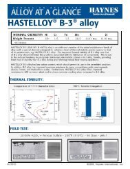
APPLICATIONSThis high-temperature fan for a heattreatfurnace of HAYNES 556 <strong>alloy</strong>was selected to resist a number ofatmospheres at 1700 to 1800°F (925to 980°C).HAYNES ® 556 <strong>alloy</strong> was chosen for componentsof this waste ash handling system operatingat 1650°F (900°C). It has more than doubledthe life of previously used stainless steel.A deposit of HAYNES 556 <strong>alloy</strong> protectselbows in a piping system at a titaniumdioxide plant. The elbows, coated with 556<strong>alloy</strong> has lasted over hour times as long asthose hardfaced with a cobalt-base <strong>alloy</strong>.The inside of the elbow is scoured byabrasive TiO 2and corrosive Cl 2at temperaturesto 1600°F (870°C).HAYNES 556 refractory anchors haveoutperformed other <strong>alloy</strong>s in this tailgasburner which removes high-sulfur gasesfrom effluent of refining operations.11HAYNES ® 556 TM <strong>alloy</strong>
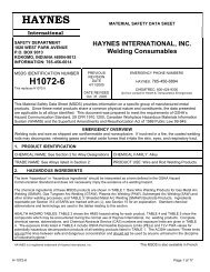
RESISTANCE TO CHLORINE-BEARING ENVIRONMENTSHAYNES ® 556 <strong>alloy</strong> can beconsidered resistant to hightemperatureoxidizing environmentscontaining chlorine.Although not as resistant asHAYNES 214 <strong>alloy</strong> at temperaturesabove 1650°F(900°C), 556 <strong>alloy</strong> has resistancecomparable to that of 214<strong>alloy</strong> at temperatures at orbelow 1650°F (900°C). This isshown by the test results givenfor 400 hour exposures at1650°F (900°C) in a flowing gasmixture of Ar+20%O 2+0.25%Cl 2. Note that 556 <strong>alloy</strong> showsvery low metal loss compared tomost of the <strong>alloy</strong>s tested, whichincluded <strong>alloy</strong>s 600, 625,INCONEL <strong>alloy</strong> 601 andHASTELLOY C-276 <strong>alloy</strong>.47535Alloy 60047263HAYNES 556 <strong>alloy</strong>1412AverageInternalPenetrationMetal Loss Ar-20%O 2-0.25%Cl 2for 400 hours1650°F (900°C)C-276350300Average Metal Affected (mils)10864214 5566006016252502001501002500HAYNES ® 556 TM <strong>alloy</strong> 12
OTHER HIGH TEMPERATURE ENVIRONMENTSMolten Chloride SaltsMaterialHAYNES 188 <strong>alloy</strong>HASTELLOY X <strong>alloy</strong>HAYNES 556 <strong>alloy</strong>Type 304 stainless steelType 310 stainless steelAlloy 600INCONEL <strong>alloy</strong> 601HAYNES ® 556 <strong>alloy</strong> exhibitsreasonable resistance to neutralNaCl-KCl-BaCl 2-type heattreatingsalts at temperaturesup to 1550°F (845°C) basedupon actual field tests in amolten salt pot heat treatingfacility. Coupons were exposedfor 30 days.Average Metal AffectedMils mm28 0.738 1.042 1.174 1.979 2.094 2.4115 2.9Phosphorus-Bearing Combustion EnvironmentMaterialHASTELLOY X <strong>alloy</strong>HAYNES 556 <strong>alloy</strong>HAYNES 214 <strong>alloy</strong>HASTELLOY S <strong>alloy</strong>HAYNES 188 <strong>alloy</strong>Alloy 800HType 304 stainless steelBased upon field tests performedin the combustionchamber of a fluid bed dryerused to dry sodium tripolyphosphatecompounds, HAYNES556 <strong>alloy</strong> exhibits very goodresistance to corrosion causedby formation of low-meltingpoint eutectics involving phosphorus.Samples were exposed30 days at a temperatureof about 1475°F (800°C).Maximum Metal AffectedMils µm3.0 756.0 1508.0 2059.0 2309.0 23011.0 28015.0 380Molten ZincResistance to molten zinc is animportant consideration forstructural components ingalvanizing operations. Laboratorytests were performed at850°F (455°C) for 50 hours inmolten zinc to determinesuitability for such operations.Results are given below:MaterialHAYNES 556 <strong>alloy</strong>HAYNES 25 <strong>alloy</strong>HAYNES 188 <strong>alloy</strong>1010 Carbon Steel446 Stainless SteelMetal Loss* mils (µm)1.6 412.3 582.5 649.2 2349.3 236MaterialAlloy 800H304 Stainless SteelHAYNES 625 <strong>alloy</strong>HASTELLOY X <strong>alloy</strong>**dissolvedMetal Loss* mils (µm)11.0 28014.1 358>24.0** >610**>24.0** >610***no internal attack noted for any of the <strong>alloy</strong>s tested13HAYNES ® 556 TM <strong>alloy</strong>
TYPICAL PHYSICAL PROPERTIESTemp., °F British Units Temp., °C Metric UnitsDensity Room 0.297 lb/in. 3 Room 8.23 g/cm. 3Melting Temperature 2425-2580 1330-1415Electrical Resistivity Room 37.5 microhm-in. Room 95.2 microhm-cm200 38.7 microhm-in. 100 98.6 microhm-cm400 40.5 microhm-in. 200 102.6 microhm-cm600 42.1 microhm-in. 300 106.5 microhm-cm800 43.5 microhm-in. 400 109.5 microhm-cm1000 44.7 microhm-in. 500 112.5 microhm-cm1200 45.7 microhm-in. 600 115.1 microhm-cm1400 46.6 microhm-in. 700 117.2 microhm-cm1600 47.3 microhm-in. 800 119.0 microhm-cm1800 48.0 microhm-in. 900 120.7 microhm-cm2000 48.6 microhm-in. 1000 122.3 microhm-cm1100 123.7 microhm-cmThermal Diffusivity Room 4.5 x 10 -3 in. 2 /sec. Room 28.7 x 10 -3 cm 2 /sec.200 4.8 x 10 -3 in. 2 /sec. 100 31.2 x 10 -3 cm 2 /sec.400 5.3 x 10 -3 in. 2 /sec. 200 34.2 x 10 -3 cm 2 /sec.600 5.8 x 10 -3 in. 2 /sec. 300 37.0 x 10 -3 cm 2 /sec.800 6.3 x 10 -3 in. 2 /sec. 400 39.7 x 10 -3 cm 2 /sec.1000 6.7 x 10 -3 in. 2 /sec. 500 42.3 x 10 -3 cm 2 /sec.1200 7.1 x 10 -3 in. 2 /sec. 600 44.8 x 10 -3 cm 2 /sec.1400 7.5 x 10 -3 in. 2 /sec. 700 47.0 x 10 -3 cm 2 /sec.1600 7.7 x 10 -3 in. 2 /sec. 800 48.8 x 10 -3 cm 2 /sec.1800 8.0 x 10 -3 in. 2 /sec. 900 50.3 x 10 -3 cm 2 /sec.2000 8.2 x 10 -3 in. 2 /sec. 1000 51.6 x 10 -3 cm 2 /sec.1100 52.8 x 10 -3 cm 2 /sec.Thermal Conductivity Room 77 Btu-in./ft. 2 hr.-°F Room 11.1 W/m-K200 90 Btu-in./ft. 2 hr.-°F 100 13.1 W/m-K400 107 Btu-in./ft. 2 hr.-°F 200 15.4 W/m-K600 122 Btu-in./ft. 2 hr.-°F 300 17.3 W/m-K800 135 Btu-in./ft. 2 hr.-°F 400 19.0 W/m-K1000 148 Btu-in./ft. 2 hr.-°F 500 20.8 W/m-K1200 160 Btu-in./ft. 2 hr.-°F 600 22.4 W/m-K1400 173 Btu-in./ft. 2 hr.-°F 700 24.0 W/m-K1600 185 Btu-in./ft. 2 hr.-°F 800 25.5 W/m-K1800 197 Btu-in./ft. 2 hr.-°F 900 27.2 W/m-K2000 210 Btu-in./ft. 2 hr.-°F 1000 28.9 W/m-K1100 30.4 W/m-KHAYNES ® 556 TM <strong>alloy</strong> 14
Typical Physical Properties (continued)Temp., °F British Units Temp., °C Metric UnitsSpecific Heat Room 0.111 Btu/lb.-°F Room 464 J/Kg-K200 0.113 Btu/lb.-°F 100 475 J/Kg-K400 0.118 Btu/lb.-°F 200 493 J/Kg-K600 0.122 Btu/lb.-°F 300 508 J/Kg-K800 0.126 Btu/lb.-°F 400 523 J/Kg-K1000 0.130 Btu/lb.-°F 500 538 J/Kg-K1200 0.133 Btu/lb.-°F 600 552 J/Kg-K1400 0.135 Btu/lb.-°F 700 561 J/Kg-K1600 0.140 Btu/lb.-°F 800 570 J/Kg-K1800 0.147 Btu/lb.-°F 900 595 J/Kg-K2000 0.152 Btu/lb.-°F 1000 618 J/Kg-K1100 638 J/Kg-KMean Coefficient of 70-200 8.1 microinches/in.-°F 25-100 14.7 10 -6 m/m-°CThermal Expansion 70-400 8.2 microinches/in.-°F 25-200 14.9 10 -6 m/m-°C70-600 8.4 microinches/in.-°F 25-300 15.1 10 -6 m/m-°C70-800 8.6 microinches/in.-°F 25-400 15.4 10 -6 m/m-°C70-1000 8.8 microinches/in.-°F 25-500 15.7 10 -6 m/m-°C70-1200 9.0 microinches/in.-°F 25-600 16.1 10 -6 m/m-°C70-1400 9.2 microinches/in.-°F 25-700 16.4 10 -6 m/m-°C70-1600 9.4 microinches/in.-°F 25-800 16.7 10 -6 m/m-°C70-1800 9.5 microinches/in.-°F 25-900 17.0 10 -6 m/m-°C70-2000 9.6 microinches/in.-°F 25-1000 17.1 10 -6 m/m-°C25-1100 17.1 10 -6 m/m-°CDYNAMIC MODULUS OF ELASTICITYDynamicDynamicModulus ofModulus ofElasticity,Elasticity,Temp., °F 10 6 psi Temp., °C GPaRoom 29.7 x 10 6 psi Room 205 GPa200 29.1 x 10 6 psi 100 200 GPa400 28.2 x 10 6 psi 200 195 GPa600 26.9 x 10 6 psi 300 187 GPa800 25.6 x 10 6 psi 400 179 GPa1000 24.4 x 10 6 psi 500 172 GPa1200 23.1 x 10 6 psi 600 164 GPa1400 21.8 x 10 6 psi 700 155 GPa1600 20.9 x 10 6 psi 800 148 GPa1800 20.1 x 10 6 psi 900 143 GPa1000 138 GPa15HAYNES ® 556 TM <strong>alloy</strong>
APPLICATIONS16492HAYNES ® 556 spinner baskets are continuallycycled through molten zinc at 850°F (455°C) forhot dip galvanizing. After 16 months of operationthe 556 baskets showed no measureable metalloss from the molten zinc exposure. 1538329403-515-3116This salt pot heat-treat basket ofHAYNES 556 <strong>alloy</strong> for heat treatingaircraft components at 1600°F to600°F (870°C to 315°C) in moltensalt has outperformed stainlesssteels 3 times because of 556 <strong>alloy</strong>sexcellent ductility, thermal fatigueresistance and improved strengthlevels at 1600°F (870°C).1795630567-508556 <strong>alloy</strong> vacuum carburizing furnace retort.556 <strong>alloy</strong> upgrades MULTIMET ® <strong>alloy</strong>stator vanes in industrial turbines.HAYNES ® 556 TM <strong>alloy</strong>16
TYPICAL TENSILE PROPERTIESCold-Rolled and Solution Annealed Sheet, 0.033 to 0.109 <strong>Inc</strong>hes (0.8 to 2.8 mm) Thick*TestTemperatureUltimateTensileStrengthYield Strengthat 0.2% OffsetElongation in2 in. (50.8 mm)°F °CKsiMPaKsiMPa%RoomRoom118.1 81559.5 41047.71000 54093.4 64534.9 24054.41200 65085.4 59032.8 22552.41400 76068.5 47032.0 22049.11600 87047.6 33028.6 19552.61800 98028.0 19515.5 10563.32000 109514.8 1008.0 5555.4* Based upon 10 or more Tests per conditionComparative Yield Strengths (Sheet)Test Temperature, °C100300500700900110060080705000.2% Yield Strength (Ksi)60504030800H5564003002000.2% Yield Strength (MPa)2010310stainless600100200 400 600 800 1000 1200 1400 1600 1800 2000Test Temperature, °F17HAYNES ® 556 TM <strong>alloy</strong>
Typical Tensile Properties (continued)Hot-Rolled and Solution Annealed Plate, 0.250 to 0.500 <strong>Inc</strong>hes (6.4 to 12.7 mm) Thick*TestTemperature°F °CUltimateTensileStrengthKsi MPaYield Strengthat 0.2% OffsetKsi MPaElongation in2 in. (50.8 mm)%RoomRoom116.4 80554.6 37551.41000 5401200 65090.3 62583.1 57530.6 21030.6 21060.357.41400 76068.5 47029.3 20052.61600 8701800 98049.3 34030.7 21027.9 19018.5 13069.183.92000 109516.1 1108.7 6095.2* Based upon 56 TestsASME VESSEL CODE ALLOWABLE STRESSESHAYNES ® 556 <strong>alloy</strong> is approved forASME Vessel Code Section I constructionto 1200°F (650°C) under Code Case No.2010 and Section VIII Division 1 constructionto 1650°F (900°C). Allowable stressesare reprinted here by permission of theASME.NOTE (1)Due to the relatively low yield strength of this material, thesehigher stress values were established at temperatures wherethe short time tensile properties govern to permit the use ofthese <strong>alloy</strong>s where slightly greater deformation is acceptable.These higher stress values exceed 67%, but do not exceed90% of the yield strength at temperature. Use of these stressmay result in dimensional changes due to permanent strain.These stress values are not recommended for flanges ofgasketed joints or other applications where slight amounts ofdistortion can cause leakage or malfunction.HAYNES ® 556 TM <strong>alloy</strong>ASME Vessel Code Allowable StressesMetalMaximum Allowable Stress ValuesTemperaturesNot ExceedingStandardNote (1)°F °C Ksi (MPa) Ksi (MPa)100 37 25.0 (172) 25.0 (172)200 93 25.0 (172) 25.0 (172)300 149 23.1 (159) 24.5 (168)400 204 21.3 (146) 23.7 (163)500 260 20.1 (138) 23.1 (159)600 315 19.3 (133) 22.8 (157)650 343 19.0 (131) 22.7 (156)700 371 18.7 (129) 22.5 (155)750 398 18.5 (127) 22.4 (154)800 426 18.2 (125) 22.3 (153)850 454 18.0 (124) 22.2 (153)900 482 17.8 (122) 22.1 (152)950 510 17.6 (121) 21.8 (150)1000 537 17.4 (120) 21.6 (148)1050 565 17.2 (118) 21.4 (147)1100 593 17.1 (118) 20.8 (143)1150 621 16.9 (116) 16.9 (116)1200 648 13.6 (93) 13.6 (93)1250 676 10.9 (75) 10.9 (75)1300 7048.8 (60) 8.8 (60)1350 7327.0 (48) 7.0 (48)1400 7605.6 (38) 5.6 (38)1450 7874.5 (31) 4.5 (31)1500 8153.6 (25) 3.6 (25)1550 8432.8 (19) 2.8 (19)1600 8712.2 (15) 2.2 (15)1650 8981.8 (12) 1.8 (12)18
TYPICAL CREEP AND STRESS-RUPTURE PROPERTIESSolution Annealed Sheet, Plate and BarTemperature°F °C1200 6501300 7051400 7601500 8151600 8701700 9251800 980Creep,Percent0.51.0Rupture0.51.0Rupture0.51.0Rupture0.51.0Rupture0.51.0Rupture0.51.0Rupture0.51.0RuptureAverage Initial Stress, Ksi (MPa)*to Produce Specified Creep and Rupture10 Hours 100 Hours 1,000 Hours 10,000 Hours44.0 (305) 32.0 (220) 24.0 (165) - -49.0 (340) 35.0 (240) 25.5 (175) 18.5 (130)- - 53.0 (365) 38.0 (260) 27.5 (190)29.0 (200) 21.0 (145) 15.0 (105) - -33.0 (230) 24.0 (165) 17.5 (120) 12.5 (86)52.0 (360) 37.0 (255) 26.0 (180) 17.0 (115)19.0 (130) 13.5 (93) 9.4 (65) - -22.0 (150) 16.0 (110) 11.5 (79) 8.5 (59)35.0 (240) 25.0 (170) 17.5 (120) 11.9 (82)13.0 (90) 9.0 (62) 6.5 (45) - -15.0 (105) 11.0 (76) 8.2 (57) 6.0 (41)25.0 (170) 17.0 (115) 11.8 (81) 7.6 (52)8.9 (61) 6.4 (44) 4.6 (32) - -10.0 (69) 7.5 (52) 5.5 (38) 4.1 (28)17.0 (115) 11.5 (79) 7.5 (52) 4.9 (34)6.2 (43) 4.5 (31) 3.2 (22) - -7.2 (50) 5.0 (34) 3.5 (24) 2.5 (17)12.0 (83) 7.6 (52) 4.8 (33) 3.0 (21)4.4 (30) 3.0 (21) 2.0 (14) - -5.0 (34) 3.4 (23) 2.3 (16) 1.6 (11)7.5 (52) 4.8 (33) 3.0 (21) 1.9 (13)TYPICAL IMPACT PROPERTIESMaterial<strong>alloy</strong> 800H<strong>alloy</strong> 600556 <strong>alloy</strong>188 <strong>alloy</strong>S <strong>alloy</strong><strong>alloy</strong> 625X <strong>alloy</strong>V-Notch Impact Strength 1Room Temperatureft.-lb.Joules239 2 324 2180 244177 2 240 2143 194140 19081 11054 731Average of 4 or more tests2Samples did not break19HAYNES ® 556 TM <strong>alloy</strong>
THERMAL STABILITYHAYNES ® 556 exhibitsreasonable retained ductilityafter long term thermal exposureat intermediate temp-eratures. It does not exhibitsignificant sigma phase formationeven after 16,000 hoursexposure at 1000 to 1600°F(540 to 870°C). Principalphases precipitated from solidsolution are carbides andcarbonitrides.Room-Temperature Tensile Properties of Bar Following Thermal Exposure*ExposureTemperatureUltimateTensileStrengthYield Strengthat 0.2% OffsetElongation in2 in. (50.8 mm)°F °CHoursKsiMPaKsiMPa%1200 6500113.4 78062.5 43046.51000120.5 83059.7 41036.04000121.2 83557.4 39533.08000127.3 88059.8 41029.41400 7600113.4 78062.5 43046.51000128.7 88560.8 42024.84000127.1 87557.4 39525.88000125.1 86554.6 37524.71600 8700113.4 78062.5 43046.51000112.9 78052.3 36032.84000111.5 77042.8 29529.08000108.1 74543.9 30529.5* Average of three tests for each conditionElevated-Temperature Tensile Properties of Bar Following 16,000-Hour Thermal Exposures*TestTemperatureUltimateTensileStrengthYield Strengthat 0.2% OffsetElongation in2 in. (50.8 mm)°F °CKsiMPaKsiMPa%1000 53795.7 66037.4 26048.01200 64888.8 61037.8 26023.41400 76072.3 50035.1 24025.31600 87142.1 29021.9 15029.5HAYNES ® 556 TM <strong>alloy</strong> 20
Thermal Stability (continued)Room-Temperature Tensile Properties of Sheet Following1000-Hour Thermal Exposures*TestTemperature°F °CUltimateTensileStrengthKsi MPaYield Strengthat 0.2% OffsetKsi MPaElongation in2 in. (50.8 mm)%RoomRoom118.1 81559.5 41047.71200 6481400 760118.4 815118.8 82053.4 37053.8 37037.917.01600 871111.0 76546.6 32020.4* Average of two or more testsFABRICATION CHARACTERISTICSHeat TreatmentHAYNES ® 556 <strong>alloy</strong> isnormally final solution heattreatedat 2150°F (1175°C) fora time commensurate withsection thickness. Solutionheat-treating can be performedat temperatures as low as about2125°F (1165°C), but resultingmaterial properties will bealtered accordingly. Annealingduring fabrication can beperformed at even lowertemperatures, but a final,subsequent solution heattreatment is needed to produceoptimum properties and structure.Please refer to followingsections and publication H-3159for additional information.Typical Hardness PropertiesHardness, R A7472706866646260Sheet Hardness atRoom Temperature454035302520Hardness, R CSolution AnnealedRoom Temperature HardnessFormR BSheet 91.0Plate 96.558560 10 20 30 40 50% Cold Reduction21HAYNES ® 556 TM <strong>alloy</strong>
Fabrication Characteristics (continued)Effect of Cold Reduction upon Room-Temperature Tensile Properties*PercentColdSubsequentAnnealUltimateTensileStrengthYield Strengthat 0.2% OffsetElongation in2 in. (50.8 mm)ReductionTemperatureKsiMPaKsiMPa%0115.0 79552.9 36550.710127.8 88093.3 64534.82030None142.1 980172.6 1190113.3 780144.1 99523.512.040189.3 1305155.8 107510.150204.2 1410169.7 11708.00114.7 79052.6 36544.8102030401850°F(1010°C)for 5 min.121.6 840127.0 875135.2 930133.3 92076.9 53088.8 61092.7 64080.0 55034.330.326.630.650135.0 93083.0 57031.70115.8 80052.9 36545.2102030401950°F(1065°C)for 5 min.122.2 845124.7 860125.1 865128.1 88576.8 53076.8 53066.0 45571.4 49036.934.838.336.750131.0 90577.9 53533.40117.0 80554.3 37547.0102030402050°F(1121°C)for 5 min.117.4 810120.1 830123.6 850124.7 86055.3 38058.4 40563.5 44066.9 46048.045.443.042.450126.6 87570.8 48535.0* Based upon rolling reductions taken upon 0.120-inch (3.0mm) thick sheet.Duplicate testsHAYNES ® 556 TM <strong>alloy</strong> 22
Fabrication Characteristics (continued)Typical Microstructure(ASTM 5 grain size) Annealed at 2150°F (1175°C)50244Etchant: 95mlHCl plus 5gmoxalic acid, 4 volts23HAYNES ® 556 TM <strong>alloy</strong>
WELDINGHAYNES ® 556 <strong>alloy</strong> is readilywelded by gas tungsten arc(GTAW), gas metal arc(GMAW), shielded metal arc(coated electrode), and resistancewelding techniques.Submerged arc welding is notrecommended as this processis characterized by high heatinput to the base metal andslow cooling of the weld. Thesefactors can increase weldrestraint and promote cracking.Base Metal PreparationThe joint surface and adjacentarea should be thoroughlycleaned before welding. Allgrease, oil, crayon marks, sulfurcompounds and other foreignmatter should be removed. It ispreferable, but not necessary,that the <strong>alloy</strong> be in the solutionannealedcondition whenwelded.Filler Metal SelectionMatching composition fillermetal is recommended forjoining 556 <strong>alloy</strong>. For shieldedmetal-arc welding, MULTIMETelectrodes (AMS 5795) aresuggested. For dissimilar metaljoining of 556 <strong>alloy</strong> to nickel- orcobalt-base materials, 556 fillermetal will generally be a goodselection, but HASTELLOY S<strong>alloy</strong> (AMS 5838A) orHASTELLOY W <strong>alloy</strong> (AMS5786B, 5787A) welding productsmay be used. For dissimilarwelding to iron-base materials,556 filler metal is recommended.Please see publicationH-3159.Preheating, InterpassTemperatures and Post-Weld Heat TreatmentPreheat is not usually requiredso long as base metal to bewelded is above 32°F (0°C).Interpass temperatures generallyshould be low. Auxiliarycooling methods may be usedbetween weld passes, asneeded, providing that suchmethods do not introducecontaminants. Post-weld heattreatment is not normallyrequired for 556 <strong>alloy</strong>s.Nominal WeldingParametersNominal welding parametersare provided as a guide forperforming typical operations.These are based upon weldingconditions used in <strong>Haynes</strong><strong>International</strong>, <strong>Inc</strong>. laboratories.For further information, pleaseconsult <strong>Haynes</strong> publicationH-3159.Automatic Gas Tungsten Arc WeldingSquare Butt Joint - No Filler Metal AddedMaterial Thickness0.040" (1.0mm) 0.062" (1.6mm) 0.125" (3.2mm)Current (DCEN), amperes 45 75 110Voltage 8 8.5 9.5Travel Speed, in/min. (mm/min) 10 (254) 12 (305) 12 (305)Electrode Size-EWTH-2, in (mm) 1/16 (1.6) 3/32 (2.4) 1/8 (3.2)Electrode Shape 45° inc 45° inc 45° incCup Size #8 #8 #8Shielding Gas Flow, CFH (l/min.) 30 (14.2) 30 (14.2) 30 (14.2)Gas Type Argon Argon ArgonBacking Gas, CFH (l/min.) 10 (4.7) 10 (4.7) 10 (4.7)Gas Type Argon Argon ArgonHAYNES ® 556 TM <strong>alloy</strong> 24
Manual Gas Tungsten Arc WeldingV-or U-Groove - All Thicknesses 1/8" (3.2 mm) or greaterTechnique - Stringer BeadCurrent (DCEN), amperes - 120 root, 140-150 FillVoltage - 11 to 14Filler Metal - 1/8" diameter (3.2 mm) 556 <strong>alloy</strong>Travel Speed, ipm (mm/min) - 4 to 6 (102-152)Electrode Size-EWTH-2, in (mm) - 1/8" diameter (3.2 mm)Electrode Shape - 30° includedCup Size - #6 or largerGas Type - ArgonShielding Gas Flow, CFH (l/min.) - 30 to 35 (14.2 to 16.5)Backing Gas Flow, CFH (l/min.) - 10 (4.7) or back-gougeto sound metal and fillfrom root sidePreheat - AmbientInterpass Temperature Maximum - 200°F (93°C)Gas Metal Arc WeldingShort Circuiting Transfer Mode Spray Transfer ModeAll Thicknesses 0.090" All Thicknesses 0.156"and greater (2.3mm)and greater (4.0mm)Wire Type 556 <strong>alloy</strong> 556 <strong>alloy</strong>Wire Diameter, in (mm) 0.045 (1.1) 0.062 (1.6)Feed Speed, ipm (m/min) 170 to 190 (4.3 to 4.8) 160 to 170 (4.0 to 4.3)Current (DCEP), amperes 100 to 110 210 to 230Voltage 20 to 22 28 to 30Stickout, in (mm) 1/2-3/4 (12.7 to 19.1) 3/4 (19.1)Travel Speed, ipm (mm/min) 8 to 10 (203 to 254) 9 to 12 (229 to 305)Torch Gas Flow, CFH (l.min.) 40 (18.9) 40 (18.9)Gas Type A1025 (90% He, 7.5% Ar, Argon2.5% CO 2) or 75% Ar + 25% He)Shielded Metal Arc WeldingNo matching chemistry SMAWelectrodes are currently availablefor 556 <strong>alloy</strong>.MULTIMET electrodes (AMS5795) have been successfullyused to join 556 <strong>alloy</strong>. Typicalparameters for MULTIMETelectrodes (flat position) aregiven below.Electrode Diameter Voltage Current (DCEP) Travel Speedin (mm) amperes ipm (mm/min)3/32 (2.4) 22 - 24 45 - 75 3 - 5 (76 - 127)1/8 (3.2) 22 - 24 70 - 110 4 - 6 (102 - 152)5/32 (4.0) 23 - 25 110 - 140 4 - 6 (102 - 152)25HAYNES ® 556 TM <strong>alloy</strong>
Typical Tensile Properties, All-Weld Metal (GTAW)TestTemperatureUltimateTensileStrengthYield Strengthat 0.2% OffsetElongation in2 in. (50.8 mm)°F °CKsiMPaKsiMPa%RoomRoom107.3 74067.3 46543.11200 64871.4 49044.6 31039.41400 76055.2 38042.4 29038.91600 87132.8 22529.0 20051.91800 98229.2 20020.7 145125.750676Typical crack-free face and rootbends for welded 556 <strong>alloy</strong> 0.5inch (13 mm) plate and matchingfiller metal. Bend radius was 0.75inch (19 mm).HEALTH AND SAFETYWelding can be a safe occupation.Those in the weldingindustry, however, should beaware of the potential hazardsassociated with welding fumes,gases, radiation, electric shock,heat, eye injuries, burns, etc.Also, local, municipal, state,and federal regulations (such asthose issued by OSHA) relativeto welding and cutting processesshould be considered.Nickel-, cobalt-, and iron-base<strong>alloy</strong> products may contain, invarying concentration, thefollowing elemental constituents:aluminum, cobalt, chromium,copper, iron, manganese,molybdenum, nickel andtungsten. For specific concentrationsof these and otherelements present, refer to theMaterial Safety Data Sheets(MSDS) available from <strong>Haynes</strong><strong>International</strong>, <strong>Inc</strong>.Inhalation of metal dust orfumes generated from welding,cutting, grinding, melting, ordross handling of these <strong>alloy</strong>smay cause adverse healtheffects such as reduced lungfunction, nasal and mucousmembrane irritation. Exposureto dust or fumes which may begenerated in working with these<strong>alloy</strong>s may also cause eyeirritation, skin rash and effectson other organ systems.The operation and maintenanceof welding and cutting equipmentshould conform to theprovision of American NationalStandard ANSI/AWS Z49.1,"Safety in Welding and Cutting".Attention is especially called toSection 4 (Protection of Personnel)and 5 (Health Protectionand Ventilation) of ANSI/AWSZ49.1. Mechanical ventilation isadvisable and, under certainconditions such as a veryconfined space, is necessaryduring welding or cuttingoperations, or both, to preventpossible exposure to hazardousfumes, gases, or dust that mayoccur.Acknowledgements:INCONEL is a registered trademark of <strong>Inc</strong>o Family of Companies.RA330 is a registered trademarks of Rolled Alloys, <strong>Inc</strong>.253 MA is a registered trademark of Avesta Jernverks Aktiebolag.HAYNES ® 556 TM <strong>alloy</strong> 26
MACHININGHAYNES ® 556 <strong>alloy</strong> is similarin machining characteristics toother solid-solution-strengthenednickel-base <strong>alloy</strong>s. These<strong>alloy</strong>s as a group are classifiedas moderate to difficult tomachine; however, it should beemphasized that they can bemachined using conventionalmethods at satisfactory rates.As these <strong>alloy</strong>s will work-hardenrapidly, the keys to successfulmachining are to use lowerspeeds and feeds, and to takeheavier cuts than would beused for machining stainlesssteels. See <strong>Haynes</strong> <strong>International</strong>publication H-3159 formore detailed information.Normal Roughing (Turning / Facing)Use carbide C-2 / C-3 grade toolSpeed: 90 surface feet / minuteFeed: 0.010 in. / revolutionDepth of cut: 0.150 in.Negative rake square insert, 45° SCEA'1/32 in. nose radius. Tool holder: 5° negativeback and side rakes.Lubricant: Dry 2 , oil 3 or water-base 4,5 .Finishing (Turning / Facing)Use carbide C-2 / C-3 grade toolSpeed: 95-110 surface feet / minuteFeed: 0.005-0.007 in. / revolutionDepth of cut: 0.040 in.Positive rake square insert, if possible,45° SCEA' 1/32 in. nose radius. Tool holder:5° positive back and side rakes.Lubricant: Dry or water-base.DrillingUse high speed steel M-33 / M-40 series 6 / orT-15 grades*Speed: 10-15 surface feet / minute (200 RPMmaximum for 1/4 in. diameter or smaller)Lubricant: oil or water-base. Use coolant feeddrills if possible.Short, heavy-web drills with 135° crank shaftpoint. Thinning of web at point may reducethrust.Feed:0.001 in. rev. 1/8 in. dia.0.002 in. rev. 1/4 in. dia.0.003 in. rev. 1/2 in. dia.0.005 in. rev. 3/4 in. dia.0.007 in. rev. 1 in. dia.*Carbide drills not recommended, but may be used in some set-ups. See <strong>Haynes</strong> <strong>International</strong> publication H-3159 for details.Notes: 1 SCEA - Side cutting edge angle, or lead angle of the tool.2 At any point where dry cutting is recommended, an air jet directed on the tool may providesubstantial tool life increases. A water-base coolant mist may also be effective.3 Oil coolant should be a premium quality, sulfochlorinated oil with extreme pressure additives.A viscosity at 100°F of from 50 to 125 SSU is standard.4 Water-base coolant should be a 15:1 mix of water with either a premium quality, sulfochlorinatedwater soluble oil or a chemical emulsion with extreme pressure additives.5 Water-base coolants may cause chipping or rapid failure of carbide tools in interrupted cuts.6 M-40 series High Speed Steels include M-41 through M-46 at time of writing, others maybe added, and should be equally suitable.27HAYNES ® 556 TM <strong>alloy</strong>
STANDARD PRODUCTSBy Brand or Alloy Designation:HASTELLOY ® Corrosion-Resistant AlloysB-3 ® , C-4, C-22 ® , C-22HS ® , C-276, C-2000 ® , G-30 ® , G-35 ® , G-50 ® , HYBRID-BC1, and NHASTELLOY ® High-Temperature AlloysS, W, and XHAYNES ® High-Temperature Alloys25, R-41, 75, HR-120 ® , HR-160 ® , HR-224, 188, 214 ® , 230 ® , 230-W ® , 242 ® , 263, 282 ® , 556 ® , 617, 625,625SQ ® , 718, X-750, MULTIMET ® , NS-163, and WaspaloyCorrosion-Wear Resistant AlloyULTIMET ®HAYNES ® Titanium Alloy TubularTi-3Al-2.5VWear-Resistant Alloy6BStandard Forms: Bar, Billet, Plate, Sheet, Strip, Coils, Seamless or Welded Pipe & Tubing, PipeFittings, Flanges, Fittings, Welding Wire, and Coated ElectrodesProperties Data: The data and information in this publication arebased on work conducted principally by <strong>Haynes</strong> <strong>International</strong>,<strong>Inc</strong>. and occasionally supplemented by information from the openliterature, and are believed to be reliable. However, <strong>Haynes</strong>does not make any warranty or assume any legal liability orresponsibility for its accuracy, completeness, or usefulness,nor does <strong>Haynes</strong> represent that its use would not infringeupon private rights.Any suggestions as to uses and applications for specific<strong>alloy</strong>s are opinions only and <strong>Haynes</strong> <strong>International</strong>, <strong>Inc</strong>. makes nowarranty of results to be obtained in any particular situation. Forspecific concentrations of elements present in a particular productand a discussion of the potential health affects thereof, refer tothe Material Safety Data Sheet supplied by <strong>Haynes</strong> <strong>International</strong>,<strong>Inc</strong>. All trademarks are owned by <strong>Haynes</strong> <strong>International</strong>, <strong>Inc</strong>.052008Global Headquarters1020 West Park AvenueP.O. Box 9013Kokomo, Indiana 46904-9013 (USA)Phone: 1-800-354-0806 or (765) 456-6012Fax: (765) 456-6905www.haynesintl.comFor your local service center or sales offi ce, please call or visit our website.