PDF 0.7 MB
PDF 0.7 MB
PDF 0.7 MB

Create successful ePaper yourself
Turn your PDF publications into a flip-book with our unique Google optimized e-Paper software.
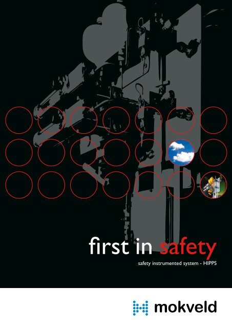
first in safety<br />
safety instrumented system - HIPPS
2<br />
Introduction to HIPPS<br />
HIPPS is an abbreviation of ‘High Integrity Pressure Protection System’. HIPPS are applied to prevent over-<br />
pressurisation of a plant by shutting-off the source of the high pressure. In traditional systems over-pressure is<br />
dealt with through relief of venting systems. These systems have obvious disadvantages such as release of<br />
(flammable and toxic) process fluids in the environment and often a large footprint of the installation. With the<br />
increasing environmental awareness relief systems are no longer an acceptable solution.<br />
HIPPS provides a technically sound and economically attractive solution to protect equipment in cases where:<br />
• High-pressures and / or flow rates are processed<br />
• The environment is to be protected.<br />
• The economic viability of a development needs improvement<br />
• The risk profile of the plant must be reduced<br />
What is HIPPS?<br />
HIPPS is an instrumented safety system that is designed and built in accordance with the IEC 61508 and IEC 61511<br />
standards. These international standards refer to safety functions and Safety Instrumented Systems (SIS) when discussing<br />
a device to protect equipment, personnel and environment.<br />
Older standards use terms like safety shut-down systems, emergency shut-down systems or last layers of defence.<br />
A system that closes the source of over-pressure within 2 seconds with at least the same reliability as a safety relief<br />
valve is usually called a HIPPS.<br />
A High Integrity Pressure Protection System is a complete functional loop consisting of:<br />
• The initiators that detect the high pressure. These initiators may be electronic or mechanical<br />
• For electronic HIPPS a logic solver, which processes the input from the initiators to an output to the final element<br />
• The final elements, that actually perform the corrective actions in the field by bringing the process to a safe state.<br />
The final element consists of a valve + actuator and possibly solenoids or mechanical initiators.<br />
Flaring of hydrocarbons causes damage to the<br />
environment and the CO production is not in<br />
2<br />
line with the Kyoto Protocol.<br />
HIPPS prevent over-pressurization by shutting down the source of the high pressure.
Standards & Design Practices<br />
The ever-increasing flow rates in combination with<br />
the environmental constraints initiated the widespread<br />
and rapid acceptance in the last decades of<br />
HIPPS as the ultimate protection system.<br />
The International Electro technical Commission<br />
(lEC) introduced the lEC 61508 and the IEC 61511<br />
standards in 1998 and 2003. These are performance<br />
based, non-prescriptive, standards which provide a<br />
detailed framework and a life-cycle approach for the<br />
design, implementation and management of safety<br />
systems applicable to a variety of sectors with<br />
different levels of risk definition. These standards<br />
also apply to HIPPS.<br />
The IEC 61508 mainly focuses on Electrical/Electronic/Programmable Safety-related systems. However it also provides<br />
a framework for safety-related systems based on other technologies including mechanical systems. The IEC 61511 was<br />
introduced by the IEC specifically for designers, integrators and users of safety instrumented systems and covers the<br />
other parts of the safety loop (initiators and final elements) in greater in detail.<br />
COMMUNITY EMERGENCY RESPONSE<br />
Emergency broadcasting<br />
PLANT EMERGENCY RESPONSE<br />
Evacuation procedures<br />
MITIGATION<br />
Mechanical mitigation systems<br />
Safety instrumented systems (SIS / HIPPS)<br />
PREVENTION<br />
Mechanical protection system or HIPPS<br />
Process alarms with operator corrective action<br />
Safety instrumented systems (SIS / HIPPS)<br />
CONTROL and MONITORING<br />
Basic process control systems<br />
Monitoring systems (process alarms)<br />
Operator supervision<br />
PROCESS<br />
The basis for the design of safety instrumented system is the required Safety Integrity Level (SIL). The SIL is<br />
obtained during the risk analysis of the plant or process and represents the required risk reduction. The SIS shall meet<br />
the requirements of the applicable SIL level which ranges from 1 to 4. The IEC standards define the requirements<br />
for each SIL level for the lifecycle of the equipment, including design and maintenance. The SIL level also defines a<br />
required Probability of Failure on Demand (PFD) for the complete loop and architectural constraints for the loop<br />
and it’s different elements.<br />
In practice the required protection level for HIPPS in Oil and Gas applications is often SIL3. But this is not cast<br />
in stone and should always be the result of a Hazard and Operability study (HAZOP). The requirements of the<br />
HIPPS should not be simplified to a PFD level only, the qualitative requirements and architectural constraints<br />
form an integral part of the requirements to an instrumented protection system such as HIPPS.<br />
A typical HIPPS safety loop consisting of 2oo3 initiators (Pressure Transmitters),<br />
a logic solver and 2 final elements being valve and actuator.<br />
3
4<br />
The European standard EN 12186 (DIN G491) and more specific the EN 14382 (DIN 3381) has been used for many<br />
years in (mechanically) instrumented overpressure protection systems. These standards prescribe the requirements<br />
for the over-pressure protection systems, and their components, in gas plants. Not only the response time and<br />
accuracy of the loop but also safety factors for over-sizing of the actuator of the final element are dictated by these<br />
standards. Independent design verification and testing to prove compliance to the EN 14382 standard is mandatory.<br />
Therefore users often refer to this standard for HIPPS design. The German DVGW certified the Mokveld final<br />
element including a mechanical initiator in 1974 in accordance with DIN 3381 (now EN 14382). Since that date<br />
Mokveld has field experience with safety shut-off loops (valves + actuator + initiator) closing within 2 seconds.<br />
Reliability<br />
Mokveld’s vast experience in fast stroking final elements totals over of 19 000 operational years (with more than 1000<br />
valves). The Mokveld final elements (a functional unit consisting of valve + actuator and possibly solenoids or mechanical<br />
initiators) are therefore proven-in-use for high reliability safety applications in natural gas and 2-phase hydrocarbons. Third<br />
parties, like the German TÜV and Atomic Energy Agency, have validated the Mokveld database and the derived reliability<br />
data, this includes failure rates for clean and unclean fluids.<br />
The certified Mokveld failure rate for the final element (being the valve + actuator) for a failure to deliver a full stroke<br />
in 2 seconds for applications in untreated hydrocarbons is: λ = 2,98 x 10⁻⁴ / year. The failure rate for the Mokveld<br />
hydraulic mechanical initiator mounted on the final element is: λ = 7,72 x 10⁻⁴ / year. This data enables Mokveld to<br />
supply a HIPPS to suit SIL 3 or even SIL 4 with a proof test interval of 1 year or a system fully in accordance with<br />
EN 12186 or EN 14382.<br />
The Mokveld final elements do not require additional electronic systems, like partial stroke testing device, to meet<br />
SIL 3 with a 1 year test interval. A separate technical datasheet on this subject is available.<br />
Two types of HIPPS<br />
SIL Safety Integrity Level PFD Probability of Failure on demand<br />
4 ≥10-5 to < 10-4 3 ≥10-4 to < 10-3 2 ≥10-3 to < 10-2 1 ≥10-2 to < 10-1 The corresponding PFD to each SIL. The required redundancy is not shown here.<br />
Based on our vast experience and expertise Mokveld offers two types of HIPPS<br />
1. Integral mechanical HIPPS, since 1974<br />
2. Full electronic HIPPS, since 2000
An example of how and where HIPPS can be implemented in, typical production facility.<br />
Initiators<br />
HIPPS with two Mokveld mechanical initiators<br />
protecting Shell Tutong metering station in Brunei.<br />
PIC<br />
The initiators detect the high pressure (or high level, or temperature). For the mechanical HIPPS this will be<br />
Mokveld’s mechanical initiators. For the electronic HIPPS this will be safety related pressure transmitters. The safety<br />
loop may consist of one or more sensors to achieve the required safety level.<br />
The Mokveld mechanical initiators are certified to EN 14382 (DIN 3381) and have a setpoint accuracy better than 1%<br />
of the setpoint. For both the pneumatic and the hydraulic version third party validated reliability data are available.<br />
The safety systems based on these initiators are easily identifiable in the plant, easy to operate and relatively<br />
simple. This makes it inherently safe systems. As an option a full stand-alone system requiring no external energy is<br />
available for applications in remote areas.<br />
Example of a HIPPS consisting of 2 final elements each having two mechanical initiators, SIL 4<br />
is obtained. Testing can be done via the high integrity manifold block with key interlock system.<br />
5
6<br />
Logic Solver<br />
The Logic Solver processes the signals from the initiators (pressure transmitters) and closes the final element for<br />
instance by de-energising the solenoids. A system based on mechanical initiators does not require a separate logic<br />
solver. A SIS or HIPPS utilising pressure transmitters and a logic solver are typically used when remote sensing is<br />
required. Usually 3 pressure transmitters are used and the Logic Solver de-energises the solenoids when 2 give a high<br />
signal (2 out of 3 voting). The logic solver is probably<br />
the most complex device in the loop, especially the<br />
programmable ones. At present many are available<br />
with certificates showing suitability in SIL 3 safety loops.<br />
In general Mokveld uses hard-wired solid-state logic<br />
solvers based on the magnetic core technology. These<br />
systems are inherently fail-safe and are therefore<br />
certified for applications in SIL 4 loops.<br />
Final Element<br />
The IEC 61508 does not give the final elements the<br />
attention they deserve, the IEC 61511 already has more<br />
focus on this part of the loop. Whereas this is specifically<br />
required for fast acting safety loops (requiring shut-off<br />
within 2 seconds) in a low demand mode. The EN 12186<br />
recognises this and refers to the EN 14382 for the design<br />
of the final element.<br />
Slam-shut valves in HIPPS applications usually have long<br />
periods of inactivity (valve remains fully open for a long<br />
period). The design shall be such that this does not<br />
influence the response time of the valve, nor the<br />
stroking speed once a demand occurs. A regular partial<br />
stroking cycle is not a solution as this may result in<br />
a partial closure upon a demand as well.<br />
Typical logic solver panel. Mokveld engineering assistance will provide a fault tree analysis of your system<br />
during proposal stage.
The following features make the Mokveld axial on-off valve inherently safe and suitable for HIPPS applications:<br />
a) The break-away thrust is minimal, even after long periods of inactivity.<br />
b) Erosion and subsequent degradation into leak tightness is avoided.<br />
c) The required actuator thrust is low and independent of the pressure differential across the valve.<br />
d) Very short stroking times (e.g. 2 seconds for 24 inch valves) are possible due to the low mass of the moving parts.<br />
e) The piston does not slam onto the seat but slides into the seat.<br />
f) The integrated design of valve and actuator assures that the thrust safety margin is sufficient at all times.<br />
Please refer to the Mokveld axial on-off valve brochure for more detailed explanation of the specific benefits.<br />
Mokveld can assist in defining the response time of your system in the proposal stage.<br />
Mokveld Engineering Assistance<br />
Mokveld engineers can provide support in an early phase of the project. We can assist in defining suitable HIPPS<br />
architecture, fault tree analysis, determining the pressure rise in the protected volume and the required stroking<br />
times and set points of the entire system.<br />
For further<br />
information<br />
contact:<br />
Mokveld Valves BV<br />
www.mokveld.com<br />
Copyright<br />
© Mokveld Valves,<br />
The Netherlands.<br />
February 2011<br />
7
global network - supported locally<br />
Mokveld Offices<br />
1 Mokveld Valves BV<br />
2 Mokveld USA Inc<br />
3 Mokveld UK Ltd<br />
4 Mokveld Norge AS<br />
5 Mokveld Central Europe GmbH<br />
6 Mokveld Marketing JV<br />
7 Mokveld Valves BV, Middle East<br />
8 Mokveld Valves BV, Saudi Arabia<br />
9 Mokveld Valves BV, Asia Pacific<br />
10 Mokveld Valves BV, China<br />
11 Mokveld Valves BV, Algeria<br />
2<br />
Mokveld Valves BV • Nijverheidsstraat 67 • PO Box 227 • NL-2800 AE Gouda • The Netherlands<br />
T +31 182 59 75 00 • F +31 182 51 79 77 • E info@mokveld.com • I www.mokveld.com<br />
3<br />
4<br />
1<br />
5<br />
11<br />
6<br />
8<br />
7<br />
Adresses<br />
Gouda, The Netherlands<br />
Houston (Tx), United States of America<br />
Cirencester, United Kingdom<br />
Stavanger, Norway<br />
Oberhausen, Germany<br />
Sumy, Ukraine<br />
Dubai, United Arab Emirates<br />
Al Khobar, Saudi Arabia<br />
Kuala Lumpur, Malaysia<br />
Beijing, the People’s Republic of China<br />
Alger, Algeria<br />
9<br />
10<br />
E-mail<br />
info@mokveld.com<br />
usa@mokveld.com<br />
uk@mokveld.com<br />
norge@mokveld.com<br />
central.europe@mokveld.com<br />
mokveld.marketing@mokveld.com<br />
mideast@mokveld.com<br />
saudi.arabia@mokveld.com<br />
asiapacific@mokveld.com<br />
china@mokveld.com<br />
algeria@mokveld.com<br />
AL0211HPS