Catalogo caldaie HOVAL - Certificazione energetica edifici
Catalogo caldaie HOVAL - Certificazione energetica edifici
Catalogo caldaie HOVAL - Certificazione energetica edifici
- No tags were found...

Create successful ePaper yourself
Turn your PDF publications into a flip-book with our unique Google optimized e-Paper software.
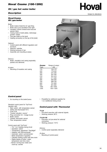
Hoval Cosmo (100-1200)PriceSubject to alterationsCosmoOil /gas hot water boilerBoilerBoiler made of steel for oil/gas firing withoutcontrol panelPart no.DeliveryBoiler, insulation and casing separately packedand delivered.Cosmo Range of output Working pressureType kW bar175 100-175 6240 176-240 6290 241-290 6350 291-350 6410 351-410 6465 411-465 6585 466-585 6700 586-700 6850 701-850 6950 851-950 61050 951-1050 61200 1051-1200 6Delivery:Assembly and mounting at place.Cosmo Range of output Working pressureType kW bar175 100-175 6240 176-240 6290 241-290 6350 291-350 6410 351-410 6465 411-465 6585 466-585 6700 586-700 6850 701-850 6950 851-950 61050 951-1050 61200 1051-1200 685
Hoval Cosmo (100-1200)PriceSubject to alterationsControl panel with TopTronicregulator for Cosmo and 1 to 4mixing circuitsStandard control panel:DeliveryControl panel separately packed anddeliveredPart no.Regulator set:M3.1For external on/off and nominal/maximumoutput control with TopTronic or otherregulator. Boiler temperature sensor KT10 forregulation already integrated.– With 7- + 4-pin plug connection for burnercontrol1H01031TopTronic 223B1 stage burner controlRegulation of 1 mixing circuit, 1 direct heatingcircuit without mixing valve and hot water loadingcircuit, incl. sensors.691494TopTronic 203BModulating burner controlRegulation of 1 mixing circuit, 1 direct heatingcircuit without mixing valve and hot water loadingcircuit, incl. sensors 691493TopTronic 2233B2 stage burner controlRegulation of 2 mixing circuit, 1 direct heatingcircuit without mixing valve and hot water loadingcircuit, incl. sensors691435Additional Regulators:TopTronic 3for 1 additonal mixing circuit, including sensors 691335KV....flowKR....return86
Hoval Cosmo (100-1200)PriceSubject to alterationsPart no.TopTronic 233Bfor 2 additional mixing circuit, including sensors691282KV....flowKR....returnAdditonal equipment ZM1Adapter set for second regulator691138Thermostat control panel(boiler control without heatingregulator)T 2.2 (Pre-wired solution)- for systems without TopTronic regulator- for direct 2 stage burner control- For external calorifier or external heatingcommandsNot usable for:- Boiler sequence control- Dual fuel burner- consists of:- Main switch 0/1- Switch summer/winter- Switch burner output- Boilerlimit thermostat 110°C- 3 boiler thermostat 50-110°C- Trouble indication boiler/burner- 7+4-pin burner plug connection- 2 burner running hour meter- 2 burner running hour meter and count upcounter- Flue gas thermometer1H01030AU2970AU3268AU3351T0.2-110 (for external control)- for systems without TopTronic regulator- for boiler sequence control- for special control functionsconsists of:- Main switch 0/1- Boiler limit thermostat 130°C- 3 boiler thermostat 50-110°C- without burner plug connection- 2 burner running hour meter- 2 burner running hour meter and count upcounter- Flue gas thermometer- Additional sensor for external TopTronicregulator1H01029AU3323AU3324AU3351600139687
Hoval Cosmo (100-1200)PriceSubject to alterationsAccessories for heating controlsystem TopTronicRoom station RS 10for one mixing circuit with room sensor,information, program and correction keyPart no.242634Remote control RFF 60Sfor one mixing circuit with room sensor, easyprogram switch, temperature adjustment2000754Room temperature sensor RF 40for one mixing circuit (instead of RS10 orRFF60S)Additional outdoor temperaturesensorAF 100Nfor one mixing circuit (per heating circuit1 separate outdoor temperature sensor ispossible)242679242646Flue gas temperature sensor PT1000/4 242681Temperature sensor KT 10-40with 4 m cabel for calorifier or external heataquisition 242371Temperature Sensor VF100Nfor min. return flow temperature for systemswith boiler curcuit pump. 242647Flow temperature safety thermostatfor floor heating(per heating circuit 1 thermostat)- Thermostat with pocket 619.0015- Thermostat 692.1120242190242217Flow temperature Sensor9C2.70301for floor heating incl. cable and plug 687997Resistor 910 Ohm 200260288
Hoval Cosmo (100-1200)PriceSubject to alterationsServicePart no.Commission89
Hoval Cosmo (100-1200)Technical dataSubject to alterationsCosmoType 175 240 290 350 410 465 585 700• Nominal output kW 1 175 240 290 350 410 465 585 700• Minimum output kW 100 145 155 165 190 205 220 260• Maximum burner output kW 190 262 317 382 448 508 639 765• Max. boiler operation temperature °C 90 110 110 110 110 110 110 110• Limit thermostat °C 130 130 130 130 130 130 130 130• Min. flue gas temperature 3 °C 130 130 130 130 130 130 130 130• Min. operation temperature 3 °C 60 60 60 60 60 60 60 60• Min. return flow temperature 3 °C 55 55 55 55 55 55 55 55• Working / Test pressure bar 6/9 6/9 6/9 6/9 6/9 6/9 6/9 6/9• Boiler efficiency at 80/60°C % 92,8 93,2 93,0 93,3 93,1 93,0 93,0 92,9• Stand-by losses qB at 70°C Watt 660 678 695 822 971 1023 1079 1112• Flue gas resitsance at nominal output180°C flue gas temperature, 12.5% CO 2,500 m above sea level (+/- 20%) mbar 1,0 1,0 1,3 2,0 2,0 2,2 2,8 3,2• Flow resistance 2 z-value 0,1 0,072 0,068 0,030 0,030 0,033 0,033 0,009• Water content Litre 270 333 385 396 455 574 617 697• Weight (incl. casing) kg 577 640 695 801 862 932 1184 1273• Fire room dimensionØ-inside x Length mm 490x984 490x1234 490x1434 558x1248 558x1448 558x1648 686x1457 686x1657• Fire room volume m³ 0,18 0,23 0,26 0,33 0,38 0,44 0,52 0,60• Dimension width mm 970 970 970 1078 1078 1078 1226 1226length mm 1614 1864 2064 1864 2064 2264 2105 2305height mm 1102 1102 1102 1120 1120 1120 1403 14031kW= Flue gas deficiency according to LRV 92 (Boiler water 80°C)2Flow resitsance boiler in mbar = volume flow (m 3 /h) 2 x z3At min. output, oil and gas 60% of max. output90
Hoval Cosmo (100-1200)Technical dataSubject to alterationsCosmoType 850 950 1050 1200• Nominal output kW 1 850 950 1050 1200• Minimum output kW 350 460 480 570• Maximum burner output kW 929 1038 1148 1311• Max. boiler working temperature °C 110 110 110 110• Limit thermostat °C 130 130 130 130• Min. flue gas temperature 3 °C 130 130 130 130• Min. operation temperature 3 °C 60 60 60 60• Min. return flow temperature 3 °C 55 55 55 55• Working / Test pressure bar 6/9 6/9 6/9 6/9• Boiler efficiency at 80/60°C % 91,4 91,5 91,6 91,5• Stand-by deficiency qB at 70°C Watt 1281 1495 1571 1850• Flue gas resitsance at nominal output180°C flue gas temperature, 12.5% CO 2,500 m above sea level (+/- 20%) mbar 3,8 4,0 4,5 5,2• Flow resistance 2 z-value 0,008 0,005 0,005 0,005• Boiler water capacity Litre 837 1134 1134 1138• Weight (incl. casing) kg 1433 1792 1792 2004• Fire room dimensionØ-inside x Length mm 686x2007 834x1877 834x1877 837x2227• Fire room volume m³ 0,72 0,99 0,99 1,18• Dimension width mm 1226 1400 1400 1400length mm 2655 2504 2504 2854height mm 1403 1580 1580 15801kW= Flue gas deficiency according to LRV 92 (Boiler water 80°C)2Flow resitsance boiler in mbar = volume flow (m 3 /h) 2 x z3At min. output, oil and gas 60% of max. output91
Hoval Cosmo (100-1200)DimensionSubject to alterationsCosmo(Measurements in mm)1 Flow2 Return3 Safety valve4 Drain R11/2“ (175-465)6 Flue gas monitoring pointR 1/2“ (plugged off)7 Cleaning door8 Smokebox drain R1/2“9 Control panel10 Optional TopTronic controller(s)CosmoType A B C D E F G H J K L M N175 970 1014 1033 955 920 1102 495 1145 1614 552 552 201 110240 970 1264 1033 1055 920 1102 495 1295 1864 552 552 201 110290 970 1464 1033 1000 920 1102 495 1495 2064 552 552 201 110350 1078 1264 1141 1105 1028 1210 515 1365 1864 606 606 201 110410 1078 1464 1141 1185 1028 1210 515 1465 2064 606 606 201 110465 1078 1664 1141 1100 1028 1210 515 1665 2264 606 606 201 110585 1226 1464 1334 1245 1176 1403 565 1515 2105 725 725 231 110700 1226 1664 1334 1360 1176 1403 565 1665 2305 715 715 231 110850 1226 2014 1334 1245 1176 1403 565 2015 2655 725 725 231 110950 1400 1864 1491 1355 1350 1580 595 1845 2504 795 795 231 801050 1400 1864 1491 1355 1350 1580 595 1845 2504 795 795 231 801200 1400 2214 1491 1515 1350 1580 595 2195 2854 795 795 231 8092
Hoval Cosmo (100-1200)Dimensions / burner mountingSubject to alterationsCosmo (175 - 1200)Flange Cosmo 175 - 465 Flange Cosmo 585 - 1200Dimension(all measurements in mm)Cosmo A B C D E F G Hmin max175 270 320 490 984 230 350 160 200 M12240 270 320 490 1234 230 350 200 200 M12290 270 320 490 1434 230 360 200 200 M12350 270 440 588 1248 350 460 200 250 M12410 270 440 558 1448 350 460 250 250 M12465 270 440 558 1648 350 460 250 250 M12585 300 500 686 1457 350 460 250 250 M12700 300 500 686 1657 350 460 250 250 M12850 300 500 686 2007 350 460 250 250 M12950 300 500 834 1877 350 460 250 250 M121050 300 500 834 1877 350 460 250 250 M121200 300 500 834 2227 350 460 250 250 M1293
Hoval Cosmo (100-1200)Flue gas / Output diagramSubject to alterationsFlue gas / Output diagram2001753507009501050 12501802404105 858 502904 65160140120100 300 500 700 900 1100kWkW = Boiler output°C = Flue gas temperature with Oil EL, Flow 80°C, Return flow 60°C, CO 2Heizöl EL = 13,0%, clean heating surfaceFiring with gas or oil L if the flue gas temperature is approx. 15°C higher94
Hoval Cosmo (100-1200)EngineeringSubject to alterationsStandards and guidelines Heating armature groupThe following standards and guidelines must be - Min. volume of mixing valve:complied with:H4G-1½’’ = 1,5 m³/h,- Hoval technical information and installation H4G 2’’ = 2,2 m³/h.instructions- Hydraulic and technical control regulations ofthe local gas supply authority- Gas directives G1 of the SVGW- Flue gas systemes are to be createdaccording to the SVGW directives and theVKF fire protection guidelines.- Local fire brigade regulations- The fire protection regulations of the VKF- Procal data sheet „Corrosion through halogen compounds“- Procal data sheet „ Corrosion damage inheating installations“ and the brochure„Protection against corrosion and boilerscale formation in heating and service waterinstallations“- Ventilation and air supply for the boilerinstallation room according to directivesSWIKI 91-1- Directives SWKI 97-1 «Water treatment forheating, steam and air conditioninginstallations»- Approval for diverting the flue gascondensate water to the drainage systemmust be obtaines from the responsibleauthority- Heating waterpH-value 8,3 to 9,0max. oxygen content 0,1 mg/m 3chlorine content max. 30 mg/m 3Water treatment- Old installations must be well flushed beforefilling.- The water quality must be tested at leastonce a yearOil burner mounting- The burner connection plug must bemounted opposite the burner door hinges.- It should be possible to swivel the boilerdoor incl. burner by 90°.- The space between burner and boiler doormust be insulated by the additional deliveredinsulation materialElectric connection of the burner- 1 x 230 V, 50 Hz, 10 A.- For safety reasons the electric cable ofthe burner must be that short that the plugmust be removed when swivelling boilerdoor.Sound absorbationSound absorbation is possible through thefollowing steps:- Walls, ceilings and floor should be verysolidly built, a sound absorber should bemounted into the air inlet. Pipe holders andsupport should be protected by means ofanti-vibration sleeves.- Install sound absorber hood for burner.- If living rooms are located above or underthe boiler room, vibration absorbers have tobe mounted to the boiler base. Pipes andflue gas tube must be connected flexiblewith compensators.- Pumps have to be connected withcompensators to the pipes.- For damping of flame noise it is possible toinstall a silencer into the flue gas tube(Space should be foreseen for laterinstallation).foreseen.Chimney- The chimney must be water proof, acidresistant and suitable for flue gastemperature > 160°C- For existing chimney installation therestoration must be carried out accordingto the instructions of the chimneyconstructor.- The cross sections are to be calculated forboilers without draft requirementsD< 2D2 x D 1DSanitary installation- The installation must be carried outaccording to the regulation of local waterworks.- Pressure safety limit max 8 bar.DHeating systemCombustion Air- The combustion air supply must bewarranted. Opening must not be lockable.- Minimal free cross section for air opening6.5 cm2 per 1 kW boiler output.Insulation and Casing- To mount the insulation and casing you needabout 40 cm space on the left and right side.After the boiler is cased no space on the sideis required.- 2 boiler can be placed without spacebetween them. (The door of the left boilermust swivelling to the left and the the rightdoor to the right).Chimney / Flue gas systemFlue gas tube- The flue gas tube must be led into thechimney with an angle of 30-45 °.- If the flue gas tube is longer than 1m, itmust be insulated.- The inlet of the flue gas tube into thechimney has to be carried out in such way,that no condensate can flow from thechimney into the flue gas tube and boiler- A closeable flue gas measuring socket withan inner diameter of 10-21 mm must be95
Hoval Cosmo (100-1200)Assembly and mounting on siteSubject to alterationsAssembly and mounting onsite Cosmo (100-1200)At a favourable all inclusive price Hoval offerson-site assembly of boiler in complete ofcomponent form as well as mounting in boilerroom ready to be connected. Mountingaccording to the strict quality standards of theassembly department.• In case of an order, please add in yourorder „assembly and mounting on site“• Assembly and mounting work on site hasto be coordinate with Hoval on a case tocase basiscdeabCombustion chamberWater wall shellCosmoweighttype a b kg175 500 943 59240 500 1193 74290 500 1393 86350 600 1325 112410 600 1525 130465 600 1725 148585 700 1434 185700 700 1734 210850 700 2084 250950 850 1948 3161050 850 1948 3161200 850 2298 375Cosmoweighttype c d e kg175 988 802 401 40240 1238 802 401 50290 1438 802 401 58350 1238 910 455 59410 1438 910 455 65465 1538 910 455 74585 1436 1056 528 74700 1636 1056 528 84850 1986 1056 528 102950 1834 1270 635 1141050 1834 1270 635 1141200 2184 1270 635 13696
Hoval Cosmo (100-1200)Assembly and mounting on siteSubject to alterationsPlace requirement for assembly and mounting on siteMin. Heating room dimension in mm175 240 290 350 410 465 585 700 850 950 1050 1200Length 3000 3000 3000 3000 3000 3000 3500 3500 3500 4000 4000 4000Width 2200 2200 2200 2200 2200 2200 2500 2500 2500 2800 2800 2800Hight 2500 2500 2500 2500 2500 2500 3000 3000 3000 3000 3000 3000.97
Hoval Max-3 (250-1250)Oil / gas hot water boilerDescriptionsubject to alterationsHoval Max-3Oil / gas hot water boilerBoiler• 3-pass steel boiler for oil / gas firing• Boiler door to be swivelled to the right or left• Insulation 80mm mineral wool mat andspecial fabric• Casing made of steel plates, red/orangepowder coated• Flue gas outlet and heating returnconnections on the back, heating flowconnection on the topOptional• Control panel with different regulators andfunctions• Calorifier• Assembly and Mounting at placeDelivery• Boiler, insulation and casing separatelypacked and delivered.At place• Mounting of insulation and casingMax-3 Range of outputTypekW250 160-300320 192-360420 252-500530 318-610620 372-720750 450-8701000 600-11501250 750-1400Control panel• for mounting on the boiler Max-3Standard boiler control panel for TopTronicregulator with:• Main switch, with temperature guard• Safety limit thermostat 110°C• Fuse 6.3A• Trouble indication „burner“• Plug connection for 2-stage burner• Boiler sensor• Outdoor temperature sensor• flow temperature sensorControl panel with TopTronic heating regulator– for 1 or 2 heating circuit– Operation switch– Temperature adjustment “Day/Night”– Adaption with Microcomputer– Automatic switch summer/winter– Heating boiler temperature control– Calorifier loading control with time clock– Digital display of boiler- / watertemperature and time clock– Burner running hour meter and count-upcounterControl panel with ThermostatT 2.2• Pre-wired execution with external signals• Working pressure 90°CT 0.2-110• Execution not pre-wired for externalconnection• Working pressure 110°CDelivery• Control panel separately deliveredAt place• Mounting of control panel• Possibility for additional regulator for 1 or 2additional mixing circuit84
Hoval Max-3 (250-1250)Pricesubject to alterationsMax-3Oil/gas hot water boilerPart no.Hot water boiler3-pass steel hot water boiler for oil/gas firingwithout control panelDelivery: completeBoiler, insulation and casing separately packedand delivered.Max-3 Range of output Working pressureType kW bar250 160-300 6 1A16021320 192-360 6 1A16022420 252-500 6 1A16023530 318-610 6 1A16024620 372-720 6 1A16025750 450-870 6 1A160261000 600-1150 6 1A160271250 750-1400 6 1A16028Delivery: welding on-siteAssembly and mounting at place.Max-3 Range of output Working pressureType kW bar320 PGS 192-360 6 1A 16030420 PGS 252-500 6 1A 16031530 PGS 318-610 6 1A 16032620 PGS 372-750 6 1A 16033750 PGS 450-870 6 1A 160341000 PGS 600-1150 6 1A 160351250 PGS 750-1400 6 1A 16036Boiler Max-3 250 is not as „assembly andmounting on-site boiler“ available.85
Hoval Max-3 (250-1250)Pricesubject to alterationsControl panel with TopTronicregulator for Max-3 for 1 to 4mixing circuitsStandard control panel:DeliveryControl panel separately packed anddeliveredPart no.Regulator set:M3.1For external on/off and nominal/maximumoutput control with TopTronic or otherregulator. Boiler temperature sensor KT10 forregulation already integrated.– With 7- + 4-pin plug connection for burnercontrol1H01031TopTronic 223B1 stage burner controlRegulation of 1 mixing circuit, 1 direct heatingcircuit without mixing valve and hot water loadingcircuit, incl. sensors.691494TopTronic 203BModulated burner controlRegulation of 1 mixing circuit, 1 direct heatingcircuit without mixing valve and hot water loadingcircuit, incl. sensors 691493TopTronic 2233B2 stage burner controlRegulation of 2 mixing circuit, 1 direct heatingcircuit without mixing valve and hot water loadingcircuit, incl. sensors691435Additional Regulators:TopTronic 3for 1 additonal mixing circuit, including sensors 691335KV....flowKR....return86
Hoval Max-3 (250-1250)Pricesubject to alterationsPart no.TopTronic 233Bfor 2 additional mixing circuit, including sensors691282KV....flowKR....returnAdditonal equipment ZM1Adapter set for second regulator691138Boiler control without heatingregulatorThermostat control panel(optional to standard controlpanel with regulator)T 2.2 (Pre-wired solution)- for systems without TopTronic regulator- for direct 2 stage burner control- For external calorifier or external heatingcommands1H01030Not usable for:- Boiler sequence control- Dual fuel burner- consists of:- Main switch 0/1- Switch summer/winter- Switch burner load- Boiler limit thermostat 110°C- 3 boiler thermostat 50-110°C- Trouble indication boiler/burner- 7+4-pin burner plug connection- 2 burner running hour meter- 2 burner running hour meter and count upcounter- Flue gas thermometerAU2970AU3268AU3351T0.2-110 (for external control)- for systems without TopTronic regulator- for boiler sequence control- for special control functions1H01029consists of:- Main switch 0/1- Boiler limit thermostat 130°C- 3 boiler boiler thermostat 50-110°C- without burner plug connection- 2 burner running hour meter- 2 burner running hour meter and count upcounter- Flue gas thermometer- Additional sensor for external TopTronicregulatorAU3323AU3324AU3351600139687
Hoval Max-3 (250-1250)Pricesubject to alterationsAccessories for heating controlsystem TopTronicPart no.Room station RS 10for one mixing circuit with room sensor,information, program and correction key 242634Remote control RFF 60Sfor one mixing circuit with room sensor, easyprogram switch and temperature adjustment 2000754Room temperature sensor RF 40for one mixing circuit (instead of RS10 orRFF60S)Additional outdoor temperaturesensorAF 100Nfor one mixing circuit (per heating circuit1 separate outdoor temperature sensor ispossible)242679242646Flue gas temperature sensor PT1000/4 242681Temperature sensor KT 10-40with 4 m cabel for calorifier or external heataquisition 242371Temperature Sensor VF100Nfor min. return flow temperature for systemswith boiler curcuit pump. 242647Flow temperature safety thermostatfor floor heating(per heating circuit 1 thermostat)- Thermostat with pocket 619.0015- Thermostat 692.1120242190242217Flow temperature Sensor9C2.70301for floor heating incl. cable and plug 687997Resistor 910 Ohm 200260288
Hoval Max-3 (250-1250)Pricesubject to alterationsAccessoriesPart no.Vibration damper for boiler baseFor sound and vibration absorbation. Made ofunvulcanized rubber.Cross section 80/50mm.Delivery4 vibration damper per boiler, mounted underthe boiler baseTo Max-3LengthType Size mm250-530 3 200 239706620-750 L400 400 2397081000-1250 L500 500 239709Flue gas thermometerØ 80–150 (Mounting at place) 24113389
Hoval Max-3 (250-1250)Pricesubject to alterationsServicePart no.Commissioning90
Hoval Max-3 (250-1250)Technical datasubject to alterationsMax-3Type 250 320 420 530 620 750 1000 1250• Max. output kW 1 300 360 500 610 720 870 1150 1400• Min. output kW 160 192 252 318 372 450 600 750• Max. buner output kW 323 388 535 665 773 933 1234 1514• Max. Boiler working temperature °C 120 120 120 120 120 120 120 120• Safety limit temperature °C 130 130 130 130 130 130 130 130• Min. Flue gas temperature oil/gas 3 °C 130 130 130 130 130 130 130 130• Min. boiler flow temperature oil/gas 3 °C 60/65 60/65 60/65 60/65 60/65 60/65 60/65 60/65• Min. return temperature oil/gas 3 °C 50/55 50/55 50/55 50/55 50/55 50/55 50/55 50/55• Working / Test pressure bar 6/9 6/9 6/9 6/9 6/9 6/9 6/9 6/9• Boiler efficiency at 80/60°C % 92,3 93,2 92,9 92,6 92,5 92,5 92,6 92,6• Stand-by deficiency qB at 70°C Watt 680 819 1000 1035 1120 1180 1250 1380• Flue gas resistance at nominal output180°C flue gas temperature, 12.5% CO 2,500 m above sea level (+/- 20%) mbar 2,54 4,5 4,9 5,7 5,2 6,5 7,4 9,0• Flue gas volume at nominal output12,5% Co 2Oil kg/h 520 554 850 1037 1224 1479 1955 2295• Flow resistance boiler 2 z-value 0,1 0,1 0,022 0,022 0,008 0,008 0,003 0,003• Water flow resistance at 15K mbar 29,4 33,4 18,0 26,7 13,5 19,8 13,0 17,920K mbar 16,5 18,8 10,1 15,0 7,6 11,1 7,3 10,8• Water flow volume at 15K m 3 /h 17,14 18,20 28,57 34,86 41,14 49,71 65,71 77,1420K m 3 /h 12,86 13,71 21,43 26,14 30,86 37,29 49,29 57,86• Boiler content Liter 361 420 552 520 969 938 1528 1478• Boiler gas volume m³ 0,317 0,370 0,583 0,602 0,846 0,872 1,350 1,390• Insulation boiler body mm 80 80 80 80 80 80 80 80• Weight (incl. casing) kg 793 885 1093 1150 1770 1800 2500 2600• Weight (without casing) kg 693 765 943 1000 1590 1620 2360 2460• Fire room dimensionØ-inside x Length mm 486x1295 486/1515 606/1624 606/1624 684/1899 684/1899 782/2182 782/2182• Fire room volume m³ 0,240 0,282 0,466 0,466 0,669 0,669 1,047 1,047• Dimension width mm 970 970 1190 1190 1310 1310 1500 1500(without burner and length mm 1736 2065 2178 2178 2452 2452 2739 2739sound absorber hood) height mm 1255 1255 1435 1435 1555 1555 1755 17551kW= Flue gas deficiency according to LRV 92 (Boiler water 80°C)2Boiler water flow resistance in mbar = water flow volume (m 3 /h) 2 x z3At min. output, oil and gas 60% of max. output91
Hoval Max-3 (250-1250)Dimensionsubject to alterationsMax-3(Measurements in mm)b3kln1m8ohh1ipc926810aqfl1g7vo345w2t u6sr1 Flow (250-320) DN 65(420-530) DN 100(620-750) DN 125(1000-1250) DN 1502 Return (250-320) DN 65(420-530) DN 100(620-750) DN 125(1000-1250) DN 1503 Flue gas outlet4 Cleaning opening5 Flue gas collector - cleaning opening R1"6 Drain R1 1/2"7 Cable connection8 Control panel9 Electric connection10 Socket Rp 3/4" with pocket forboiler temperature sensorMax-3Type a b c f g h h1 i k l l1 m n Ø o p q r s t u v w250 850 970 450 1440 178 1255 1050 800 109 1845 1736 579 93 249 59 39 170 420 527 592 1143 345320 850 970 450 1660 178 1255 1050 800 109 2065 1956 579 93 249 59 39 170 420 527 592 1143 345420-530 1060 1190 515 1770 181 1435 1230 950 104 2178 2074 641 100 299 54 34 175 350 595 660 1330 450620-750 1180 1310 550 2045 181 1555 1350 1050 105 2452 2347 666 95 349 55 35 170 550 722 786 1445 4751000-1250 1370 1500 635 2330 181 1755 1549 1250 107 2739 2632 681 111 349 77 37 175 415 620 685 1660 59092
Hoval Max-3 (250-1250)Raw boiler dimensionsubject to alterationsDimension without insulation and casingBoiler incl. boiler door, outlet without flue gas collector.(Measurment in mm)ezdc1bhgw=ø innenkpls4n2ox100yirq3vvafm1 Flow2 Return3 Drain4 Flue gas outletMax-3Type a b c d e f g h i k l m n o p250 1589 149 1440 227 1889 850 1000 184 120 880 1184 1746 178 400 –320 1809 149 1660 227 2109 850 1000 184 120 880 1184 1966 178 400 –420-530 1920 150 1770 277 2222 1060 1180 196 120 1060 1376 2077 175 460 1072620-750 2195 150 2045 228 2498 1180 1300 196 120 1180 1496 2353 172 485 11921000-1250 2480 150 2330 228 2783 1370 1500 160 120 1380 1660 2638 198 500 1392Max-3Type q r s v w x y z 1 2 3 4250 170 420 800 370 812 1143 143 – DN 65/PN 6 DN 65/PN 6 1 1/2" Ø 249320 170 420 800 370 812 1143 143 – DN 65/PN 6 DN 65/PN 6 1 1/2" Ø 249420-530 175 350 950 475 990 1330 150 1140 DN 100/PN 6 DN 100/PN 6 1 1/2" Ø 299620-750 170 550 1050 535 1110 1445 145 1260 DN 125/PN 6 DN 125/PN 6 1 1/2" Ø 3491000-1250 175 415 1250 630 1298 1660 150 1450 DN 150/PN 6 DN 150/PN 6 1 1/2" Ø 349Required min. door and corridormeasurment for boiler movement(min. calculated measurements)K =BTx LT =BKx LT = Door widthK = Corridor widthB = Boiler widthL = Max. boiler lengthKLB< 150T93
Hoval Max-3 (250-1250)Combustion related dimensionsubject to alterationsMax-3 (250-320) Max-3 (420-530)Max-3 (620-1250)AAADDDCBCBCB60˚15˚45˚45˚15˚Flange Max-3 (250-320)4 x M10 (45°)FFlange Max-3 (420–530)4 x M12 (45°) +4 x M12 (15°)Flange Max-3 (620–750)6 x M12 (15°)Flange Max-3 (1000–1250)6 x M16 (15°)EGHDimensionMax-3Type A B C D E F G H250 240 270 450 195 486 1295 162 30320 240 270 450 195 486 1515 162 30420-530 290 330 515 250 606 1624 163 30620-750 350 400 550 310 684 1899 163 301000-1250 400 450 635 330 782 2182 163 30(All measurement in mm)94
Hoval Max-3 (250-1250)Flue gas / Output diagramsubject to alterationsFlue gas / Output diagramkW = Boiler output°C = Flue gas temperature with diesel oil, flow 80°C, return flow 60°C, CO 2diesel oil = 13,0%, clean heating surfaceFiring with gas or medium oil the flue gas temperature is approx. 15°C higherFlue gas resistancekW95
Hoval Max-3 (250-1250)Projetingsubject to alterationsStandards and guidelinesThe following standards and guidelines must beabserved:- Hoval technical information and installationinstructions- Hydraulic and technical control regulations ofthe local gas supply authority- Gas directives G1 of the SVGW- Flue gas systemes are to be createdaccording to the SVGW directives and theVKF fire protection guidelines.- Local fire brigade regulations- The fire protection regulations of the VKF- Procal data sheet „Corrosion through halogen compounds“- Procal data sheet „ Corrosion damage inheating installations“ and the brochure„Protection against corrosion and boilerscale formation in heating and service waterinstallations“- Ventilation and air supply for the boilerinstallation room according to directivesSWIKI 91-1Burner mounting- The burner connection plug must bemounted opposite the burner door hinges.- It should be possible to swivel the boilerdoor incl. burner by 90°.- The space between burner and boiler doormust be insulated by the additional deliveredinsulation materialElectric connection of the burner- 1 x 230 V, 50 Hz, 10 A. for control- 1 x 230V or 3x 400V for burner motor- For safety reasons the electric cable ofthe burner must be that short that the plugmust be removed when swivelling boilerdoor.Sound absorbationSound absorbation is possible through thefollowing steps:- Walls, ceilings and floor should besolid built, a sound absorber should bemounted into the air inlet. Pipe holders andsupport should be protected by means ofanti-vibration sleeves.Chimney- The chimney must be water proof, acidresistant and suitable for flue gastemperature > 160°C- For existing chimney installation therestoration must be carried out accordingto the instructions of the chimneyconstructor.- The cross sections are to be calculated forboilers without draft requirementsD< 2D2 x D 1DSanitary installation- The installation must be carried outaccording to the regulation of local waterworks.- Pressure safety limit max 6 bar.D- Directives SWKI 97-1 «Water treatment forheating, steam and air conditioninginstallations»- Approval for diverting the flue gascondensate water to the drainage systemmust be obtaines from the responsibleauthority- Heating water requirementtotal hardness less than 1°fpH-value 8,3 to 9,0max. oxygen content 0,1 mg/m 3chlorine content max. 30 mg/m 3Water treatment- Old installations must be well flushed beforefilling.- The water quality must be tested at leastonce a yearHeating systemCombustion Air- The combustion air supply must bewarranted. Opening must not be lockable.- Minimal free cross section for air opening6.5 cm2 per 1 kW boiler output.Insulation and Casing- To mount the insulation and casing you needabout 40 cm space on the left and right side.After the boiler is cased no space on the sideis required.- 2 boiler can be placed without spacebetween them. (The door of the left boilermust swivelling to the left and the the rightdoor to the right).- Install sound absorber hood for burner.- If living rooms are located above or underthe boiler room, vibration absorbers have tobe mounted to the boiler base. Pipes andflue gas tube must be connected flexiblewith compensators.- Pumps have to be connected withcompensators to the pipes.- For damping of flame noise it is possible toinstall a silencer into the flue gas tube(Space should be foreseen for laterinstallation).Chimney / Flue gas systemFlue gas tube- The flue gas tube must be led into thechimney with an angle of 30-45 °.- If the flue gas tube is longer than 1m, itmust be insulated.- The inlet of the flue gas tube into thechimney has to be carried out in such way,that no condensate can flow from thechimney backward into the boiler flue gasoutlet- A closeable flue gas measuring socket withan inner diameter of 10-21 mm must beforeseen.96
Hoval Max-3 (250-1250)Assembly and mounting on sitesubject to alterationsAssembly and mounting onsiteMax-3 (320-1250)At a favourable all inclusive price Hoval offerson-site assembly of boiler in complete ofcomponent form as well as mounting in boilerroom ready to be connected. Mountingaccording to the strict quality standards of theassembly department.• In case of an order, please add in yourorder „assembly and mounting on site“• Assembly and mounting work on site hasto be coordinate with Hoval on a case tocase basisDimension and weightMax-3 (320–530) Max-3 (620–750)12acdd12befabcddefMax-3 (1000–1250)Combustion chamber 1Max-3WeightType a b c kga1cd2(320) 610 715 1615 225(420, 530) 730 835 1725 325(620, 750) 745 915 2000 410(1000, 1250) 800 800 2180 375b1 Fire room cylinder2 Water wallsdefWater wall-shell 2Weightd e f kg410 820 1555 65500 1000 1665 105560 1120 1940 135655 1310 2225 21597
Hoval Max-3 (250-1250)Assembly and mounting on sitesubject to alterationsPlace requirement for assembly and mounting on siteMin. heating room dimension in mm320 420 530 620 750 1000 1250Length 3500 3700 3700 4500 4500 5000 5000Width 2200 2200 2200 2500 2500 2800 2800Hight 2500 2500 2500 3000 3000 3000 3000Boiler Max-3 250 is not as „assembly and mounting on site boiler“ available.98
Hoval ST-plus (325-2500)Oil / gas hot water boilerDescriptionsubject to alterationsHoval ST-Plusoil / gas hot water boilerBoiler• Reversed flow 3 pass hot water boiler out ofsteel for oil and gas firing• Boiler door to be swivelled to the right or left• Insulation 100mm mineral wool mat andspecial fabric• Casing made of steel plates, red/orangepowder coated• Flue gas outlet and heating returnconnections on the back, heating flowconnection to the topOptional• Control panel with different regulators andfunctions• Additional Calorifier• Assembly and mounting at placeDelivery• Boiler, Insulation and casing separatelypacked and deliveredAt place• Mounting of insulation and casingST-PlusTypRange of outputkW325 125-378500 193-581800 310-9301250 484-14531500 726-17441800 726-20932100 1012-24422500 1012-2907Control panel• for mounting on the boilerSt-plusStandard control panel for TopTronicregulator with:• Main switch, with temperature guard• Safety limit thermostat 110°C• Fuse 6.3A• Trouble indication „burner“• Plug connection for 2-stage burner• Boiler sensor• Outside temperature sensor• Flow temperature sensorControl panel with TopTronic– For 1 or 2 heating mixing circuit– Operation switch– Temperature adjustment “Day/Night”– Adaption with Microcomputer– Automatic switch summer/winter– Regelung der Heizkesseltemperatur mitAnfahrschutz– Calorifier loading control with time clock– Digital display of boiler- / watertemperature and time clock– Burner running time hour and count-upcounterControl panel with ThermostateT 2.2• Pre-wired execution with external signal• Working temperature 90°CT 0.2-110• Execution not pre-wired for externalconnection• Working temperature 110°CDelivery• Control panel separately deliverdAt place• Mounting of control panel• Possibility for additional regulator for 1 or 2additional mixing circuit111
Hoval ST-plus (325-2500)Pricesubject to alterationsST-plusOil / gas hot water boilerPart no.BoilerSteel hot water boiler for oil/gas firing,without control panelDelivery:Boiler, insulation and casing separatelydeliveredST-Plus Range of output Working pressureType kW bar325 125-378 5 1A13020500 193-581 5 1A13022800 310-930 5 1A130241250 484-1453 5 1A130261500 726-1744 6 1A130271800 726-2093 6 1A130282100 1012-2442 6 1A130292500 1012-2907 6 1A13030ST-plus oil / gas hot water boilerwith working pressure 8 bar and forwelding on site on request.112
Hoval ST-plus (325-2500)Pricesubject to alterationsControl panel with TopTronicregulator for St-plus for 1 to 4mixing circuitsStandard control panel:Part no.DeliveryControl panel separately packed anddeliveredRegulator sets:M3.1For external on/off and nominal/maximumoutput control with TopTronic or otherregulator. Boiler temperature sensor KT10 forregulation already integrated.– with 7- + 4-pin plug connection for burnercontrol1A 13019TopTronic 223B1 stage burner controlRegulation of 1 mixing circuit, 1 direct heatingcircuit without mixing valve and hot water loadingcircuit, incl. sensorsTopTronic 203BModulated burner controlRegulation of 1 mixing circuit, 1 direct heatingcircuit without mixing valve and hot waterloading circuit, incl. sensors691494691493TopTronic 2233B2 stage burner controlRegulation of 2 mixing circuit, 1 direct heatingcircuit without mixing valve and hot water loadingcircuit, incl. sensors691435Additional Regulator:TopTronic 3for 1 additonal mixing circuit, including sensors 691335KV....flowKR....return113
Hoval ST-plus (325-2500)Pricesubject to alterationsPart no.TopTronic 233Bfor 2 additional mixing circuit, including sensors691282KV....flowKR....returnAdditonal equipment ZM1Adapter set for second regulator691138Thermostat control panel(boiler control without heatingregulator)T 2.2 (Pre-wired solution)- for systems without TopTronic regulator- for direct 2-stage burner control- For external calorifier or external heatingcommands1H 01030Not usable for system with- Boiler sequence control- Dual fuel burner- consists of:- Main switch 0/1- Switch summer/winter- Switch burner load- Boiler limit thermostat 110°C- 3 boiler thermostat 50 - 110°C- Trouble indication boiler/burner- 7+4-pin burner plug connection- 2 burner running hour meter- 2 burner running hour meter and count upcounter- Flue gas thermometerT0.2-110 (for external control)- for systems without TopTronic regulator- for boiler sequence control- for special control functionsAU 29706003627AU 33511H 01029consists of:- Main switch 0/1- Boiler limit thermostat 130°C- 3 boiler thermostat 50-110°C- without burner plug connection- 2 burner running hour meter- 2 burner running hour meter and count upcounter- Flue gas thermometer- Additional sensor for external TopTronicregulatorAU 3312691321AU 33516001396114
Hoval ST-plus (325-2500)PriceAccessories for heating controlsystem TopTronicPart no.subject to alterationsRoom station RS 10for one mixing circuit with room sensor,information, program and correction key,242634Remote control RFF 60Sfor one mixing circuit with room sensor, easyprogramm switch, temperature adjustment2000754Room temperature sensor RF 40for one mixing circuit (instead of RS10 orRFF60S)Additional outdoor temperaturesensorAF 100Nfor one mixing circuit (per heating circuit1 separate outdoor temperature sensor ispossible)Flue gas temperature sensor PT1000/4242679242646242681Temperature sensor KT 10-40with 4 m cabel for calorifier or external heataquisition242371Temperature Sensor VF100Nfor min. return flow temperature for systemswith boiler curcuit pump.242647Flow temperature safety thermostatfor floor heating(per heating circuit 1 thermostat)- Thermostat with pocket 619.0015- Thermostat 692.1120242190242217Flow temperature Sensor9C2.70301for floor heating incl. cable and plug687997Resistor 910 Ohm 2002602115
Hoval ST-plus (325-2500)Pricesubject to alterationsServicePart no.Commissioning116
Hoval ST-plus (325-2500)Technical datasubject to alterationsST-PlusType 325 500 800 1250 1500 1800 2100 2500• Maximal output kW 378 581 930 1453 1744 2093 2442 2907• Minimal output kW 125 193 310 484 726 726 1012 1012• Burner output maximum kW 411 628 1003 1574 1887 2270 2637 3139• Burner output minimum kW 134 207 330 516 772 772 1075 1075• Max. boiler temperatur °C 120 120 120 120 120 120 120 120• Safety limit temperature °C 130 130 130 130 130 130 130 130• Min. Flue gas temperature oil/gas °C 130 130 130 130 130 130 130 130• Min. boiler flow temperature oil/gas °C 70/75 70/75 70/75 70/75 70/75 70/75 70/75 70/75• Min. return temperature oil/gas °C 55/65 55/65 55/65 55/65 55/65 55/65 55/65 55/65• Working-/Test pressure bar 5/7.5 5/7.5 5/7.5 5/7.5 6/9 6/9 6/9 6/9• Working / Test pressure (alternative) bar 8/12 8/12 8/12 8/12 8/12 8/12 8/12 8/12• Boiler efficiency at 80/60°C % 92.6 93 93 92.6 92.7 92.4 92.7 92.7• Stand-by loss qB at 70°C Watt 2170 2390 2660 3610 4140 4140 5270 5270• Flue gas resistance at nominal output mbar 4.7 4.6 6 7.3 8.1 8.6 7.2 8.4• FLue gas volume at nominal output12.5% CO 2oil kg/h 642.6 987.7 1581.0 2470.1 2964.8 3558.1 4151.4 4941.9• Flow resistance boiler z-value 0.035 0.016 0.0068 0.0032 0.0032 0.0032 0.002 0.002• Water resistance at 15K mbar 16.4 17.8 19.3 22.2 32.0 46.1 39.2 55.6• Water resistance at 20K bar 9.2 10.0 10.9 12.5 18.0 25.9 22.1 31.3• Water flow volume at 15K m 3 /h 21.7 33.3 53.3 83.3 100.0 120.0 140.0 166.7• Water flow volume at 20K m 3 /h 16.3 25.0 40.0 62.5 75.0 90.0 105.0 125.0• Boiler content Liter 370 520 950 1600 2220 2220 2400 2400• Boiler gas volume m 3 0.439 0.668 1.097 1.710 2.355 2.355 3.305 3.305• Insulation boiler body mm 100 100 100 100 100 100 100 100• Weight (incl. casing) kg 1177 1550 2313 3420 4560 4560 7030 7030117
Hoval ST-plus (325-2500)Dimensionsubject to alterationsST-Plus(Measurments in mm)ST-plusType l b h a c d e f g i k m n o325 1674 896 1615 790 580 250 350 1292 138 1240 69 358 124__500 2034 896 1615 790 580 250 350 1652 146 1264 69 412 122__800 2416 996 1800 890 600 300 400 2060 133 1468 59 490 121__1250 2980 1226 1990 1120 630 350 400 2500 149 1307 57 556 124 12501500-1800 2980 1406 2267 1300 725 400 450 2500 149 1650 57 556 117 15182100-2500 3568 1586 2520 1480 750 400 450 3080 153 1830 59 560 121 1272ST-plusType p q r s tØ u Flow Return Flange v w Safety SafetyDN DN flow DN return325 975 866 660 305 200 270 80 80 PN 16 829__50 1 1/2"__500 991 881 530 280 250 270 100 100 PN 16 101550 1 1/2“800 1082 972 650 230 360 270 125 125 PN 16 1377 430 65 2 "____12501022 630 230 450 110 150 150 PN16 173465 651500-1800 1257 1147 680 220 450 415 150 150 PN16 1734 400 80 652100-2500 1668 1167 770 270 650 515 200 200 PN16 2171 460 100 651 Flow2 Return3 Drain R 1 1/2"4 Flue gas outlet5 Cleaning opening 450 x 260 mm6 Cleaning opening 260 x 450 mm7 Flue gas collector - cleaning outlet 1"8 Base U-channel,Type 270 __ 1800 = 55/120mmType 2100 __ 2500 = 75/200mm9 Base U-channelr to Type 1000 __ 250010 Control panel11 Fitting 3/4" with pocket 3/4" _ 120/Ø19 fortemperature sensor12 Safety flow13 Safety return118
Hoval ST-plus (325-2500)Burner mountingsubject to alterations1 Boiler door2 Optinal burner flange3 Thread (without screw)4 Inspection hole5 The intermediated space betweenburner tube and boiler door shouldbe filled with the refractory materialdelivered together with the boilerST-plus(min.)Type A B C D E F G H I K L M N325 250 350 M 12 250 475 534 1098 222-342 126 580 80 420 18500 250 350 M 12 250 541 596 1387 261-412 146 580 80 420 18800 300 400 M 16 310 635 672 1710 286-450 158 600 80 500 181250 350 400 M 16 330 705 800 2110 286-464 158 630 80 550 181500-1800 400 450 M 16 330 845 976 2104 286-481 158 725 80 550 182100-2500 400 450 M 16 360 970 1080 2120 278-450 150 750 80 600 18Delivery of boilerBoiler with door, drilled and inspection hole.Refractory material for burner installation.Burner installationFor mounting of the burner an adapterflange may be required depending on thesize of burner flange. The adaptor flangeincluding screws must be delivered by theburner company. In order to allow theburner to swivelled by 90° to the left andright, the full connection should be flexibleand long enough. The intermediate spacebetween the burner tube and the boilershould be filled with refractory cement(refractory cement delivered together withboiler). Refractory cement can be found inthe combustin chamber of the boiler.Attention:Burner tube should be introduced intoboiler according to dimension H.Electrical connectionAn electrical outlet should be mounted byan electrical engineer on the opposite sideof the hinges of boiler door. The electricalcable of the burner must be that short thatthe plug has to be removed whenswivelling burner door.The installation must becarried out according to thelocal regulations.Sound AbsorbationOil and gas pipes must be installed in sucha way that no vibrations are transmitted tothe building.The burner can be covered with a soundabsorber hood (on request).If in the boiler room the opening for thesupply of combustion air is located belowsleeping and living rooms, a soundabsorber should be mounted.119
Hoval ST-plus (325-2500)Output at partial load and range ofoutput, Boiler efficiencyPartial loadIf boiler is operated at partial load, flue gas temperature ofboiler with clean heating surfaces must be at least 130°C. Theminmum boiler water return temperature for all operatingsubject to alterationsconditions are 55°C for oil and 65°C for gas firing. The statedminimum output capacities must be observed.ST-Plus Nominal Output Minimum OutputType kW Flue gas *mbar kW Flue gas* 0 C * 0 C325 378 195 4,7 125 130500 581 182 4,6 193 130800 930 182 6,0 310 1301250 1453 190 7,3 484 130ST-Plus Nominal Output Minimum OutputType kW Flue gas *mbar kW Flue gas* 0 C * 0 C1500 1744 190 8,1 726 1301800 2093 190 8,6 726 1302100 2442 190 7,2 1012 1302500 2907 190 8,4 1012 130* O C = At 80 0 C boiler water temperature. CO 2at nominal output 13,5 % (l 1,14) and at minimum output approx. 11 __ 12 % (l 1,27).For gas firing the flue gas temperature is increased by approx. 10 0 C.*mbar= Combustion counter pressure at 12,5 % (l 1,22) CO 2, 500m above sea level (Tolerance +/ __ 20 %)Range of OutputGcal/h, kW = Boiler Outputmbar = Combustion counter pressure at 12,5% (l 1,22) CO 2, 500 m above sea level (Tolerance +/ __ 20%).0C = Flue gas temperature for oil firing, CO 2at nominal output 13,5% (l 1,14) and at minimal output approx. 11 __ 12%(l 1,27), combustion air 20 0 C, boiler water temperature 80 0 C. For gas firing the flue gas temperature is increasedby approx. 10 0 C.*St-plus 270, 400, 650 and 1000 are not more available120
Hoval ST-plus (325-2500)Engineeringsubject to alterationsInfluence of CO2 content on theflue gasesIf CO 2content is changed by +/- 1%flue gas temperature will change by -/+ 8 K and combustion countedpressure by approx. -/+ 0,8 mbar. Atfull load the CO 2content is approx.2,5 -13,5% and at minimum load (withmulti-stage and modulating burners)approx. 11-12%.Influence of the boiler watertemperature on the flue gastemperatureIf boiler water temperature isincreased/reduced by +/- 10°C, theflue gas temperature is increased/reduced by approx. +/- 6 °C.Heat losses ST-plusST-plus Boiler Temperature 80°CType *qs *qi *qbW % W % W %325 2580 0,68 380 0,10 1500 0,35500 2840 0,49 450 0,08 1670 0,25800 3160 0,34 650 0,07 1890 0,181250 4290 0,30 780 0,05 2600 0,161500 4920 0,28 840 0,05 2600 0,151800 4920 0,24 840 0,04 2900 0,122100 6270 0,26 1020 0,04 3780 0,132500 6270 0,22 1020 0,03 3780 0,11ST-plus Boiler Temperature 70°CType *qs *qi *qbW % W % W %325 2170 0,57 260 0,07 1110 0,26500 2390 0,41 310 0,05 1240 0,19800 2660 0,29 440 0,05 1400 0,131250 3610 0,25 530 0,04 1930 0,121500 4140 0,24 570 0,03 2150 0,111800 4140 0,20 570 0,03 2150 0,092100 5270 0,22 690 0,03 2800 0,102500 5270 0,18 690 0,02 2800 0,08qs = Heat loss in boiler room due toradiation and convection(boiler room temperatrue 20°C)qi = Inner cooling lossqb = Stand-by loss at chimneydraught of 0,05 mbar*qs, *qi = % related to the boilernominal output*qb = % related to the boiler nominalload (combustion output)Boiler efficiencyBoiler efficiency at boiler temperatureof 80°C, CO 2=13,5% (I 1,14)ST-plus Nominal Min.boilerboilerType Output OutputhK1%hK2%325 92,6 92,7500 93,0 93,3800 93,0 93,71250 92,6 93,81500 92,7 94,01800 92,4 94,02100 92,7 94,12500 92,7 94,1ChimneysFor new installation water-proof andacid resistant chimneys must beforeseen.For existing chimney installationsrestoration of chimney and theadaptation of chimney cross-sectionmust be carried out according to theinstructions of the chimneyconstructor.Inner cooling loss depending onchimney heightm = chimney heightf = correction factorqieff. = inner cooling depending onchimney height121
Hoval ST-plus (325-2500)Engineeringsubject to alterationsChimney cross-sections for oil and gas firingH = Chimney height in metersH max. = Guide value for max. admissiblechimney height for brick chimneysd = Chimney diameter in cmF = Side lenght in cm for a squar chimneyCalculation basisBarometric pressure 700 mmHg (approx. 600mabove sea level). CO 2= 12% for diesel oilAverage flue gas temperature in the chimney =180°C.Outside temperature +30°CSpecific weight of lfue gases at 180°C =0,735 kg/m 3Specific weight of air at +30°C = 1.070 kg/m 3Flue gas quantity at a heating output of 100’000Kcal/h, 180°C and 700mmHg = 302 m 3 /h.Smoothbore and tight chimney construction.High chimneysFor very high chimney constructions and lowboiler outputs it is advisable to use chimneywith thin-walled inner parts (e.g. steel tubes).Low chimneysFor very long flue gas tubes the chimney crosssection should be increased. For chimneyheights of less than 10 meters, gas-tightchimneys should be used and cross sectionshould be carried out according to the diameterof the flue gas outlet of boiler, In this case thepressure loss in the chimney must beovercome by the oil burner.Height above sea levelFor other altitudes the chimney cross sectionin cm 2(not the diameter) should be multiplied bythe correction factor „z“ according to thefollowing diagram:M = Altitude above sea level in mmmHg = Average barometric pressurez = Correction factor122
Hoval ST-plus (325-2500)Engineeringsubject to alterationsStandards and guidelinesThe following standards and guidelines must beobserved:- Hoval technical information and installationinstructions- Hydraulic and technical control regulations ofthe local gas supply authority- Gas directives G1 of the SVGW- Flue gas systemes are to be createdaccording to the SVGW directives and theVKF fire protection guidelines.- Local fire brigade regulations- The fire protection regulations of the VKF- Procal data sheet „Corrosion through halogen compounds“- Procal data sheet „ Corrosion damage inheating installations“ and the brochure„Protection against corrosion and boilerscale formation in heating and service waterinstallations“- Ventilation and air supply for the boilerinstallation room according to directivesSWKI 91-1- Directives SWKI 97-1 «Water treatment forheating, steam and air conditioninginstallations»- Approval for diverting the flue gascondensate water to the drainage systemmust be obtaines from the responsibleauthority- Heating water reqirementstotal hardness less than 1°fpH-value 8,3 to 9,0max. oxygen content 0,1 mg/m 3chlorine content max. 30 mg/m 3Water treatment- Old installations must be well flushed beforefilling.- The water quality must be tested at leastonce a yearHeating systemCombustion Air- Combustion air supply must beguaranteed at all time. Opening must not belockable.- Minimal free cross section for air opening6.5 cm2 per 1 kW boiler output.Insulation and Casing- To mount the insulation and casing you needabout 40 cm space on the left and right side.After the boiler is cased no space on the sideis required.- 2 boiler can be placed without spacebetween them. (The door of the left boilermust swivelling to the left and the the rightdoor to the right).Burner mounting- For mounting of the burner an adapterflange may be required depending on thesize of burner flange. The adaptor flangeincluding screws must be delivered bythe burner company.- The burner connection plug must bemounted opposite the burner door hinges.- It should be possible to swivel the boilerdoor incl. burner by 90°.- The space between burner and boiler doormust be insulated by the additional deliveredinsulation materialElectric connection of the burner- 1 x 230 V, 50 Hz, 10 A.- For safety reasons the electrical cable ofthe burner must be that short that the plugmust be removed when swivelling boilerdoor.Sound absorbationSound absorbation is possible through thefollowing steps:- Walls, ceilings and floor should besolid built, a sound absorber should bemounted into the air inlet. Pipe holders andsupport should be protected by means ofanti-vibration sleeves.- Install sound absorber hood for burner.- If living rooms are located above or underthe boiler room, vibration absorbers have tobe mounted to the boiler base. Pipes andflue gas tube must be connected flexiblewith compensators.- Pumps have to be connected withcompensators to the pipes.- For damping of flame noise it is possible toinstall a silencer into the flue gas tube(Space should be foreseen for laterinstallation).Chimney / Flue gas systemFlue gas tube- The flue gas tube must be led into thechimney with an angle of 30-45 °.- If the flue gas tube is longer than 1m, itmust be insulated.- The inlet of the flue gas tube into thechimney has to be carried out in such way,that no condensate can flow from thechimney backward into the boiler flue gasoutlet- A closeable flue gas measuring socket withan inner diameter of 10-21 mm must beforeseen.Chimney- The chimney must be water proof, acidresistant and suitable for flue gastemperature > 160°C- For existing chimney installation therestoration must be carried out accordingto the instructions of the chimneyconstructor.- The cross sections are to be calculated forboilers without draft requirementsD< 2D2 x D 1DSanitary installation- The installation must be carried outaccording to the regulation of local waterworks.- Pressure safety limit max. 6 or 8 bar.D123
Hoval ST-plus (325-2500)Assembly and mounting on-sitesubject to alterationsST-plusAssembly and Mounting on siteAt a favourable all-inclusive price Hoval offers on-site assemblyof boiler in complete or component from as well as mounting inboiler room ready to be connected. Mounting according to thestrict quality standards of the assembly department.1 Economiser2 Side water walls3 Front plate4 Back wall5 Flue gas collector, detachable6 Lower and upper water walls7 BaseST-plusca.Type A B C D E F G H *kg325 470 1110 1256 490 790 1440 660 1220 180500 530 1400 1616 490 790 1440 706 1580 194800 600 1725 1998 650 890 1630 802 1960 3001250 700 2135 2438 695 1120 1820 1000 2400 4411500-1800 880 2135 2438 800 1300 2097 1176 2400 5232100-2500 1000 2710 3020 825 1480 2270 1354 2980 657*kg = Weight of heaviest component124
Hoval Mega-3 (380-920)Oil/Gas boilerDescriptionSubject to alterationsHoval Mega-3 iOil/Gas boilerHeating boiler• 3 pass steel boiler for oil/gas firing• Re-switch heating surface with 4 flue gasregulators• Both boiler doors (upper and lower) areswivelled to the right or left• Boiler body insulation 50mm mineral woolmat and special fabric, boiler door 30mminsulated• Casing made of steel plates, red/orangepowder coated• Flue gas outlet at the back• Heating connection on the topOptional• Control panel with or without TopTronic indifferent designs• With external flue gas re-circulation(on request, Mega-3 e)• Stand-by calorifier• Assembly and mounting on siteDelivery• Boiler, insulation and casing separatelypacked and deliveredAt place• Mounting of insulation and casingModelMega-3TypeRange of outputkW380 171-450460 207-560530 239-620600 270-720750 337-900920 414-1080Control panel• For mounting on the left or right sideBoiler control panel with TopTronic regulator:• Main switch, connected with temperaturesensor• Safety limit thermostat 130°C• Fuse 6.3A• Trouble indication “Burner”• Burner plug connection fur 2 stage burner• Switch Nominal/Maximum output• Boiler sensor• Outdoor sensor• Flow sensor• Return flow sensor• Built-in possibility for second ToptronicregulatorTopTronic regulator- For 1 or 2 mixing circuit- Operation switch- Temperature ajustment “day/night”- Adaption with micro computer- Automatic switch summer/winter- Heating boiler temperature control- Calorifier loading control with time clock- Digital display of boiler / water temperatureand time clockControl panes with ThermostatT2.2• Pre-wired execution with external signals• Working temperture 90°CT0.2-110• Execution mot pre-wired for externalconnection• working temperature 110°CDelivery• Control panel separately packedAt place• Mounting of control panel113
Hoval Mega-3 (380-920)PriceSubject to alterationsOil/Gas boilerMega-3 iPart no.3 pass steel boiler for oil/gas firing, withoutcontrol panel, fully welded. Re-switch heatingsurface with 4 flue gas regulator. Both boilerdoors (upper and lower) are swivelled to theright or left. Boiler, insulation and casingseparately packed.Range of WorkingMega-3 output pressureType kW bar380 i 171-450 4380 i 171-450 8460 i 207-560 4460 i 207-560 8530 i 239-620 5530 i 239-620 8600 i 270-720 5600 i 270-720 8750 i 337-900 5750 i 337-900 8920 i 414-1080 5920 i 414-1080 81A14001on request1A14002on request1A14003on request1A14004on request1A14005on request1A14006on request114
Hoval Mega-3 (380-920)PriceSubject to alterationsOil/Gas boilerMega-3 i PGS(assembly / mounting on site)Part no.3-pass steel boiler made of steel for oil/gasfiring, without control panel. The boiler partsare prepaired for the place welding. Casingand control panel separately packed.Range of WorkingMega-3 output pressureType kW bar380 i PGS 171-450 4380 i PGS 171-450 8460 i PGS 207-560 4460 i PGS 207-560 8530 i PGS 239-620 5530 i PGS 239-620 8600 i PGS 270-720 5600 i PGS 270-720 8750 i PGS 337-900 5750 i PGS 337-900 8920 i PGS 414-1080 5920 i PGS 414-1080 81A14007on request1A14008on request1A14009on request1A14010on request1A14011on request1A14012on request115
Hoval Mega-3 (380-920)PriceSubject to alterationsControl panel with TopTronicregulator for Mega-3 and 1 to 4mixing circuitsStandard control panel:Part no.DeliveryControl panel separately packed anddeliveredWork on siteMounting of TopTronic regulatorRegulator sets:M3.1For external on/off and nominal/maximumoutput control with TopTronic or otherregulator. Boiler temperature sensor KT10 forregulation already integrated.– with 7- + 4-pin plug connection for burnercontrol1A 13019TopTronic 223B1 stage burner controlRegulation of 1 mixing circuit, 1 direct heatingcircuit without mixing valve and hot water loadingcircuit, incl. sensors691494TopTronic 2233B2 stage burner controlRegulation of 2 mixing circuit, 1 direct heatingcircuit without mixing valve and hot water loadingcircuit, incl. sensors691435Additional Regulator:TopTronic 3for 1 additonal mixing circuit, including sensors 691335KV....flowKR....return116
Hoval Mega-3 (380-920)PriceSubject to alterationsPart no.TopTronic 233Bfor 2 additional mixing circuit, including sensors691282KV....flowKR....returnThermostat control panel(optional to standard controlpanel with TopTronic regulator)Additonal equipment ZM1Adapter set for second regulatorT 2.2 (pre-wired solution)- for systems without TopTronic regulator- for direct 2-stage burner control- For external calorifier or external heatingcommandsNot usable for system with- Boiler sequence control- Dual fuel burner- consists of:- Main switch 0/1- Switch summer/winter- Switch burner output- Boiler limit thermostat 110°C- 3 boiler thermostat 50-110°C- Trouble indication boiler/burner- 7+4-pin burner plug connection- 2 burner running how meter- 2 burner running how meter and count upcounter- Flue gas thermometer6911381H 01018AU 2970AU 3268AU 3351T0.2-110 (for external control- for systems without TopTronic regulator- boiler sequence control- for special control functionsconsists of:- Main switch 0/1- Boiler limit thermostat 130°C- 3 boiler thermostat 50-110°C- without burner plug connection- 2 burner running hour meter- 2 burner running hour meter and count upcounter- Flue gas thermometer- Additional sensor for external TopTronicregulator1H 01017AU 3312AU 3324AU 33516001396117
Hoval Mega-3 (380-920)PriceSubject to alterationsAccessories for heating controlsystem TopTronicRoom station RS 10for one mixing circuit with room sensor,information, program and correction keyPart no.242634Remote control RFF 60Sfor one mixing circuit with room sensor, easyprogram key and temperature adjustment2000754Room temperature sensor RF 40for one mixing circuit (instead of RS10 orRFF60S)Additional outdoor temperaturesensor AF 100Nfor one mixing circuit (per heating circuit1 separate outdoor temperature sensor ispossible)242679242646Flue gas temperature sensor PT1000/4242681Temperature sensor KT 10-40with 4 m cabel for calorifier or external heataquisition242371Temperature Sensor VF100Nfor min. return flow temperature for systemswith boiler curcuit pump.242647Flow temperature safety thermostatfor floor heating(per heating circuit 1 thermostat)- Thermostat with pocket 619.0015- Thermostat 692.1120242190242217Flow temperature Sensor9C2.70301for floor heating incl. cable and plug687997Resistor 910 Ohm 2002602118
Hoval Mega-3 (380-920)PriceSubject to alterationsServicePart no.Commissioning119
Hoval Mega-3 (380-920)Technical DataSubject to alterationsMega-3Type 380 460 530 600 750 920• Maximum Output kW 450 560 620 720 900 1080• Minimum Output kW 171 207 239 270 337 414• Burner output maximum kW 485 603 665 773 962 1159• Burner output minimum kW 181 219 251 283 354 435• Maximum working temperature °C 120 120 120 120 120 120• Limit thermostat °C 130 130 130 130 130 130• Min. flue gas temperture oil/gas 3 °C 125 125 125 125 125 125• Min. boiler temperature oil/gas 3 °C 55/65 55/65 55/65 55/65 55/65 55/65• Min. return lfow temperature oil/gas 3 °C 45/55 45/55 45/55 45/55 45/55 45/55• Working / Test pressure bar 4/6 4/6 5/7,5 5/7,5 5/7,5 5/7,5• Working / Test pressure optional bar 8/12 8/12 8/12 8/12 8/12 8/12• Boiler efficiency at 70°C % 92 92 92,8 92,2 92,2 92,7• Stand-by deficiency qB at 70°C Watt 850 870 1030 1150 1750 1840• Flue gas resistor at nominal output180°C flue gas temp., 12.5% CO 2,500 m above sea level(+/- 20%) LN.i mbar 3,8 4,8 4,6 5,6 5,6 6,5LN.e mbar 4,5 5,4 5,4 6,2 7,0 7,7• Flue gas mass flow at nominal output12.5% CO 2heat oil kg/h 765 952 1054 1224 1580 1836• Flow resistance boiler 2 z-value 0,019 0,019 0,019 0,019 0,008 0,008• Water flow resistance at 15 K mbar 12,6 19,5 23,8 32,2 21,2 30,5at 20 K mbar 7,1 10,9 13,4 18,1 11,9 17,1• Water flow volume at 15K m 3 /h 25,71 32,0 35,43 41,14 51,43 61,71at 20K m 3 /h 19,29 24,0 26,57 30,86 38,57 46,29• Boiler water capacity Liter 638 620 812 794 1266 1225• Boiler gas volume m³ 0,657 0,671 0,917 0,932 1,494 1,525• Insulation boiler body mm 100 100 100 100 100 100• Weight (incl. casing) LN.i kg 1175 1235 1495 1539 2130 2190LN.e kg 1195 1255 1525 1569 2190 2250• Fire room dimension Ø-inside x length mm 548/1658 548/1658 611/1819 611/1819 724/2004 724/2004• Fire room volume m³ 0,391 0,391 0,533 0,533 0,825 0,825• Dimension Length mm 930 930 990 990 1130 1130(without burner and Width mm 2320 2320 2530 2530 2750 2750absorber hood) Hight mm 1750 1750 1925 1925 2223 22232Flow resistance boiler in mbar = volume flow (m 3 /h) 2 x z3At minimum output, oil and gas 60% of max. output120
Hoval Mega-3 (380-920)DeminsionSubject to alterationsMega-3 i (380-920)Wtk1onm23745hi600 xvrqpcdu8seabflg61 Flow (380-600) NW 100, (750,920) NW 1252 Return (380-600) NW 100, (750,920) NW 1253 Flue gas outlet4 Cleaning opening5 Flue gas collector-cleaning opening R1"6 Drain R1 1/2"7 Control panel left or right8 Electrical connection left or rightMega-3 iType a b c d e f g h i k l m n o380 / 460 730 930 485 290 330 1800 141 1650 1332 155 2121,5 435,5 100 1155530 / 600 790 990 530 290 330 1961 141 1825 1469,5 155 2333 491 100 1260750 / 920 930 1130 600 350 400 2145 141 2115 1730 154 2553 561 108 1305Mega-3 iTyp e p q r s t u v w x380 / 460 1047 965 278 150 249 55 1750 206 185,5530 / 600 1153 1071,5 310 166 299 94 1925 206 222,5750 / 920 1303 1221,5 380 167 349 59 2223 206 256Transport weightBoiler without casingDeminsion without insolation and casing (transportmeasurements)Boiler incl. flange, outlet and flue gas collector.htdecbMega-3 upper lowerboiler part boiler partType appr. kg* appr. kg*380 i 520 400460 i 580 400530 i 630 530600 i 670 530750 i 950 800920 i 1010 800orl*kg = welding at place (without boilerdoor and flue gas collector)gmnqkstwo parts forwelding at placefiapMega-3 iType a b c d e f g h i k l m n o p q r s t380 / 460 1910 110 1800 337 2247 730 1605 145 100 748 835 1750 730 730 2147 850 978 350 28,5530 / 600 2070 110 1960 387 2457 790 1780 145 120 825 950 1925 790 790 2397 945 1093 372 28,5750 / 920 2255 110 2145 421 2676 930 2070 153 120 935 1105 2225 930 930 2582 1055 1257 416 28,5121
Hoval Mega-3 (380-920)DimensionSubject to alterationsMega-3 i (380-920)Mega-3 e (380-920)(only on request)Typ 380 - 600lb15˚ddcakcaaTyp 750, 9206 x 60˚b15˚ffaggGewindeborung (ohne Schrauben)Typ 380 - 920 = M12ehehiiMega-3 a b c d e f g h i k lType Ø Ø Ø380 - 460 290 330 485 250 120 548 1623 50 340 765 205530 - 600 290 330 530 250 120 611 1819 50 370 840 215750 - 920 350 400 600 310 120 724 2004 50 440 980 250(Measurements in mm)122
Hoval Mega-3 (380-920)Flue gas - output diagramSubject to alterationskW = Boiler output°C = Flue gas temperature (DIN 4702). Boiler water 80/60°C,λ = 1,17 (CO 2heat oil EL = 13,0%, natural gas = 10,0%)Flue gas regulatorsMega-3 iupper 4 pipes(or 3 at Mega-3 (750,920)) with fluegas regulatorsMega-3 e(on request)• Mega-3 (380-600)middle 2 pipes with flue gasrequlators• Mega-3 (750,920) without flue gas regulatorsThe flue gas temperature will beregulated with the quantity of theregulators. Flue gas temperature appr.100-130°C123
Hoval Mega-3 (380-920)EngineeringStandards and guidelinesThe following standards and guidelines must becomplied with:- Hoval technical information and installationinstructions- Hydraulic and technical control regulations ofthe local gas supply authority- Gas directives G1 of the SVGW- Flue gas systemes are to be createdaccording to the SVGW directives and theVKF fire protection guidelines.- Local fire brigade regulations- The fire protection regulations of the VKFBurner mounting- For mounting of the burner anadapter flange may be requireddepending on the size ofburner flange. The adaptorflange including screws must bedelivered by the burnercompany.-- The burner connection plug must bemounted opposite the burner door hinges.- It should be possible to swivel the boilerdoor incl. burner by 90°.- The space between burner and boiler doormust be insulated by the additional deliveredinsulation materialSubject to alterations- The inlet of the flue gas tube into thechimney has to be carried out in such away, that no condensate can flow from thechimney into the flue gas tube and boiler.- A closeable flue gas measuring socket withan inner diameter of 10-21 mm must beforeseen.Sanitary installation- The installation must be carried outaccording to the regulation of local waterworks.- Pressure safety limit max 8 bar.- Procal data sheet „Corrosion through halogen compounds“- Procal data sheet „ Corrosion damage inheating installations“ and the brochure„Protection against corrosion and boilerscale formation in heating and service waterinstallations“Electric connection of the burner- 1 x 230 V, 50 Hz, 10 A.- For safety reasons the electrical cable ofthe burner must be that short that the plugmust be removed when swivelling boilerdoor.- Ventilation and air supply for the boilerinstallation room according to directivesSWIKI 91-1- Directives SWKI 97-1 «Water treatment forheating, steam and air conditioninginstallations»- Approval for diverting the flue gascondensate water to the drainage systemmust be obtaines from the responsibleauthority- Heating waterpH-value 8,3 to 9,0max. oxygen content 0,1 mg/m 3chlorine content max. 30 mg/m 3 .Water treatment- Old installations must be well flushed beforefilling.- The water quality must be tested at leastonce a yearHeating systemCombustion Air- The combustion air supply must bewarranted. Opening must not be lockable.- Minimal free cross section for air opening6.5 cm2 per 1 kW boiler output.Sound absorbationSound absorbation is possible through thefollowing steps:- Walls, ceilings and floor should be verysolidly built, a sound absorber should bemounted into the air inlet. Pipe holders andsupport should be protected by means ofanti-vibration sleeves.- Install sound absorber hood for burner.- If living rooms are located above or underthe boiler room, vibration absorbers have tobe mounted to the boiler base. Pipes andflue gas tube must be connected flexiblewith compensators.- Pumps have to be connected withcompensators to the pipes.- For damping of flame noise it is possible toinstall a silencer into the flue gas tube(Space should be foreseen for laterinstallation).Chimney / Flue gas systemFlue gas tube- The flue gas tube must be led into thechimney with an angle of 30-45 °.- If the flue gas tube is longer then 1m, itmust be insulated.124
Hoval Mega-3 (380-920)ProjektierungChimney/flue gas systemFlue gas tube- The flue gas tube between boiler andchimney must be connect with an angle30 - 45° to the chimney.- If the flue gas tube is longer then 1m, itmust be insulated- The flue gas tube must be designed that nocondensate water can get into the boiler.< 2DD2 x D 1DDSubject to alterations- It is recommendable to use a secondary airvalve for chimney draf limiting.Chimney- The flue gas system must be water andacid proof and admitted up to 160°C- The chimney profile must be calculated forboiler with out draft requirement. Pleasenote guideline SIA / no. 384/4, „chimney forbuilding heating, profile calculation“.Recommended chimneydiameterMega-3 Type 380 Type 460 Type 530 Type 600 Type 750 Type 920tube chimney tube chimney tube chimney tube chimney tube chimney tube chimneym Ø mm Ø mm Ø mm Ø mm Ø mm Ø mm Ø mm Ø mm Ø mm Ø mm Ø mm Ø mm25 250 250 300 300 300 300 300 300 350 350 350 35020 250 250 300 300 300 300 300 300 350 350 400 35015 300 300 300 300 300 300 350 300 350 350 400 40010 300 300 300 300 350 300 350 350 400 350 400 400m = chimney heightBasis: smooth chimney wall outof chrome steelFlue gas line < 5 m, Σζ = 2,2,Flue gas tube and chimney withinsulationabove sea level < 1000 m,outdoor temperature < 30 °C.125
Hoval Mega-3 (380-920)Assembly and mounting on siteSubject to alterationsAssembly and mountingon site Mega-3 (380-920)At a favourable all inclusive price Hoval ifferson-site assembly of boiler in complete ofcomponent form as well as mounting in boilerroom ready to be connected. Mountingaccording to the strict quality standards of theassembly department.• In case of an order, please add in yourorder „version PGS“two parts for on siteassemblyBoiler in two partsMega-3 upper boiler part lower boiler partType appr. kg* appr. kg*380 520 400460 580 400530 630 530600 670 530750 950 800920 1010 800*kg = without boiler door and flue gas collectorBoilerMega-3Min. boiler room dimension in mmType Length Width Height380 – 460 4000 2800 2200530 – 600 4500 2800 2400750 – 920 4800 3000 2600126