SS2 Linear / Rotary Smart Valve Positioner - AT Controls
SS2 Linear / Rotary Smart Valve Positioner - AT Controls
SS2 Linear / Rotary Smart Valve Positioner - AT Controls
- No tags were found...

Create successful ePaper yourself
Turn your PDF publications into a flip-book with our unique Google optimized e-Paper software.
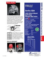
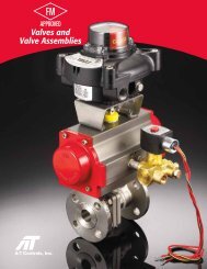
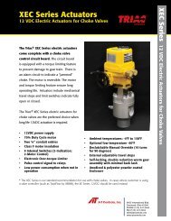
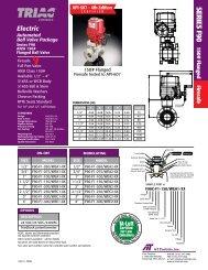
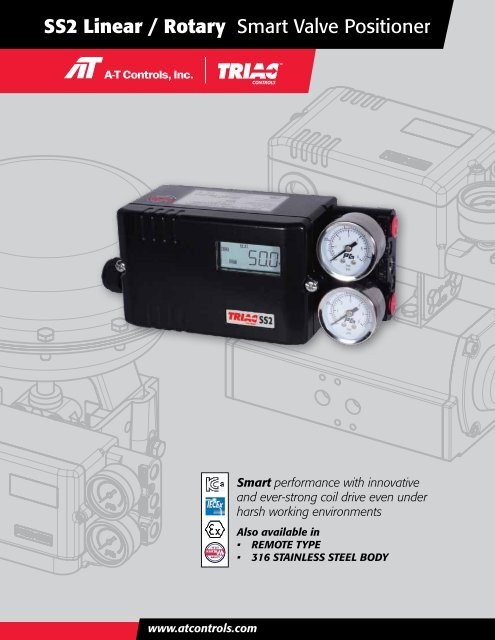
<strong>SS2</strong> <strong>Linear</strong> / <strong>Rotary</strong> <strong>Smart</strong> <strong>Valve</strong> <strong>Positioner</strong>CONTROLSA Division of <strong>AT</strong> <strong>Controls</strong><strong>Smart</strong> performance with innovativeand ever-strong coil drive even underharsh working environmentsAlso available in• REMOTE TYPE• 316 STAINLESS STEEL BODYwww.atcontrols.com
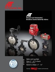
<strong>SS2</strong> <strong>Linear</strong> / <strong>Rotary</strong> <strong>Smart</strong> <strong>Valve</strong> <strong>Positioner</strong><strong>Smart</strong> performance with innovative and ever-strongcoil drive even under harsh working environmentsFE<strong>AT</strong>URES• Easy and quick auto-calibration• Detecting RA (reverse acting) or DA (direct acting) automatically regardlessof wrong air connections• Available to use for single or double acting without any special adjustments• Compact design allowing to be installed on small actuators• Provide error messages against performance failures• Possible to test the actuator with any fixed signal under a test mode• Programmable characteristic curve with 17 points• Wide operating temperature range -30 ~ +80° C• Improved control of high-friction globe and ball valves by eliminatingovershoot and hunting• Low air consumption• Mounting bracket to meet IEC 60534-6-1 for linear valves• Support a NAMUR mounting pattern VDI/VDE 3845 (IEC 60534-6-2) andproviding a multi-size mounting bracket for rotary valves<strong>SS2</strong>L (<strong>Linear</strong> Type)OPTIONS• Output position transmitter (4 - 20 mA)• 2 x alarm limit or micro switch (SPDT)• Explosion proof type (IECEx / <strong>AT</strong>EX / KC Ex ia IIC T5)• HART communication• Profibus communication (in progress)• Fieldbus Foundation communication (in progress)<strong>SS2</strong>R (<strong>Rotary</strong> Type)2
CONTROLSA Division of <strong>AT</strong> <strong>Controls</strong>SPECIFIC<strong>AT</strong>IONSInput SignalMin. / Max. CurrentVoltage Drop (Resistance)Stroke / AngleAir Supply PressureOutput Pressure RangeAir CapacityAir ConsumptionCharacteristicPerformance CharacteristicLCD IndicationAdjustable SpeedScan TimeShut-off Value<strong>Valve</strong> ActionOperating TemperaturePneumatic ConnectionsElectrical ConnectionsProtection ClassBody MaterialWeight* Up to 200mm on request ** -40°C on request4 - 20 mA @ 24 VDC3.6 mA / 50 mAWithout Hart : 8.7 VDC (435Ω @ 20 mA)With Hart : 9.4 VDC (470Ω @ 20 mA)<strong>Linear</strong> type : 5 - 130 mm<strong>Rotary</strong> type : 25 - 120°1.4 - 7.0 bar ( 20 - 100 psi ), filtered, compressed dry and non-oiled to meet Class 3 of ISO 8573-10 - 100% of supply air pressure80 l/min = 4.8 Nm 3 /h = 2.8 scfm (Sup = 20 PSIG)233 l/min = 14 Nm 3 /h = 8.2 scfm (Sup = 90 PSIG)2 l/min = 0.12 Nm 3 /h = 0.07 scfm (Sup = 20 ~ 90 PSIG)<strong>Linear</strong>ity < ±0.3% F.S Sensitivity < 0.2% F.SHysteresis < 0.2% F.SRepeatability < 0.2% F.S<strong>Linear</strong>, EQ %, Quick open, User set (17 points)4-digit LCD indicator1 - 1000 (lowest 1, highest 1000)2msRange 0 - 10% of position signaldirect action (DA) / reverse action (RA)- 30 ~ +80°C (- 22 ~ +176°F ) **NPT 1/4NPT 1/2IP66, intrinsically safe (IECEx / <strong>AT</strong>EX / KC Exia IIC T5)Aluminum die-cast / powder-painted3.5 LBS.*PRINCIPALS OF OPER<strong>AT</strong>IONDigital Control CircuitI/P Converting Process~~ELECTRONICCOILOUT 1OUT 2XVALVE POSITIONSENSOR~MICRO SWITCHESSWITCH 1, 2If 4-20 mA input signal is supplied, the micro processor compares input signal with position feedback and sendscontrol signal to the I/P converting module. Pneumatic signal from the I/P converting module operates the valveand the valve stays at the desired position.www.atcontrols.com3
<strong>SS2</strong> <strong>Linear</strong> / <strong>Rotary</strong> <strong>Smart</strong> <strong>Valve</strong> <strong>Positioner</strong>MOUNTING TO <strong>SS2</strong>L (<strong>Linear</strong> Type)Feedback pinguide leverOUT1OUT2SUP< Front View >< Side View > < Feedback Lever Connection >“A” Type“B” Type3043Mounting on yokewith plane surfaceFeedback pinguide lever‘U’ bolts for pillarmounted actuatorsCenter bolt for yokemounted actuators43“C” Type6573.5 75148.5130Feedback LeverMounting to linear actuators to IEC 60534 6-1MOUNTING TO <strong>SS2</strong>R (<strong>Rotary</strong> Type)<strong>SS2</strong>RSMART POSITIONERActuatorActuatorHLROTARY ACTU<strong>AT</strong>ORNAMUR TypeMounting( VDI/VDE 3845,IEC 60534-6-2 )Fork Lever TypeMountingSize Variation of Multi-Size Bracket1) 80 x 30 x 20 (H) , 4) 130 x 30 x 20 (H)2) 80 x 30 x 30 (H) , 5) 130 x 30 x 30 (H)3) 80 x 30 x 50 (H) , 6) 130 x 30 x 50 (H)H : <strong>Rotary</strong> Actuator Shaft HeightL : Length ( 80 or 130mm )4
CONTROLSA Division of <strong>AT</strong> <strong>Controls</strong>AIR CONNECTIONS <strong>SS2</strong>L (<strong>Linear</strong> Type)DA 1RA 1OUT 1OUT 1DA 2DA 3INPUT -+ INPUT -+INPUT + -OUT2SUPOUT2SUPOUT 1SUPRA 2RA 3INPUT -+ INPUT -+INPUT + -OUT 1SUPOUT2SUPOUT2SUPAIR CONNECTIONS <strong>SS2</strong>R (<strong>Rotary</strong> Type)Spring Return Double Acting Double ActingINPUT + - INPUT +SUP - INPUT +SUP -SUPAs the input signal increases,Actuator shaft rotates counter-clockwiseAs the input signal increases,Actuator shaft rotates counter-clockwiseAs the input signal increases,Actuator shaft rotates clockwisewww.atcontrols.com5
<strong>SS2</strong> <strong>Linear</strong> / <strong>Rotary</strong> <strong>Smart</strong> <strong>Valve</strong> <strong>Positioner</strong>FRONT COVER REMOVED1 : Air supply2 : OUT 13 : OUT 24 : Display LCD5 : Up key6 : Mode key7 : Enter key8 : Down key9 : Input signal (+, -)10 : Frame ground11 : Output signal (+, -)12 : Alarm limit 113 : Alarm limit 214 : Electrical connections15 : Ground16 : Feedback leverELECTRICAL CONNECTIONSAlarm limit 1, 2Input signalOutput signalMicro switches 1, 2CHARACTERISTICSButtonActionAuto -CalibrationPush 5 seconds for auto-calibrationUser SetSpanorPush 5 secondsto change a measured span(Try this option only when a valvedoesn’t reach a desired position)AmbientTemp.Confirm an ambient temperaturesurrounding this smart valve positioner6
CONTROLSA Division of <strong>AT</strong> <strong>Controls</strong>PARAMETERS DIAGRAMShows the operating situation of the positionerChanges the parametersDecides LCD display mode in mA, % or a reverse wayConverts to the manual modeShows the selected parameters and a total valve runtimePerforms auto-calibration and resets all programmed valuesMain parametersTests in process of 2-step, 4-step, or 10...100%Locks the set valuesParameterDescriptionFunctionDefaultINPUInput signal4 ~ 20mA or 20 ~ 4mA4 ~ 20mAR/DARA/DAReverse acting or direct actingAuto-setL/EQCharacteristic<strong>Linear</strong>, E.Q.%(1:25 or 1:50), Quick open or User set(17points)<strong>Linear</strong>SPANSpan adjustment0 ~ 100%100%ZEROZero adjustment0 ~ 99%0%PIDP-GN / I-GN / D-GNProportional / Integral / Differential gain valueAuto-setSPEDResponse speed1 ~ 10001000SWSTSlow startSmooth operation (ON or OFF)Auto-setCNLTControl limit50 ~ 1250Auto-setGCNLGap control limit50 ~ 1250Auto-setDEADDead band0 ~ 9.99%0.5%FDGND-gain setting for hard modeD-Gain setting for hard modeAuto-setC/MDNORM / HARD / SMALStandard actuator, strong valve packing friction, small actuatorNORMSHUTShut-off0 ~ 9.9%0.3%FOPNFull-open0 ~ 9.9%0.3%OUTOutput signal4 ~ 20mA or 20 ~ 4mA4 ~ 20mASPLTSplit range4 ~ 12mA or 12 ~ 20mA4 ~ 20mADIGNDisplay placeMovement to one or two decimal places1ALAMAlarm limit low, highAL1L / AL1H / AL2L / AL2H0 ~ 10%, 90 ~ 105%ICALIN4M / IN20Internal match with 4~20mA input signals from a calibratorFactory settingFCALFB4M / FB20Internal match with 4~20mA output signals to a calibratorFactory settingPOLLPolling addressHART Communication polling address (0 ~ 15)0www.atcontrols.com7
<strong>SS2</strong> <strong>Linear</strong> / <strong>Rotary</strong> <strong>Smart</strong> <strong>Valve</strong> <strong>Positioner</strong>WIRING ALARM LIMITSMICRO SWITCHES (SPDT)positioner24 VDC24 VDCNote that 24 VDC should be supplied for power.11 12 13 14 15 16NO NC COM NO NC COMSwitch 1 Switch 2MEASURING OUTPUT SIGNAL1000Micro SwitchesTypeRatingSPDT10.1A @ 250 VAC12 - 30 VDCCal.750650500250Ambient TemperaturePosition TransmitterOutput SignalPower SupplyOutput Current Limit-30 ~ +85° C4 - 20 mA, 2-wire12 - 30 VDC30 mA DCZERO and SPAN of positionfeedback are automatically setafter auto-calibration process.010 20 30 VDC12 VDC 24 VDC (NOR.)< Transmitter Load Limitation ><strong>Linear</strong>ityOperating Temperature±0.5% F.S-30 ~ +80° CHOW TO ORDER<strong>SS2</strong> ActuatorOperationProtectionClassFeedbackLeverPressureGaugesBy-passPositionFeedbackCommunicationConnectionThreadsMountingBracketFeedback PinGuide LeverSetActuator Operation :Protection Class :Feedback Lever :- <strong>Linear</strong> type :- <strong>Rotary</strong> type :Gauge Block :By-pass :LRIK :W :ABCDFN012NY::::::::::::::<strong>Linear</strong> type<strong>Rotary</strong> typeIntrinsically safe(IECEx Ex ia IIC T5 /<strong>AT</strong>EX Eex ia IIC T5)Intrinsically safe(KC Ex ia IIC T5)Weatherproof to IP66Stroke (5~30mm)Stroke (5~65mm)Stroke (5~130mm)Stroke (80~200mm)Fork leverNAMUR shaft (direct mounting)Not mounted6 bar (90 psi)10 bar (150 psi)None (standard)Yes (auto/manual screw)Position Feedback :Communication :Connection Threads :(pneumatic - electrical)Mounting Bracket :Feedback Pin GuideLever Set :(only for linear type <strong>SS2</strong>L)NONHPF345NLR01::L :S :M :Q :::::::::::::NonePosition transmitter(4~20mA output signal)2 x alarm limit2 x micro switch (SPDT)O + LO + SNoneHARTProfibus (in progress)Fieldbus (in progress)PT(Rc) 1/4 - PF(G) 1/2NPT 1/4 - NPT 1/2PT(Rc) 1/4 - M20 x 1.5NoneIEC 60534-6-1 (for <strong>SS2</strong>L)IEC 60534-6-2 (for <strong>SS2</strong>R)VDI/VDE 3845Not includedIncluded8
CONTROLSA Division of <strong>AT</strong> <strong>Controls</strong>DIMENSIONS <strong>SS2</strong>L (<strong>Linear</strong> Type)3-PT1/413912OUT 1OUT 2GROUND87.5151528 28157.5Electrical connections188.5SUP35.573.588.125.7< Without Gauge Block >P.C.D 504-M6359.56573.588.123.735.55111.5Without Gauge BlockDIMENSIONS <strong>SS2</strong>R (<strong>Rotary</strong> Type)62.23523 18.84-M8139OUT 13-PT1/412OUT 2GROUND87.523.728 28151535.5Electrical connections188.5SUP35.573.51122714< Fork Lever Type >25.7P.C.D 504-M6359.55165DIMENSIONS <strong>SS2</strong> with 2 x SPDT Micro S/W62.23523 18.84-M811.5With Gauge Block35.573.587.525.7www.atcontrols.com9
<strong>SS2</strong> <strong>Linear</strong> / <strong>Rotary</strong> <strong>Smart</strong> <strong>Valve</strong> <strong>Positioner</strong>DIMENSIONS R<strong>SS2</strong> (Remote Type)< <strong>Linear</strong> Type Remote Position Unit >6594.54535.44945Connector79.632.517.717.72-M63-M8Ø9159.6Cable length: 3, 5, 10, 15m32.5161268.416CABLE CONNECTOR< <strong>Rotary</strong> Type Remote Position Unit >654535.44994.545<strong>Linear</strong> typeRemote position unit<strong>Rotary</strong> typeRemote position unit79.632.517.717.72-M63-M8Ø9159.632.5100°6CABLE CONNECTORHOW TO ORDER R<strong>SS2</strong> (Remote Type)NOTE: All sepecifications and characteristics are the same with <strong>SS2</strong>R<strong>SS2</strong>ActuatorOperationProtectionClassFeedbackLeverPressureGaugesBy-passPositionFeedbackCommunicationConnectionThreadsCableLengthActuator Operation :LR::<strong>Linear</strong> type<strong>Rotary</strong> typeBy-pass :NY::NoneYes (auto/manual screw)Protection Class :Feedback Lever :- <strong>Linear</strong> type :- <strong>Rotary</strong> type :Gauge Block :IK :W :ABCF012::::::::Intrinsically safe(IECEx Ex ia IIC T5,<strong>AT</strong>EX Eex ia IIC T5)Intrinsically safe(KC Ex ia IIC T5)Weatherproof to IP66Stroke (5~40mm)Stroke (5~80mm)Stroke (5~150mm)Fork leverNot mounted6 bar (90 psi)10 bar (150 psi)Position Feedback :Communication :Connection Threads :(pneumatic - electrical)Cable Length :NOL :M :NHPF345:::::::::NonePosition transmitter(4~20mA output signal)2 x alarm limitO + LNoneHARTProfibus (in progress)Fieldbus (in progress)PT(Rc) 1/4 - PF(G) 1/2NPT 1/4 - NPT 1/2PT(Rc) 1/4 - M20 x 1.53, 5, 10, 15mOther : On request10
CONTROLSA Division of <strong>AT</strong> <strong>Controls</strong><strong>SS2</strong>SL & <strong>SS2</strong>SR (Stainless Steel 316 Body)HOW TO ORDER <strong>SS2</strong>SL & <strong>SS2</strong>SRInput SignalMin. / Max. CurrentVoltage Drop (Resistance)Stroke / AngleAir Supply PressureOutput Pressure RangeAir CapacityAir ConsumptionCharacteristicPerformance CharacteristicLCD IndicationAdjustable SpeedScan TimeShut-off Value<strong>Valve</strong> ActionOperating TemperaturePneumatic ConnectionsElectrical ConnectionsProtection ClassBody MaterialWeight4 - 20 mA @ 24 VDC3.6 mA / 50 mAWithout Hart : 8.7 VDC (435Ω @ 20 mA)With Hart : 9.4 VDC (470Ω @ 20 mA)<strong>Linear</strong> type : 5 - 130 mm<strong>Rotary</strong> type : 25 - 120°1.4 - 7.0 bar (20 - 100 psi)0 - 100% of supply air pressure80 l/min = 4.8 Nm 3 /h = 2.8 scfm (Sup = 20 PSIG)233 l/min = 14 Nm 3 /h = 8.2 scfm (Sup = 90 PSIG)2 l/min = 0.12 Nm 3 /h = 0.07 scfm (Sup = 20 ~ 90 PSIG)<strong>Linear</strong>ity < ±0.3% F.SHysteresis < 0.2% F.S* Up to 200mm on request ** -40° C on request<strong>Linear</strong>, EQ %, Quick open, User set (17 points)4-digit LCD indicator1 - 1000 (lowest 1, highest 1000)2msRange 0 - 10% of position signalDirect action(DA) / Reverse action(RA)- 30 ~ +80° C (- 22 ~ +176° F) **NPT 1/4 (other on request)NPT 1/2 (other on request)IP66, intrinsically safe (IECEx / <strong>AT</strong>EX / KC Exia IIC T5)Stainless steel 3168.5 LBS. (without bracket)*Sensitivity < 0.2% F.SRepeatability < 0.2% F.S<strong>SS2</strong>S ActuatorOperationProtectionClassFeedbackLeverPressureGaugesBy-passPositionFeedbackCommunicationConnectionThreadsMountingBracketFeedback PinGuide LeverSetActuator Operation :Protection Class :Feedback Lever :- <strong>Linear</strong> type :- <strong>Rotary</strong> type :Gauge Block :By-pass :LRIK :W :ABCDFN012NY::::::::::::::<strong>Linear</strong> type<strong>Rotary</strong> typeIntrinsically safe(IECEx Ex ia IIC T5 /<strong>AT</strong>EX Eex ia IIC T5)Intrinsically safe(KC Ex ia IIC T5)Weatherproof to IP66Stroke (5~30mm)Stroke (5~65mm)Stroke (5~130mm)Stroke (80~200mm)Fork leverNAMUR shaft (direct mounting)Not mounted6 bar (90 psi)10 bar (150 psi)NoneYes (auto/manual screw)Position Feedback :Communication :Connection Threads :(pneumatic - electrical)Mounting Bracket :Feedback Pin GuideLever Set :(only for linear type <strong>SS2</strong>SL)NONHPF4 : NPT 1/4 - NPT 1/2NLR01::L :S :M :Q ::::::::::NonePosition transmitter(4~20mA output signal)2 x alarm limit2 x micro switch (SPDT)O + LO + SNoneHARTProfibus (in progress)Fieldbus (in progress)NoneIEC 60534-6-1 (for <strong>SS2</strong>SL)IEC 60534-6-2 (for <strong>SS2</strong>SR)VDI/VDE 3845Not includedIncludedwww.atcontrols.com11
<strong>SS2</strong> <strong>Linear</strong> / <strong>Rotary</strong> <strong>Smart</strong> <strong>Valve</strong> <strong>Positioner</strong>9955 International Blvd.Cincinnati, Ohio 45246P: 513 - 247 - 5465F: 513 - 247 - 5462sales@atcontrols.comwww.atcontrols.comCONTROLSA Division of <strong>AT</strong> <strong>Controls</strong>20120822<strong>SS2</strong>