AUMA Matic Integral Controls - RM Headlee
AUMA Matic Integral Controls - RM Headlee
AUMA Matic Integral Controls - RM Headlee
- No tags were found...

You also want an ePaper? Increase the reach of your titles
YUMPU automatically turns print PDFs into web optimized ePapers that Google loves.
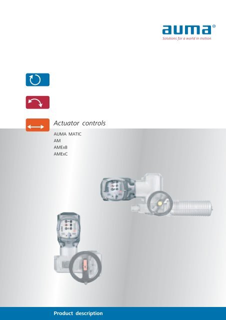
ApplicationsElectric actuators are used for the automation of industrialvalves. A suitable actuator is available for nearly allvalve applications.<strong>Integral</strong> controls are the ideal interface between theactuator and the DCS. The actuators are perfectly controlledand the integration of the actuator into the DCS ismade much simpler.Power: Conventional power plants(coal, gas, oil): Hydroelectric power plants: Geothermal power plants: Solar thermal power plants: Biogas power plantsOil & gas: Exploration, offshore plants: Refineries: Distribution: Gas tanks: Tank farms2 |Water sector: Sewage treatment plants: Water treatment plants: Drinking water distribution: Seawater desalination: Steel construction for water resourcesIndustrial and specialsolutions:: Air conditioning: Food industry: Chemical/pharmaceutical industry: Vessel and submarine shipbuilding: Steel mills: Paper industry: Cement works: Mining
Table of contentsControl concepts 4Modular design/versions 6Design principle 8Summary of applications, functions,and equipment 9Service conditions 10Interfaces 12Operation/setting 14Functions 16Failure functions 18Signals/indication 22Electrical connectionfor non-explosion-proof actuators 24Electrical connectionfor explosion-proof actuators 25Technical data 26Certificates 27The actuator specialist 28Further literature/Index 29<strong>AUMA</strong> worldwide 30Solutions for a world in motion2010-09-20This brochure will provide both the beginner and theexpert with an overview of the functions and applicationsof <strong>AUMA</strong> MATIC actuator controls. It can be used as abasis to determine whether a device is suitable for thechosen application. Knowledge on the basic functions ofelectric actuators is a prerequisite for understanding thecontents.For detailed product selection refer to the separate datasheets and price lists. On request, <strong>AUMA</strong> engineers withinfield service and within our subsidiaries can help you findthe correct device for the application.In the mid-1970s, the first integral actuator controlswere introduced. They replaced the complex actuator controlslocated in control cabinets and simplified installation,commissioning and connection of the devices to the DCS.The continuously growing market for devices with integralcontrols proves the success of this concept. 70 % of theactuators delivered by <strong>AUMA</strong> are equipped with integralcontrols now.The latest detailed information on the <strong>AUMA</strong> MATICactuator controls can be found on the Internet underwww.auma.com. All documents, including dimensionaldrawings, wiring diagrams and final inspection records forsupplied devices are available on the Internet in digitalform.Subject to change without notice.The product features and technical data provided do not express or imply any warranty.| 3
Control conceptsWhy do I need controls?An electric actuator in the classical sense, i.e. without integralcontrols, consists of the following components:■■an electric motor.gearing for the reduction of the motor speed to the requiredoutput speed and for the transmission of the motortorque into the output torque.[2][1]TSCLSAThLSCLSBTSOBLLSORWG■■■a handwheel for manual emergency operation.limit switching for measuring the travel.torque switching for measuring the torque present at thevalve.However, there is no switch for switching the device on oroff. Nor does this basic actuator have any switchgear forreversing control of the motor as required to operate theactuator in both directions or any logic to process the torqueand limit signals.SA multi-turn actuator and SG part-turn actuator without integral controlsAdditional equipment is required, the so-called actuatorcontrols, to be able to control the actuator via the DCS.Tasks of the actuator controls■ Processing the operation commands from the DCS and appropriatecontrol of the actuator motorSignals from a fully equipped <strong>AUMA</strong> actuator[1] Actuator controls[2] Control signals from the DCS or feedback signals to the DCS[TSC] Torque switch signal in direction CLOSE[LSC] Limit switch signal in end position CLOSED[TSO] Torque switch signal in direction OPEN[LSO] Limit switch signal in end position OPEN[LSA] Intermediate position switch signal in direction CLOSE (option)[LSB] Intermediate position switch signal in direction OPEN (option)[BL] Blinker transmitter signal, option for actuators for modulating duty[RWG] Electronic position transmitter, 0/4 – 20 mA (option)[Th] ThermoswitchAs explained before, there are several options to implementactuator controls. Depending on the plant configuration,the most favourable solution should be selected. <strong>AUMA</strong>sales engineers will help you choose the best solution.■■■Providing the signals for the DCSProcessing the signals from the actuator and automaticswitchingProviding local operation with indication of the device statusfor commissioning4 |
Control concepts[a]: DCS[b]: Multicore signal cable[c]: Power supply[d]: Local controls[1] External controlsFor actuators to be connected to externalcontrols, the following must be considered:■ All actuator signals e.g. limit, torque andthermoswitch signals must be passed on tothe external controls in the control cabinet.A separate signal channel is required foreach signal.■ The control of the actuators via a reversingcontactor combination has to be implementedand installed in the control cabinet.■ The local controls have to be implementedand mounted.■ Depending on the valve type, the signalshave to be processed differently(torque/limit seating).External controls require extensive planningand installation. If mistakes are made during installation,commissioning may be hazardous.The documentation of the controls is extensive.[2] <strong>Integral</strong> controlsActuators with integral controls are immediatelyready for use. As soon as the power supplyhas been established, the actuator can beoperated via the operating elements on the localcontrols. The actuator can be set up completelyon site; only operation commands andfeedback signals are exchanged between theDCS and the actuator. The sensor signals of theactuators are processed internally. <strong>Integral</strong> protectivefunctions prevent damage duringcommissioning.Further advantages■ No extensive wiring in the control cabinet isrequired■ Reliable and correct processing of the actuatorsignals.■ Actuator and controls are optimally adaptedto each other■ Standard wiring diagrams are available■ Warranty for both actuators and controls[e]: Fieldbus interface[f]: Fieldbus cable (2-wire cable or fibre opticcable)[3] FieldbusBy using a single data transmission mediumfor all signals from many devices, the structureof fieldbus systems can be kept very clear andsimple. Where the control cabinet of commonlyused systems is filled with input and outputsub-assemblies, the fieldbus only requires a singleinterface.Compared to common installations, the fieldbussystems have expanded functions. This includessetting of the field devices via the DCS.The integral <strong>AUMA</strong> actuator controls are availablewith interfaces to all common fieldbussystems.| 5
Modular design/versionsModular design – with suitable controlsEach application has its special requirements. For this reason,<strong>AUMA</strong> only builds actuators on demand – tailor-made tocustomer requirements. Due to the modular design of the<strong>AUMA</strong> product range, different features can be combined.For each actuator type, there are a large number of equipmentvariants.One of the central features of <strong>AUMA</strong>’s modular design isthe ability to supply or retrofit integral controls onto the basicactuator.As well as the <strong>AUMA</strong> MATIC’s functionality, the <strong>AUMA</strong>TICoffers some other advantages, e.g.■■■■Programmable signal relaysNon-intrusive setting in combination with theMWG control unit in the actuator (option)Adaptive positioner (option)Fieldbus interfaces for Profibus DP, Modbus RTU,DeviceNet, Foundation Fieldbus (option)<strong>AUMA</strong> MATIC or <strong>AUMA</strong>TIC■■■Monitoring and diagnosticsLogging of operating dataCable-based or wireless programming interface for connectinga programming deviceFor detailed information on the <strong>AUMA</strong>TIC, refer to thebrochure, Actuator controls <strong>AUMA</strong>TIC .<strong>AUMA</strong> SA or SG actuators can be equipped with <strong>AUMA</strong> MATIC or<strong>AUMA</strong>TIC controls.In its basic version, the <strong>AUMA</strong> MATIC is the ideal andmost economic controller for simple OPEN - CLOSE applicationswith conventional signal transmission.The <strong>AUMA</strong> MATIC provides end position indication, theselector switch position and a collective fault signal, all asfeedback signals.The behaviour of the <strong>AUMA</strong> MATIC can be adapted to theapplication via programming switches, e.g. setting the type ofseating.As an option, the device can be used for closed-loop control,and is, furthermore, available with a Profibus DP or aModbus RTU interface.This brochure provides a detailed description of the <strong>AUMA</strong>MATIC.6 |
[1][2][1a][1c][1b][3][1] Modular design 1Universal control concept<strong>AUMA</strong> actuator controls can be combinedwith the different actuator types. Even with differentactuator types within a plant, a universalconcept with regards to the connection to theDCS and device operation/setting can be maintained.The controls are available for the followingactuator ranges:■ Multi-turn actuators for open-close dutySA 07.1 – SA 16.1SAExC 07.1 – SAExC 16.1■ Multi-turn actuators for modulating dutySAR 07.1 – SAR 16.1SARExC 07.1 – SARExC 16.1■ Part-turn actuators for open-close dutySG 05.1 – SG 12.1SGExC 05.1 – SGExC 12.1SG 03.3 – SG 04.3■ Part-turn actuators for modulating dutySGR 05.1 – SGR 12.1SGR 03.3 – SGR 04.3[1a] Multi-turn actuator of size SA 10.1(max. 120 Nm)[1b] Multi-turn actuator of size SA 16.1(max. 1,000 Nm)[1c] Part-turn actuator of size SG 05.1(max. 150 Nm)[2] Modular design 2Plug/socket connectionsThe controls can be mounted on the actuatorat 90° intervals, the electrical connectionand the local controls can be positioned in thesame way. The connections are plug andsocket which enables the actuator and controlsto be adapted to the installation situation inthe plant in no time at all. Further advantagesof the plug/socket connection are high ease ofservice and once electrical connections havebeen established, they do not have to beseparated again.[3] Modular design 3Wall bracketThe controls can be mounted separatelyfrom the actuator on a wall bracket. This is recommendedif:■ the actuator is installed in an inaccessibleplace, e.g. in a shaft.■ high ambient temperatures at the valve mayinfluence the control electronics.■ heavy valve vibration could influence thecontrol electronics.| 7
Design principle[7][6][1][2][3][5][4][1] Electrical connectionDifferent plug/socket connectors are availablefor the electrical connection. The differentversions for standard or explosion-proof devicesare described on pages 24 and 25.For maintenance work, the actuator can be disconnectedquickly from the power supply andcontrol cables and can easily be reconnected.[4] Plug/socket connector to the actuatorThe electrical connection between the integralcontrols and the actuator is made by usinga plug/socket connector. Four screws are usedto attach the controls housing to the actuator.For maintenance purposes the controls can beseparated and reconnected to the actuator inno time at all.[7] InterfaceThe interface forms the link to the processcontrol system. Here, the commands from theprocess control system are received and signalsissued. Depending on the DCS, parallel controlwith or without positioner or fieldbus, the<strong>AUMA</strong> MATIC is equipped with the correspondinginputs and outputs.[2] Power supply unitThe power supply for the internal electronics,the heating system and the position transmitters(option) within the actuator.[3] SwitchgearIn the standard version, reversing contactorswith a maximum switching power of 7.5 kWare used for motor power switching. For applicationsrequiring a high number of starts, werecommend the use of thyristor units. Apartfrom a longer lifetime, they have shorter reactiontimes. Thyristor units are available up to amaximum power of 5.5 kW.[5] Local controlsThe local controls contain all operating elementsrequired to operate and set the actuatorlocally. A selector switch is used to select Localoperation or Remote operation or to disable alloperation commands when set to (0).In addition, three indication lights show differentactuator states (refer also to the Signals/indicationsection as from page 22).[6] LogicThe logic processes all external and internalsignals. The programming switches can beused, e.g., to determine the type of seating inthe end positions, to determine whether theoperation commands are processed inpush-to-run operation or in the self-retainingmode or to program the collective fault signal.In case of faults, e.g. tripping of the motor protection,when reaching an end position or incase of a stop command, the logic switches offthe actuator directly and without significantdelay time.8 |
Summary of applications, functions, and equipmentStandard ●Option ■<strong>AUMA</strong> MATICAMAMExB/AMExCService conditionsParallel Fieldbus Parallel Fieldbus PageEnclosure protection IP 67 ● ● ● ● 10Enclosure protection IP 68 ■ ■ ■ ■ 10Corrosion protection KN ● ● ● ● 10Corrosion protection KS, KX ■ ■ ■ ■ 10Low temperature versions ■ ■ ■ ■ 11Explosion protection – – ● ● 11InterfaceParallel interface ● – ● – 12Fieldbus interface – ● – ● 13Operation/settingLocal operation ● ● ● ● 15Setting ● ● ● ● 15FunctionsLimit seating ● ● ● ● 16Torque seating ● ● ● ● 16OPEN - STOP - CLOSE control ● ● ● ● 17Setpoint control (positioning) ■ ■ ■ ■ 17Failure functionsAutomatic phase correction ● ● ● ● 18Overload protection of the valve ● ● ● ● 19Protection of the motor against overheating ● ● ● ● 17Phase failure monitoring ● ● ● ● 20Failure behaviour on loss of signal ■ ■ ■ ■ 20Protection against unauthorised operation/setting ● ● ● ● 21Feedback signals/local indicationFeedback signals for parallel interface ● ● ● ● 22Feedback signals for fieldbus interface ● ● ● ● 23Local indication ● ● ● ● 23SwitchgearReversing contactors ● ● ● ● 8Thyristors ■ ■ – – 8Electrical connection for non-explosion-proof devicesElectrical connection with plug/socket ● ● – – 24Expanded connection compartments ■ ■ – – 24Double sealed ■ ■ – – 24Protection cover ■ ■ – – 24Parking frame ■ ■ – – 24Electrical connection for explosion-proof devicesPlug/socket connector for explosion-proof actuators – – ● ● 25Plug-in terminal connection for explosion-proof actuators – – ■ ■ 25Double sealed – – ● ● 25Protection cover – – ■ ■ 25Parking frame – – ■ ■ 25| 9
Service conditions<strong>AUMA</strong> devices are used worldwide; in all climate zones, inindustrial plants of all kinds under special local ambient conditions.<strong>AUMA</strong> devices have to operate reliably and for a longtime under any conditions without requiring major maintenancework. For this very reason, <strong>AUMA</strong> has focussed onmaking <strong>AUMA</strong> devices resistant to the most unfavourableconditions and have adapted their protective measures to thestate-of-the-art technology.Enclosure protectionIP 67<strong>AUMA</strong> devices conform to enclosure protection IP 67according to EN 60 529. IP 67 means protection againstimmersion up to max. 1 m head of water for max. 30 minutes.IP 68On request, <strong>AUMA</strong> devices are available with improvedenclosure protection IP 68 according to EN 60 529. IP 68means protection against submersion up to 6 m head ofwater for max. 72 hours. During submersion up to 10 operationsare permissible.In order to guarantee the enclosure protection IP 68, suitablecable glands must be used. They are not part of thestandard supply, but can be provided by <strong>AUMA</strong> on request.<strong>AUMA</strong> actuators at work – in Siberia and in the SaharaAmbient temperatures<strong>AUMA</strong> MATICAMExplosion-proof <strong>AUMA</strong> MATICAMExBExplosion-proof <strong>AUMA</strong> MATICAMExC–25 °C … +70 °CVersionsTemperature rangeStandardExtreme low temperature 1 –60 °C … +70 °CLow temperature–40 °C … +70 °CStandard –20 °C … +40 °C/60 °C 2–20 °C … +40 °C/60 °C 2 /70 °C 3StandardExtreme low temperature 1 –50 °C … +40 °C/60 °C 2Low temperature–40 °C … +40 °C/60 °C 2Some of the permissible ambient temperature ranges of <strong>AUMA</strong> actuators differ from those of the <strong>AUMA</strong> MATIC. This hasto be observed during sizing.1Device includes heating system for connection to external power supply 230 V AC or 115 V AC.2For the temperature range up to +60 °C, special sizing of the actuator is required for temperature class T4.3+70 °C in combination with explosion group IIB and temperature class T310 |
Corrosion protection/colourStandard (KN)The standard <strong>AUMA</strong> corrosion protection KN is a highquality coating. This is suitable for outdoor installation andfor slightly aggressive atmospheres with a low level ofpollution.KS<strong>AUMA</strong> recommends this corrosion protection class forinstallation in occasionally or permanently aggressive atmosphereswith a moderate pollutant concentration.KX<strong>AUMA</strong> recommends this corrosion protection class forinstallation in aggressive atmosphere with high humidity anda high pollutant concentration.ColourThe standard colour of the finish coating is silver-grey (similarto RAL 7037). Other colours are available on request.Explosion protectionFor the installation of actuators in potentially hazardous orexplosive areas, special protective measures are required.These are stipulated in the European Standards EN 50 014,50 018, and 50 019. The PTB (Physikalisch TechnischeBundesanstalt, the German national test authority) and theBVS (German Mining Test Facility) as European test authoritieshave certified the conformity of the equipment with thementioned standards.Explosion protection classesTypesMulti-turn actuatorsSAExC 07.1 – SAExC 16.1SARExC 07.1 – SARExC 16.1with AMExB or AMExCPart-turn actuatorsSGExC 05.1 – SGExC 12.1with AMExCClassification■ II2G EEx de IIC T3 or T4■ II2G c IIC T4■ II2D Ex tD A21 IP6X T130°C■ II2G EEx de IIC T4■ II2G c IIC T4■ II2D Ex tD A21 IP6X T130°CCertificates of Conformity from national test authorities inother countries, such as USA, Canada, CIS, Brazil, Japan, etc.,are also available.| 11
InterfacesWhile the mechanical interface between actuator andvalve is defined by a few standards worldwide, there is alarge variety of connections from the actuator to the DCS.Selecting the proper connection is not just reduced to decidingbetween conventional parallel control or fieldbus, it isalso a question of redundancy concepts, transmission media,etc.Whatever the requirements, <strong>AUMA</strong> keeps track of the latestdevelopments: not only with regards to the devices butalso regarding the know-how of our sales engineers or withinour quotations department. Here you can find your competentpartners who will support you in finding the solution torather complex questions on the connection to the DCS.Parallel interfaceFor systems with parallel signal transmission, discrete signalssuch as operation commands are transmitted as 24 V DCsignals (alternatively 115 V AC). Continuous signals such asnominal or actual position values are exchanged as4 – 20 mA signals.Each signal requires a separate signal channel and a separateinput or output at the controls.[1]Parallel wiring or fieldbus with 2-wire technology is no longer the onlyquestion. Fieldbus enables much more comprehensive data exchange andtherefore a more intensive integration of the actuators into the process.Even in the basic version, the <strong>AUMA</strong> MATIC with parallel interface exchangesup to 10 discrete signals with a PLC [1]:■ Three binary inputs for the OPEN, STOP, and CLOSE commands■ Five binary outputs, one reserved for collective fault signal, the remainingfour with signals for end position CLOSED reached, end positionOPEN reached, <strong>AUMA</strong> MATIC in local control, and <strong>AUMA</strong> MATIC in remotecontrol.■ Frequently, an optional analogue output for the transmission of thevalve position if a positioner is included in the actuator.Depending on the functions of the controls, the <strong>AUMA</strong>MATIC might have different configurations. For example, theoptional positioner requires an analogue input for the positionsetpoint.12 |
Fieldbus interfaceIn fieldbus systems, all signals for all devices connected tothe bus are transmitted via a common signal channel. In general,this is a 2-wire cable. The number of cables connectedto the <strong>AUMA</strong> MATIC does not depend on the number offunctions available for the device.Further literatureFor detailed information refer to the brochure: Electricactuators with fieldbus interfaces.<strong>AUMA</strong> MATIC actuator controls are available with the followingfieldbus interfaces:■■Profibus DPModbus RTUFunctionalityCompared to the <strong>AUMA</strong> MATIC with conventional interface,the <strong>AUMA</strong> MATIC with fieldbus interface has expandedfunctions. Thus, the <strong>AUMA</strong> MATIC field bus version can becontrolled via discrete OPEN - CLOSE commands or a continuoussetpoint. Selection between the two modes is made byan additional mode signal.Expanded fieldbus functions with the <strong>AUMA</strong>TIC Bus.Since 2003, <strong>AUMA</strong> has used the <strong>AUMA</strong>TIC AC as a developmentbase for fieldbus technology. Further developmentsof existing fieldbus interfaces and implementation of newinterfaces are solely focussed on the <strong>AUMA</strong>TIC.Furthermore, the <strong>AUMA</strong>TIC is availabe with■■■■DeviceNetFoundation FieldbusComponent redundancyDTM for remote parameter setting■ ....<strong>AUMA</strong>TIC Bus controls are ideal for sophisticated fieldbussolutions.| 13
Operation/settingThe integral local controls allow immediate electric operationafter connection to the power supply.This is not only an advantage during operation but, aboveall, facilitates commissioning. All settings can be made andchecked before actually connecting the actuator to the DCS.Operating and indication elements of the<strong>AUMA</strong> MATIC[1][3][2][1] Push buttonsTo operate or to stop the actuator.[2] Selector switchThe selector switch is used to activate either remote or local control;no electrical operation is possible when set to 0. To prevent unauthorisedoperation, the selector switch can be locked with a padlock.[3] Indication lightsSee page 23A number of double-stem gate valves in a sewage treatment plant. Thecombination between SA multi-turn actuators and GK multi-turn gearboxesare each controlled by one <strong>AUMA</strong> MATIC.14 |
Local operationIf the selector switch is in the local position, the actuatorcan be operated with the OPEN - STOP - CLOSE push buttons.It can be determined for each direction of operation,whether the actuator is run in push-to-run operation orself-retaining. In push-to-run operation, the actuator stopsimmediately when releasing the push button. If self-retainingis set, the actuator runs into one of the end positions or untilthe STOP push button is operated.SettingEnd positions and tripping torques as well as positioners, ifavailable, are set at the actuator.The processing mode of the actuator and DCS signals isthen set at the <strong>AUMA</strong> MATIC. This particularly includes thetype of seating when reaching an end position, either limit ortorque seating.All further settings depend on the features of the respective<strong>AUMA</strong> MATIC controls. Therefore, it is crucial whetherthe <strong>AUMA</strong> MATIC is equipped with a standard interface forOPEN - STOP - CLOSE commands, a positioner for processinga setpoint signal, or a fieldbus interface. For all versions, thesetting elements, the DIP switches and the potentiometer areeasily accessible when removing the housing cover.SG part-turn actuators with <strong>AUMA</strong> MATIC within a combined cyclepower plant in Spain.| 15
FunctionsThe <strong>AUMA</strong> MATIC evaluates all actuator signals to ensuresafe operation of both actuator and valve, irrespective of theDCS programming. This includes correct tripping after reachingan end position, but also failure functions such as theoverload protection.The <strong>AUMA</strong> MATIC offers several control options, asdescribed below.Switching off in the end positionsIf one of the valve end positions is reached the controlsautomatically switch off the actuator.Depending on the valve type, the actuator is switched offaccording to the following procedure:■■Limit seating, i.e. at one of the set switching positionsTorque seating, i.e. with a defined torque<strong>AUMA</strong> actuators include two independent measuring systems,the limit switching and the torque switching.The type of seating is determined by the way the controlsprocess the limit and torque signals.■■If the controls are set to limit seating, the controls switchoff the actuator as soon as a limit signal is received.If the controls are set to torque seating, the controlsswitch off the actuator as soon as the set torque limit hasbeen exceeded. The torque limit is specified by the valvemanufacturer. Due to the additional limit signal the controlsrecognise that the actuator has regularly been trippedin one of the end positions.The type of seating can be set independently for eitherend position.Extreme conditions: Heat combined with salty maritime air. SG part-turnactuators with <strong>AUMA</strong> MATIC within an industrial plant in Qatar.16 |
OPEN - STOP - CLOSE controlShut-off valves are generally either fully opened or closed.For remote operation, the OPEN, STOP and CLOSE operationcommands of the <strong>AUMA</strong> MATIC are supplied. The OPEN -STOP - CLOSE control is also called self-retaining. If the actuatorreceives an operation command, the actuator runs untilreceiving a stop command or a switch-off condition occurs,e.g. the end position is reached.Setpoint control/positioning (option)[2][1][4][3]The OPEN - CLOSE operation (without STOP command),the so-called push-to-run operation, is contrary to this. Theactuator stops as soon as an operation command iscancelled. This type of control is required if the actuator iscontrolled by an external positioner.The <strong>AUMA</strong> MATIC can be set to self-retaining orpush-to-run operation independently in each operation direction.The positioner [1] within the <strong>AUMA</strong> MATIC controls positions the valveaccording to the externally supplied setpoint [2]. Depending on the interface,the setpoint may take the form of a 4 – 20 mA signal or be transmittedas a digital signal via the fieldbus. The positioner requires thecurrent valve position [3] for closed-loop control. The valve position canalso be transmitted to the DCS.The internal positioner removes the need for an externalpositioning device. In combination with a modulating actuatormounted on a modulating valve, you obtain an ideallyadapted unit, which can be integrated into the DCS.Extreme weather conditions at the polar sea. SA multi-turn actuators with<strong>AUMA</strong> MATIC in a tank farm near Arkhangelsk in the North of Russia.| 17
Failure functionsDuring all stages of the actuator’s life, from installationand commissioning right through to operation, external conditionsmay disturb normal operation. The conditions may becaused due to mistakes during commissioning but also due toforeign matter within the valve.<strong>AUMA</strong> actuator controls therefore include a variety of failurefunctions which either eliminate the faults or switch offthe actuator before any damage can be incurred.Your great advantage: There is no need for worst caseassessments and the respective programming within yourcontrols to account for these events.And if such an event occurs, the integral diagnostic functionswill indicate the cause of the fault.Automatic phase correctionMost actuators are driven by three-phase asynchronousmotors. The three phases of the power supply have to beconnected in the correct sequence to make sure these robustmotors run in the right direction. Otherwise, the actuatorwould run in direction CLOSE for an OPEN command andvice versa. In this case, the switch-off features would not takeeffect and the valve may be damaged or even be destroyed.The automatic phase correction prevents this. The controlof the motor is automatically adapted to the 3-phase rotatingfield. Even if the phases were crossed over during installationthe actuator will still run in the direction CLOSE for a CLOSEcommand.Multi-turn actuator/worm gearbox combination in a water treatmentplant in Australia.18 |
Overload protection of the valveExcessive torque puts an extreme load on the valve; thismay cause damage and can, in the worst case, destroy thevalve. The torque switching integrated in the actuator istherefore not only used for regular torque seating in one ofthe end positions: the actuator controls also monitor thetorque switching over the whole travel. If the set torque limitis exceeded, the controls immediately trip the actuator andsignal a torque fault.Protection of the motor against overheatingThe windings of the 3-phase AC and 1-phase AC motorscontain thermoswitches or PTC thermistors which trip as soonas the temperature within the motor exceeds 140 °C.Thermoswitches or PTC thermistors offer far better protectionthan thermal overload relays, since the temperature riseis directly measured at the motor winding.T[1]140 °C[3]115 °C90 °C[2][2]tMotor temperature curve against timeWhen reaching the tripping temperature [1], the <strong>AUMA</strong> MATIC automaticallytrips the actuator and prevents the motor from being damaged dueto overheating. When using thermoswitches, the <strong>AUMA</strong> MATIC automaticallyswitches to the ready state once the motor has cooled down to restarttemperature [2]; when using PTC thermistors, the fault has to beacknowledged.[1]Foreign matter [1] may cause excessive torque. If there was no overloadprotection available, the actuator would act with its maximum torqueupon the foreign matter and therefore upon the valve, only restricted bythe maximum stall torque of the motor. This is prevented by the trippingof the torque switching in the actuator [2] and the switching off via thecontrols [3].| 19
Failure functionsPhase failure monitoringActuators are generally driven by 3-phase AC motors. A3-phase AC supply is required to power these actuators.The electronics within the <strong>AUMA</strong> MATIC is supplied usingtwo of the three phases. If one of the two phases fails, theactuator can no longer be operated.If the remaining phase fails, the controls remain fully operable.The two motor windings which are still supplied wouldtry to compensate for the torque loss caused by the failure ofthe third winding and would therefore overheat. As anotherconsequence, the motor protection would be tripped (seepage 17) and the actuator be switched off.To prevent this chain reaction and to quickly identify thecause of the fault, the <strong>AUMA</strong> MATIC monitors this thirdphase. The controls stop the actuator in case of a loss ofphase and send the loss of phase fault signal.Failure behaviour on loss of signalIf the <strong>AUMA</strong> MATIC is equipped with a positioner or witha bus interface, nominal and actual position values or the bussignal must be permanently available to ensure regular <strong>AUMA</strong>MATIC operation.If one of these signals fails, e.g. due to a loss of the masteror if a cable is cut through, the process can no longer bereliably monitored.In these cases, the <strong>AUMA</strong> MATIC triggers a defined failurebehaviour. During commissioning, you have to determine themost favourable valve position in case of a fault.The <strong>AUMA</strong> MATIC can be set to:■■fail as isThe actuator remains in the current position.fail openActuator moves the valve to end position OPEN.■fail closeActuator moves the valve to end position CLOSED.SA/GK multi-turn combinations with <strong>AUMA</strong> MATIC actuator controlsintegrated in a historical weir in East Germany.20 |
Protection against unauthorised operationThe selector switch for selecting the control mode can beprotected against unauthorised operation, e.g. starting theactuator via the local controls, in any of the three positionsby means of a padlock.Lockable protection cover (option)The lockable protection cover offers increased protection,even against damage to the local controls.Central installation of several <strong>AUMA</strong> MATIC controls within a control cabinetusing the wall bracket facility is also feasible.| 21
Signals/indicationSignals are the foundation for controlling a process flow.For this reason, actuators provide a number of signals whichindicate the operational status of the actuator and the valve.Many applications require that the actuator or the valvestatus can be provided locally. Depending on the equipment,the actuator offers various possibilities.The <strong>AUMA</strong> MATIC evaluates the signals from the sensorswithin the actuator. This includes the discrete signals of thelimit and torque switching, if required continuous valve positionand torque signals, as well as the motor protection.The <strong>AUMA</strong> MATIC uses these signals to generate signalsfor transmission to the DCS.Feedback signals for parallel interfaceDiscrete signalsDiscrete signals include end position signals, status signals,fault signals, and all signals which can be transmitted directlyvia a binary output to the control room.The <strong>AUMA</strong> MATIC when equipped with standard interfacehas five output contacts. One of these contacts is reservedfor the collective fault signal. The five contacts are assignedin the factory as follows:■■■End position OPENEnd position CLOSEDSelector switch in REMOTE■■Selector switch in LOCALCollective fault signal (torque fault, thermal fault and/orphase failure)Continuous signalsIf you require remote position indication, the actuator isequipped with a position transmitter. The position transmitterprovides the valve position as a continuous signal. This signalcan be transmitted as 0/4 – 20 mA to the control room viaan analogue output. If the <strong>AUMA</strong> MATIC is equipped with apositioner, this output is always available. This versionrequires switches with a second switching level for end positionand selector switch signal transmission.Explosion-proof SAExC/GS multi-turn/part-turn actuator combinationswith <strong>AUMA</strong> MATIC mounted on a butterfly valve within a tank farm inthe Azores.22 |
Feedback signals for fieldbus interfaceBoth discrete and analogue signals are digitised in order totransfer them via the bus. By configuring the fieldbus telegramsyou can define which of the signals is transferred tothe control room. A lot more signals can be transferred thanfor devices with a parallel interface. For example, the faultscontained within the collective fault signal are transmitted asindividual signals. For the most extensive process representationof <strong>AUMA</strong> MATIC Profibus DP, 37 discrete and three continuoussignals are transmitted.As a rule, the number of signals transferred should bereduced to the absolute minimum required for the process.Otherwise, the data flow slows down the bus communicationand extends the reaction times.Local indicationIndication lightsThe three indication lights on the local controls give thefollowing signals, from top to bottom:■■■End position OPEN reachedCollective fault signalEnd position CLOSED reachedDepending on the version, the middle indication light canbe additionally assigned a blinking signal for running indication.Position indicatorThe <strong>AUMA</strong> MATIC has no elements for valve position indication.However, <strong>AUMA</strong> part-turn actuators, as a standard,and multi-turn actuators, as an option, are equipped with aposition indicator allowing the valve position to be read onsite.SAExC multi-turn actuators with AMExC controls within the kerosene distributionsystem of Chubu airport in Japan.| 23
Electrical connection for non-explosion-proof actuators<strong>AUMA</strong> non-explosion-proof actuators use a “plug-in” typeelectrical connection. This applies to both power supply andsignal cables. The wiring made during installation remainsundisturbed, even if the actuator has to be disconnectedfrom the mains or the DCS, e.g. for maintenance purposes.The actuator can be quickly reconnected, wiring errors areavoided.The electrical connections can be used for actuators withor without controls.The electrical connection is available in different sizes. Thenumber of cable entries may vary. The cable entries usuallyhave metric threads, Pg- or NPT-threads are also available.[1][2] [3] [4][5][6]All electric connections are based on the<strong>AUMA</strong> plug/socket connector with 50screw-type terminals for connecting the signalcables and three screw-type connections forconnecting the supply voltage.[1] Standard Swith three cable entries. The diameter is100 mm.[2] Enlarged terminal compartment SH (option)with up to six cable entries[3] Enlarged terminal compartment SE (option)with three cable entries. The diameter is135 mm. An intermediate frame is required foradapting to the actuator housing.[4] Double sealed intermediate frame(option)When removing the plug cover or due toleaky cable glands, ingress of dust and waterinto the housing is possible. This is preventedby inserting the double sealed intermediateframe between the electrical connection andactuator housing. The enclosure protection, IP67 or IP 68, will not be affected, even if theelectrical connection is removed. The doublesealed intermediate frame can be combinedwith any of the illustrated electricalconnections.[5] Protection coverfor protecting the plug compartment whenplug is removed.[6] Parking framefor safe mounting of a disconnected plug.24 |
Electrical connection for explosion-proof actuators<strong>AUMA</strong> explosion-proof actuators use a “plug-in” type electricalconnection. This applies to both power supply and signalcables. The wiring made during installation remains undisturbed,even if the actuator has to be disconnected from themains or the DCS, e.g. for maintenance purposes. The actuatorcan be quickly reconnected and wiring errors are avoided.The electrical connection is either designed in the protectiontype “Increased safety” or “Flameproofenclosure”.The electrical connections can be used for actuators withor without controls.Explosion-proof connections are always double sealed: Theflameproof enclosure inside the actuator remains intact evenafter removing the plug cover.[s][2a][1][h][2b][4][3][1] Plug/socket connector with screw-typeterminals KPwith 38 screw-type connections for the signalcables. This connection type is the standardconnection for explosion-proof actuators, evenfor those with a fieldbus interface. The connectioncan be supplied with a standard plug cover(s) with three cable entries or with a high (h)plug cover with up to six cable entries.The connection with the high (h) cover is alsoused for devices with integral controls andfieldbus interface.[2] Plug/socket connector with spring cageterminal blocks KESwith up to 50 spring-cage terminal blocksfor connecting signal cables. Used with operatingvoltages exceeding 525 V and/or if a largenumber of terminals are required. The electricalconnection has up to 6 cable entries.The connection is available in protection type“Increased safety” [2a] or “Flameproofenclosure’”[2b].[3] Protection coverfor protecting the plug compartment whenthe plug is removed.[4] Parking framefor safe mounting of a disconnected plug.The parking frame with mounted plug is protectedagainst the ingress of both dust and water.| 25
Technical dataFor detailed information refer to the separate data sheetsVoltage supplyExternal supply of theelectronics (option)Switchgear (standard)Switchgear (options)ControlFeedback signalsPosition feedback signal(option)Voltage outputAM AM Bus AMExB/AMExCAMExB/AMExCBus3-phase AC 50 Hz: 220 V; 230 V; 240 V; 380 V; 400 V; 415 V; 500 V3-phase AC 60 Hz: 440 V; 460 V; 480 V1-phase AC 1 50 Hz: 220 V; 230 V; 240 V1-phase AC 1 60 Hz: 110 V; 115 V; 120 V24 V DC +20 %/–15 %Current input: Basic version approx. 200 mA, with options up to 500 mAReversing contactors 2) (mechanically and electrically interlocked) for motor power up to 1.5 kWReversing contactors 2) (mechanically and electrically interlocked) for motor power up to 7.5 kWThyristor unit (recommended for modulating actuators) – –for motor power up to 1.5 kW, 500 V AC,– –with internal fusesfor motor power up to 3.0 kW, 500 V AC,– –with internal fusesfor motor power up to 5.5 kW, 500 V AC,– –external fuses requiredStandardvia bus Standardvia busControl inputs 24 V DC, OPEN - STOP - CLOSEControl inputs 24 V DC, OPEN – STOP - CLOSE(via opto-isolator, one common), current(via opto-isolator, one common), currentconsumption: observe approx. 10 mA minimumconsumption: observe approx. 10 mA minimumpulse duration per input for modulatingpulse duration per input for modulatingactuatorsactuatorsOptionSame as standard with 115 V AC, currentconsumption: approx. 15 mA per input5 output relays with gold-plated contacts:4 NO contacts with one common: max.250 V AC, 0.5 A (resistive load)Standard configuration: end position CLOSED,end position OPEN, selector switch REMOTE,selector switch LOCAL1 potential-free change-over contact,max. 250 V AC, 0,5 A (resistive load)for collective fault signal: torque fault, phasefailure, motor protection trippedOption (in combination with positioner)End position OPEN, end position CLOSED(requires tandem switch within actuator)Selector switch REMOTE, selector switch LOCALvia selector switch 2nd level1 potential-free change-over contact,max. 250 V AC, 0.5 A (resistive load)Analogue outputE2 = 0/4 – 20 mA (load max. 500 Ohm)via busvia busOptionSame as standard with 115 V AC, currentconsumption: approx. 15 mA per input5 output relays with gold-plated contacts:4 NO contacts with one common, max. 250 VAC, 0.5 A (resistive load)Standard configuration: end position CLOSED,end position OPEN, selector switch REMOTE,selector switch LOCAL1 potential-free change-over contact, max. 250V AC, 0.5 A (resistive load)for collective fault signal: torque fault, phasefailure, motor protection trippedOption (in combination with positioner)End position OPEN, end position CLOSED(requires tandem switch within actuator)Selector switch REMOTE, selector switch LOCALvia selector switch 2nd level1 potential-free change-over contact,max. 250 V AC 0.5 A (resistive load)Analogue outputE2 = 0/4 – 20 mA (load max. 500 Ohm)via Busvia busStandardAuxiliary voltage 24 V DC, max. 50 mA for supply of the control inputs, galvanically isolated from internal voltage supplyOptionAuxiliary voltage 115 V AC, max. 30 mA for supply of the control inputs, galvanically isolated from internal voltage supply1The explosion-proof versions AMExC with 1-phase AC supply can only be used in combination with SGExC part-turn actuators.2The reversing contactors are designed for a lifetime of 2 million starts. For applications requiring a high number of starts, we recommend the useof thyristor units.26 |
CertificatesEU DirectivesDeclaration of Incorporation in compliance with theMachinery Directive and Declaration of Conformityaccording to the ATEX, Low Voltage and EMCDirectivesAccording to the Machinery Directive, <strong>AUMA</strong> actuatorsand actuator controls are considered as partly completedmachinery. This means that a Declaration of Conformity inaccordance with this Directive will not be issued by <strong>AUMA</strong>.<strong>AUMA</strong>’s Declaration of Incorporation confirms that during thedesign stage of the devices, the fundamental safety requirementsstipulated in the Machinery Directive were applied.<strong>AUMA</strong> actuators fulfil the requirements of the ATEX, LowVoltage and EMC Directives. This has been proved in extensivetests. Therefore, <strong>AUMA</strong> issues a Declaration of Conformity.The declarations of incorporation and conformity form ajoint certificate, also integrated within the operation instructions.According to the Low Voltage and EMC Directives, thedevices are labelled with the CE mark.Final inspection recordAfter assembly, all actuators are thoroughly tested accordingto <strong>AUMA</strong>’s inspection specification and the torqueswitches are calibrated. The procedure is recorded on thefinal inspection record.CertificatesTo prove the suitability of the devices for special applications,notified bodies perform type tests on the devices. Oneexample are the tests to which explosion-proof devices aresubjected. If a device has passed the test, this is recorded ina certificate. For all explosion-proof devices mentioned in thisbrochure, the relevant certificates can be provided.Where can I get the certificates?All certificates and records are provided by <strong>AUMA</strong> onrequest either as a hard or digital copy.The documents can be downloaded from the <strong>AUMA</strong>website around the clock; some of them are password protected.■www.auma.comSIL Functional safety<strong>AUMA</strong> has performed a risk analysis and a risk assessmentin compliance with EN 61508. Upon request, the results canbe supplied.| 27
The actuator specialistAt <strong>AUMA</strong>, everything revolves around the electric actuator.In a world where industrial processes have become increasinglycomplex, concentration is an asset – while still beingable to see the bigger picture.<strong>AUMA</strong> has to cope with a multitude of requirements fromthe most different applications and from every corner of theworld - this is our daily business. We rise to this challenge bypursuing a clear but flexible product policy – supplying theideal actuator to every customer.For this purpose, you have to know your markets. Thinkingglobally means acting regionally. A comprehensive worldwidesales and service network ensures that there is a competentlocal contact for every customer.Since 1964, <strong>AUMA</strong> has established an excellent brandname in the world of actuators. Reliability and innovation areconcepts which are closely linked with <strong>AUMA</strong>. This is aboveall to be credited to <strong>AUMA</strong>’s dedicated employees who workdevotedly on the future of the actuator.Quality is not just a matter of trustActuators must be reliable and dependable. They determinethe steps of accurately defined work processes.Reliability does not begin during commissioning. It beginswith a well thought out design and careful selection of materials.This continues with conscientious production usinghighly sophisticated machinery in clearly controlled and supervisedsteps, while keeping in mind the environment.The importance of environmentally sound production isreflected in our certifications according to ISO 9001 and ISO14001. At <strong>AUMA</strong>, quality management is not considered as asingle and static matter but is monitored on a daily basis.Numerous customer and independent audits confirm thesehigh standards.28 |
Further literature/IndexFurther literatureBrochures■ InformationElectric actuators and valve gearboxes according to ATEXdirective 94/9/EC for the use in potentially explosiveatmospheres■■■■InformationElectric actuators with fieldbus interfacesProduct descriptionActuator controls <strong>AUMA</strong>TICProduct descriptionElectric multi-turn actuators SA 07.1 – SA 48.1Product descriptionElectric part-turn actuators SG 05.1 - SG 12.1Technical data■ Actuator controls <strong>AUMA</strong> MATIC AM 01.1 – 02.1■ Actuator controls <strong>AUMA</strong> MATIC AMExB 01.1Profibus DP■ Actuator controls <strong>AUMA</strong> MATIC AMExC 01.1Profibus DP■■Actuator controls <strong>AUMA</strong> MATICAM 01.1 – 02.1 ModbusActuator controls <strong>AUMA</strong> MATICAMExB 01.1 Modbus■ Actuator controls <strong>AUMA</strong> MATIC AMExC 01.1ModbusFurthermore, there are dimension sheets and wiring diagramsavailable.The latest issues of all documentation can be downloadedas PDF files from www.auma.com.■ Actuator controls <strong>AUMA</strong> MATIC AMExB 01.1■ Actuator controls <strong>AUMA</strong> MATIC AMExC 01.1■Actuator controls <strong>AUMA</strong> MATICAM 01.1 – 02.1 Profibus DPIndexAAmbient temperatures 10Automatic phase correction 18CCE mark 27Colour 11Continuous signals 22Control cabinet 5Control concept 4 - 5Corrosion protection 11DDiscrete signals 22EElectrical connection 24 - 25EMC directive 27Enclosure protection IP 10EU directives 27Explosion protection 11FFailure behaviour 20Failure functions 18Feedback signals 22 - 23Fieldbus 13Functional test 27IIndication lights 14,23Interface 8LLiterature 29Loss of signal 20MModular design 7OOperation 15PPainting 11Parking frame 24 - 25Phase correction 18Phase failure monitoring 20Plug/socket connector 25Protection cover 24 - 25SSetting 15Switching off 16| 29
<strong>AUMA</strong> worldwideEurope<strong>AUMA</strong> Riester GmbH & Co. KGPlant MüllheimDE-79373 MüllheimTel +49 7631 809 - 0riester@auma.comwww.auma.comPlant Ostfildern-NellingenDE-73747 OstfildernTel +49 711 34803 - 0riester@wof.auma.comService Center CologneDE-50858 KölnTel +49 2234 2037 - 9000Service@sck.auma.comService Center MagdeburgDE-39167 NiederndodelebenTel +49 39204 759 - 0Service@scm.auma.comService Center BavariaDE-85386 EchingTel +49 81 65 9017- 0Riester@scb.auma.com<strong>AUMA</strong> Armaturenantriebe GmbHAT-2512 TribuswinkelTel +43 2252 82540office@auma.atwww.auma.at<strong>AUMA</strong> (Schweiz) AGCH-8965 BerikonTel +41 566 400945RettichP.ch@auma.com<strong>AUMA</strong> Servopohony spol. s.r.o.CZ-250 01 Brandýs n.L.-St.BoleslavTel +420 326 396 993auma-s@auma.czwww.auma.czOY <strong>AUMA</strong>TOR ABFI-02230 EspooTel +358 9 5840 22auma@aumator.fiwww.aumator.fi<strong>AUMA</strong> France S.A.R.L.FR-95157 Taverny CedexTel +33 1 39327272info@auma.frwww.auma.fr<strong>AUMA</strong> ACTUATORS Ltd.GB- Clevedon North Somerset BS21 6THTel +44 1275 871141mail@auma.co.ukwww.auma.co.uk<strong>AUMA</strong> ITALIANA S.r.l. a socio unicoIT-20023 Cerro Maggiore (MI)Tel +39 0331 51351info@auma.itwww.auma.it<strong>AUMA</strong> BENELUX B.V.NL-2314 XT LeidenTel +31 71 581 40 40office@benelux.auma.comwww.auma.nl<strong>AUMA</strong> Polska Sp. z o.o.PL-41-219 SosnowiecTel +48 32 783 52 00biuro@auma.com.plwww.auma.com.plOOO PRIWODY <strong>AUMA</strong>RU-141400 Khimki, Moscow regionTel +7 495 221 64 28aumarussia@auma.ruwww.auma.ruERICHS A<strong>RM</strong>ATUR ABSE-20039 MalmöTel +46 40 311550info@erichsarmatur.sewww.erichsarmatur.seGRØNBECH & SØNNER A/SDK-2450 København SVTel +45 33 26 63 00GS@g-s.dkwww.g-s.dkIBEROPLAN S.A.ES-28027 MadridTel +34 91 3717130iberoplan@iberoplan.comD. G. Bellos & Co. O.E.GR-13673 Acharnai AthensTel +30 210 2409485info@dgbellos.grSIGURD SØRUM A. S.NO-1300 SandvikaTel +47 67572600post@sigurd-sorum.noINDUSTRAPT-2710-297 SintraTel +351 2 1910 95 00industra@tyco-valves.comMEGA Endüstri Kontrol Sistemieri Tic. Ltd. Sti.TR-06810 AnkaraTel +90 312 217 32 88megaendustri@megaendustri.com.trwww.megaendustri.com.trAfrica<strong>AUMA</strong> South Africa (Pty) Ltd.ZA-1560 SpringsTel +27 11 3632880aumasa@mweb.co.zaSolution Technique Contrôle CommandeDZ- Bir Mourad Rais AlgiersTel +213 21 56 42 09/18stcco@wissal.dzA.T.E.C.EG- CairoTel +20 2 23599680 - 23590861atec@intouch.com30 |
America<strong>AUMA</strong> Automação do Brazil ltda.BR- Sao PauloTel +55 11 4612-3477contato@auma-br.com<strong>AUMA</strong> ACTUATORS INC.US-PA 15317 CanonsburgTel +1 724-743-<strong>AUMA</strong> (2862)mailbox@auma-usa.comwww.auma-usa.com<strong>AUMA</strong> Chile Representative OfficeCL-9500414 BuinTel +56 2 821 4108aumachile@adsl.tie.clLOOP S. A.AR-C1140ABP Buenos AiresTel +54 11 4307 2141contacto@loopsa.com.arTROY-ONTOR Inc.CA-L4N 8X1 Barrie OntarioTel +1 705 721-8246troy-ontor@troy-ontor.caFerrostaal de Colombia Ltda.CO- Bogotá D.C.Tel +57 1 401 1300dorian.hernandez@ferrostaal.comwww.ferrostaal.comPROCONTIC Procesos y Control AutomáticoEC- QuitoTel +593 2 292 0431info@procontic.com.ecCorsusa International S.A.C.PE- Miralflores - LimaTel +511444-1200 / 0044 / 2321corsusa@corsusa.comwww.corsusa.comPASSCO Inc.PR-00936-4153 San JuanTel +1 787 620-8785jgarcia@passcoinc.netSuplibarcaVE- Maracaibo Estado, ZuliaTel +58 261 7 555 667suplibarca@intercable.net.veAsia<strong>AUMA</strong> Actuators Middle East W.L.L.BH- Salmabad 704Tel + 97 3 17896585Naveen.Shetty@auma.com<strong>AUMA</strong> Actuators (Tianjin) Co., Ltd.CN-300457 TianjinTel +86 22 6625 1310mailbox@auma-china.comwww.auma-china.com<strong>AUMA</strong> (INDIA) PRIVATE LIMITEDIN-560 058 BangaloreTel +91 80 2839 4656info@auma.co.inwww.auma.co.in<strong>AUMA</strong> JAPAN Co., Ltd.JP-210-0848 Kawasaki-ku,Kawasaki-shi KanagawaTel +81 44 329 1061mailbox@auma.co.jpwww.auma.co.jp<strong>AUMA</strong> ACTUATORS (Singapore) Pte Ltd.SG-569551 SingaporeTel +65 6 4818750sales@auma.com.sgwww.auma.com.sgAl Ayman Industrial. EqptsAE- DubaiTel +971 4 3682720auma@emirates.net.aePERFECT CONTROLS Ltd.HK- Tsuen Wan, KowloonTel +852 2493 7726joeip@perfectcontrols.com.hkDW <strong>Controls</strong> Co., Ltd.KR-153-702 Gasan-dong,GeumChun-Gu, SeoulTel +82 2 2624 3400import@actuatorbank.comwww.actuatorbank.comAl-Arfaj Engineering Co WLLKW-22004 SalmiyahTel +965-24817448info@arfajengg.comwww.arfajengg.comPetrogulf W.L.LQA- DohaTel +974 4350 151pgulf@qatar.net.qaSunny Valves and Intertrade Corp. Ltd.TH-10120 Yannawa BangkokTel +66 2 2400656sunnyvalves@inet.co.thwww.sunnyvalves.co.th/Top Advance Enterprises Ltd.TW- Jhonghe City Taipei Hsien (235)Tel +886 2 2225 1718support@auma-taiwan.com.twwww.auma-taiwan.com.twAustraliaBARRON GJM Pty. Ltd.AU-NSW 1570 ArtarmonTel +61 294361088info@barron.com.auwww.barron.com.au| 31
[1] Multi-turn actuatorsSA 07.2 – SA 16.2/SA 25.1 – SA 48.1Torques from 10 to 32,000 NmOutput speeds from 4 to 180 rpm[2] Multi-turn actuators SA/SARwith controls <strong>AUMA</strong>TICTorques from 10 to 1,000 NmOutput speeds from 4 to 180 rpm[3] Linear actuators SA/LECombination of multi-turn actuator SAwith linear thrust unit LEThrusts from4 kN to 217 kNStrokes up to 500 mmLinear speedsfrom 20 to 360 mm/min[4] Part-turn actuatorsSG 05.1 – SG 12.1Torques from 100 to 1,200 NmOperating times for 90° from 4 to 180 s[5] Part-turn actuators SA/GSCombination of multi-turn actuator SA withpart-turn gearbox GSTorques up to 675,000 Nm[6] Bevel gearboxesGK 10.2 – GK 40.2Torques up to 16,000 Nm[7] Spur gearboxesGST 10.1 – GST 40.1Torques up to 16,000 Nm[8] Worm gearboxes with base and leverGF 50.3 – GF 250.3Torques up to 32,000 Nm<strong>AUMA</strong> Riester GmbH & Co. KGP.O.Box 1362D-79379 MuellheimTel +49 7631-809-0Fax +49 7631-809-1250riester@auma.com[1] [2] [3][4] [5][6] [7] [8]Certificate Registration No.12 100/104 4269Subject to change without notice.The product features and technical data provided do not express or imply any warranty.Y000.041/002/en/1.10For detailed information about <strong>AUMA</strong> products refer to the Internet: www.auma.com