Heavy Duty Balanced Opposed Compressors
Heavy Duty Balanced Opposed Compressors
Heavy Duty Balanced Opposed Compressors

Create successful ePaper yourself
Turn your PDF publications into a flip-book with our unique Google optimized e-Paper software.
ARIEL<br />
<strong>Heavy</strong> <strong>Duty</strong><br />
<strong>Balanced</strong> <strong>Opposed</strong><br />
<strong>Compressors</strong><br />
TECHNICAL MANUAL<br />
For Models:<br />
JG and JGA<br />
ARIEL CORPORATION<br />
35 BLACKJACK ROAD, MOUNT VERNON, OHIO 43050<br />
TELEPHONE: 740-397-0311 FAX: 740-397-3856 (Also see page 7-10)<br />
VISIT OUR WEB SITE: www.arielcorp.com<br />
REV: 11/01
!<br />
CAUTION<br />
GAS COMPRESSOR UNITS ARE COMPLICATED AND DANGEROUS<br />
PIECES OF EQUIPMENT, IF YOU ARE NOT FULLY TRAINED AND<br />
FAMILIAR WITH THEIR OPERATION.<br />
BEFORE STARTING THIS UNIT:<br />
FAMILIARIZE YOURSELF WITH THE UNIT.<br />
READ AND STUDY START-UP AND SHUT-DOWN INFORMATION FOR<br />
BOTH PACKAGE AND COMPRESSOR CAREFULLY!<br />
A GAS/AIR MIXTURE UNDER PRESSURE CAN EXPLODE! YOU CAN BE<br />
SEVERELY INJURED OR KILLED. MAKE SURE THE COMPRESSOR IS<br />
SUFFICIENTLY PURGED OF ANY EXPLOSIVE MIXTURE BEFORE<br />
LOADING.<br />
AFTER COMPLETING THE ABOVE, BEGIN PROPER STARTING<br />
PROCEDURE.<br />
!<br />
CAUTION<br />
DO NOT ATTEMPT TO START-UP UNIT WITHOUT REFERRING TO THIS<br />
MANUAL SECTION 3: START-UP. IT IS ALSO ESSENTIAL TO REFER TO<br />
THE PACKAGER’S OPERATING MANUAL.<br />
!<br />
CAUTION<br />
THIS MANUAL EDITION IS BASED ON THE CURRENT DESIGN AND<br />
BUILD PRACTICES FOR ARIEL COMPRESSORS AT THE TIME OF THE<br />
COVER PAGE DATE OF ISSUE. IT IS ROUTINELY UPDATED AND MAY BE<br />
CHANGED WITHOUT NOTICE. IN THE CASE OF CONFLICT OR OMISSION<br />
BETWEEN THIS MANUAL AND THE ASSEMBLY DRAWINGS, PARTS LIST,<br />
PHYSICAL EQUIPMENT, ETC., CONTACT ARIEL FOR INFORMATION. IT<br />
MAY NOT APPLY TO EQUIPMENT BUILT PRIOR TO THE COVER ISSUE<br />
DATE OR TO EQUIPMENT WITH CUSTOMER CHANGES IN CONFIGURA-<br />
TION. CONTACT ARIEL WITH ANY QUESTIONS, ESPECIALLY REGARD-<br />
ING CRITICAL SPECIFICATIONS, REFER TO THE “Ariel Telephone, Fax, E-<br />
Mail and Web Site Numbers” ON PAGE 7-10.
FOR MODELS: JG AND JGA TABLE OF CONTENTS<br />
TABLE OF CONTENTS<br />
Design Specifications & Data ........................................................... 1-1<br />
General ................................................................................................................... 1-1<br />
Specifications ......................................................................................................... 1-2<br />
Product Information and Safety Plates ................................................................... 1-3<br />
Important Safety Information ............................................................................. 1-4<br />
Clearances ............................................................................................................. 1-8<br />
Piston Ring and Packing Ring Side Clearance, Inches (mm) ........................... 1-9<br />
Fastener Tightening Torque ................................................................................. 1-15<br />
Tightening Torque Procedures ........................................................................ 1-19<br />
Ariel Bolting .......................................................................................................... 1-21<br />
Optional Main Bearing Temperature Instrumentation - Alarm & Shutdown .......... 1-23<br />
Eutectic Temperature Valve ............................................................................ 1-23<br />
Electrical Instrumentation Setting .................................................................... 1-23<br />
Installation .......................................................................................... 2-1<br />
General ................................................................................................................... 2-1<br />
Procedure For Setting and Aligning ........................................................................ 2-1<br />
Setting ............................................................................................................... 2-2<br />
Alignment .......................................................................................................... 2-2<br />
Vents and Drains .................................................................................................... 2-3<br />
Start Up ............................................................................................... 3-1<br />
General ................................................................................................................... 3-1<br />
Start-Up Check List ................................................................................................ 3-2<br />
Maximum Allowable Working Pressure .................................................................. 3-6<br />
Relief Valve Settings .............................................................................................. 3-7<br />
Filling Sump & Priming a Main Oil Lube Oil System - Before Starting ................... 3-8<br />
Filling The Sump ............................................................................................... 3-8<br />
Priming - Main Lube Oil System ........................................................................ 3-8<br />
Force Feed Lubricator Adjustment ......................................................................... 3-8<br />
Priming/Purging the Force Feed System .......................................................... 3-9<br />
Force Feed Setting .......................................................................................... 3-10<br />
Water Cooled Compressor Rod Packing .............................................................. 3-11<br />
Oil System Cleanliness ......................................................................................... 3-11<br />
Compressor Re-Application .................................................................................. 3-12<br />
Lubrication and Venting .................................................................... 4-1<br />
General ................................................................................................................... 4-1<br />
Oil Cooler .......................................................................................................... 4-1<br />
Cold Starting ..................................................................................................... 4-2<br />
Compressor Prelube Pump ............................................................................... 4-2<br />
Lubricants .......................................................................................................... 4-2<br />
11/01 i
FOR MODELS: JG AND JGA TABLE OF CONTENTS<br />
Petroleum Based Oils - also referred to as mineral oils: ...................................4-2<br />
Compounded Cylinder Oil Additives ..................................................................4-3<br />
Animal Fats ........................................................................................................4-3<br />
Vegetable Oils ...................................................................................................4-3<br />
Synthetic Lubricants ..........................................................................................4-3<br />
Compressor Frame Lubricants ...............................................................................4-4<br />
Cylinder And Packing Lubrication Requirements ....................................................4-5<br />
Force Feed Lubrication System - Description .......................................................4-11<br />
Force Feed Pumps ..........................................................................................4-12<br />
Force Feed Lubricator Adjustment ..................................................................4-12<br />
Blow-Out Fittings and Rupture Disks ...............................................................4-13<br />
Divider Valves .......................................................................................................4-14<br />
Description .......................................................................................................4-15<br />
Standard Electronic-Lubricator Digital No-Flow Timer Switch - DNFT ............4-15<br />
Replacing the (field-replaceable) battery in the DNFT: ...................................4-15<br />
Assembly Instructions For Divider Valves .......................................................4-16<br />
Operation .........................................................................................................4-17<br />
Force Feed Lubrication System and Running Conditions .....................................4-19<br />
Force Feed Lubrication System .......................................................................4-19<br />
Running Conditions .........................................................................................4-19<br />
System Design Considerations and Operating Parameters ............................4-19<br />
Force Feed Balance Valves ..................................................................................4-21<br />
Setting and Maintaining Balance Valves .........................................................4-21<br />
Checking/Adjusting Balance Valves on Subsequent Start-up .........................4-22<br />
Frame Lubricating System - Description ...............................................................4-22<br />
Lube Oil Strainer, Filter & Filter Installation Instructions .......................................4-25<br />
Lube Oil Strainer ..............................................................................................4-25<br />
Lube Oil Filter ..................................................................................................4-25<br />
Filter Element Installation Instructions .............................................................4-25<br />
Lube Oil Pump & Lube Oil Pressure .....................................................................4-25<br />
Description & Adjustment ................................................................................4-26<br />
Lube Oil Pressure ............................................................................................4-26<br />
Low Oil Pressure Shutdown ..................................................................................4-26<br />
Maintenance ....................................................................................... 5-1<br />
General Introduction ...............................................................................................5-1<br />
Connecting Rod - Removal .....................................................................................5-2<br />
Crank Pin Bearing & Connecting Rod Bushing Removal & Installation ..................5-3<br />
Crank Pin Bearing .............................................................................................5-3<br />
Connecting Rod Bushing ...................................................................................5-3<br />
Connecting Rod - Installation ..................................................................................5-4<br />
Crosshead - Removal .............................................................................................5-5<br />
Crosshead - Installation ..........................................................................................5-7<br />
................................................................................................................................5-8<br />
Crankshaft - Removal .............................................................................................5-8<br />
Crankshaft - Oil Slinger .........................................................................................5-10<br />
Removal ..........................................................................................................5-10<br />
Installation .......................................................................................................5-10<br />
ii 11/01
FOR MODELS: JG AND JGA TABLE OF CONTENTS<br />
Crankshaft - Chain Sprocket ................................................................................ 5-10<br />
Removal .......................................................................................................... 5-10<br />
Installation ....................................................................................................... 5-11<br />
Main Bearings - Removal and Installation ............................................................ 5-11<br />
Crankshaft - Installation ........................................................................................ 5-11<br />
Chain Drive System .............................................................................................. 5-12<br />
Description ...................................................................................................... 5-12<br />
Chain Adjustment ............................................................................................ 5-13<br />
Chain and Sprocket Replacement .................................................................. 5-14<br />
Eccentric Vernier - Chain Idler Sprocket Replacement ................................... 5-14<br />
Lube Oil Pump Chain Sprocket Replacement ................................................. 5-15<br />
Force Feed Lubricator Chain Sprocket Replacement ..................................... 5-16<br />
Piston and Rod - Removal .................................................................................... 5-18<br />
Piston and Rod - Disassembly and Reassembly .................................................. 5-19<br />
Disassembly .................................................................................................... 5-19<br />
Reassembly .................................................................................................... 5-20<br />
Piston and Rod - Installation ................................................................................. 5-20<br />
Piston Rod Run Out .............................................................................................. 5-21<br />
Piston Rings ......................................................................................................... 5-23<br />
Determining Ring Wear: .................................................................................. 5-23<br />
Removal: ......................................................................................................... 5-23<br />
Wear Bands .......................................................................................................... 5-24<br />
Determining Wear Band Wear: ....................................................................... 5-24<br />
Piston Rings - Installation ..................................................................................... 5-24<br />
Wear Band - Installation ....................................................................................... 5-24<br />
Piston Rod Pressure Packing - Removal ............................................................. 5-24<br />
Piston Rod Packing - Reassembly ....................................................................... 5-25<br />
Types of Piston Rod Packing Rings ..................................................................... 5-27<br />
Type "P" Pressure Breaker ............................................................................. 5-27<br />
Type "BTR" Single Acting Seal Set ................................................................. 5-28<br />
Type “AL” Double Acting Seal Set .................................................................. 5-28<br />
Type "BD" Double Acting Seal Set .................................................................. 5-29<br />
Type "3RWS" Oil Wiper Set ............................................................................ 5-29<br />
Typical Arrangement of Piston Rod Packing Rings .............................................. 5-30<br />
Piston Rod Packing Ring Material ........................................................................ 5-30<br />
Valves ................................................................................................................... 5-31<br />
Valves - Removal ............................................................................................ 5-31<br />
Valves - Maintenance ...................................................................................... 5-31<br />
Valves - Reassembly ...................................................................................... 5-32<br />
Bolt Tightening for Valve Caps ............................................................................. 5-33<br />
VVCP - Variable Volume Clearance Pocket Head End Unloader ........................ 5-35<br />
Removal .......................................................................................................... 5-35<br />
Disassembly .................................................................................................... 5-35<br />
Maintenance .................................................................................................... 5-35<br />
Adjustment ...................................................................................................... 5-36<br />
Water-Cooled Compressor Rod Packing ............................................................. 5-37<br />
Re-assembly ................................................................................................... 5-37<br />
Testing ............................................................................................................ 5-37<br />
Ethylene Glycol Contamination ............................................................................ 5-38<br />
11/01 iii
FOR MODELS: JG AND JGA TABLE OF CONTENTS<br />
Cleaning Non-Lube Compressor Cylinder Components .......................................5-39<br />
Technical Assistance ........................................................................ 6-1<br />
Recommended Maintenance Intervals ...................................................................6-1<br />
Daily ...................................................................................................................6-1<br />
Monthly (in addition to Daily Requirements) ......................................................6-2<br />
Every 6 Months or 4,000 Hours (plus Daily/Monthly) ........................................6-2<br />
Yearly or 8,000 Hours (plus Daily/Monthly/6 Months) .......................................6-2<br />
Every 2 Years or 16,000 Hours (plus Daily/Monthly/6 months/yearly) ..............6-3<br />
Every 4 Years or 32,000 Hours (plus Daily/Monthly/6 Months/1/2 Years) ........6-3<br />
Every 6 Years or 48,000 Hours (plus Daily/Monthly/6 Months/1/2/4 Years .......6-4<br />
Trouble Shooting .....................................................................................................6-4<br />
Appendices ........................................................................................ 7-1<br />
Ariel Tools ...............................................................................................................7-1<br />
Ariel Furnished Tools .........................................................................................7-1<br />
Ariel Optional Tools ...........................................................................................7-1<br />
Minimum Hand Tools Required ..............................................................................7-2<br />
Terms, Abbreviations and Conversion to SI Metric .................................................7-4<br />
Area ...................................................................................................................7-4<br />
Flow - Gas .........................................................................................................7-4<br />
Flow - Liquid ......................................................................................................7-4<br />
Force .................................................................................................................7-4<br />
Heat ...................................................................................................................7-4<br />
Length ................................................................................................................7-4<br />
Mass ..................................................................................................................7-4<br />
Moment or Torque .............................................................................................7-5<br />
Power ................................................................................................................7-5<br />
Pressure or Stress .............................................................................................7-5<br />
Speed ................................................................................................................7-5<br />
Temperature ......................................................................................................7-5<br />
Time ...................................................................................................................7-6<br />
Viscosity ............................................................................................................7-6<br />
Volume ..............................................................................................................7-6<br />
Other Abbreviations ................................................................................................7-6<br />
Gas Analysis Common Abbreviations .....................................................................7-7<br />
Technical and Service Schools on Ariel <strong>Compressors</strong> ...........................................7-9<br />
Ariel Customer Technical Bulletins (Formerly Ariel Newsletters) ............................7-9<br />
Vender Literature ....................................................................................................7-9<br />
Ariel Telephone, Fax, E-Mail and Web Site Numbers ..........................................7-10<br />
iv 11/01
FOR MODELS: JG AND JGA<br />
SECTION 1 - DESIGN SPECIFICATIONS & DATA<br />
General<br />
Ariel compressors are designed for ease of operation and maintenance. Experience has<br />
shown that an Ariel compressor will normally provide years of satisfactory performance with<br />
minimal maintenance.<br />
While Ariel compressors share many similarities, each model has aspects that are unique to<br />
the particular type. If you as an operator are familiar with Ariel compressors, it is still important<br />
to review this manual to determine the differences. If you are new to Ariel compressors<br />
it is critical that you become very familiar with this manual prior to operating the compressor.<br />
This manual is designed to provide information on installation, start up, operation and maintenance<br />
of a JG or JGA compressor. If you have any questions please contact your packager.<br />
If they are unable to provide resolution, they will refer your concerns to Ariel<br />
Corporation. If you prefer, you may always contact Ariel directly.<br />
This manual provides design specifications for standard current production equipment at<br />
publication date. Do not exceed information plate ratings for a particular compressor.<br />
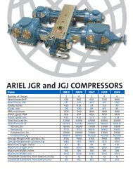
The location of the throws and the data shown on the Information Plates is very important<br />
when communicating questions concerning an Ariel compressor.<br />
#2<br />
#4<br />
#6<br />
Engine/Motor<br />
Auxiliary End<br />
FIGURE 1-1: TYPICAL COMPRESSOR THROW NUMBERING AND INFORMATION PLATE LOCATION<br />
11/01 PAGE 1 - 1<br />
#1<br />
#3<br />
#5<br />
Information Plate
FOR MODELS: JG AND JGA SECTION 1 - DESIGN SPECIFICATIONS & DATA<br />
Specifications<br />
Table 1-1: JG/JGA FRAME SPECIFICATIONS a<br />
a. For more details see Ariel Databook.<br />
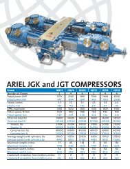
FIGURE 1-2: AUXILIARY END VIEW<br />
6<br />
MODEL JG/2 JG/4 JGA/2 JGA/4 JGA/6<br />
Stroke, inches (mm), Nominal 3.5 (89) 3.5 (89) 3 (76) 3 (76) 3 (76)<br />
Speed, RPM 750 To 1500 750 To 1500 900 To 1800 900 To 1800 900 To 1800<br />
Piston Speed, FPM (m/s) To 875 (4.45) To 875 (4.45) To 900 (4.57) To 900 (4.57) To 900 (4.57)<br />
Number of Throws 2 4 2 4 6<br />
Horsepower (kW) To 252 (188) To 504 (376) To 280 (209) To 560 (418) To 840 (626)<br />
Height - Bottom to Crankshaft 6, in.<br />
(mm)<br />
10.25 (260) - Nominal<br />
Connecting Rod To 6, in. (mm) 8.25 (210) - Nominal<br />
Maximum Width, in. (mm) 80 (2030) 80 (2030) 80 (2030) 80 (2030) 80 (2030)<br />
Maximum Length, in. (mm) 35 (890) 61 (1550) 35 (890) 61 (1550) 89 (2260)<br />
Approximate Weight<br />
2200 4700 2200 4700 7400<br />
with Cylinders, lb. (kg)<br />
(1000) (2100) (1000) (2100) (3400)<br />
Frame Oil Flow Rate @ Max. Rated 2.0<br />
5.0<br />
2.0<br />
5.0<br />
7.5<br />
Speed & 180°F (82°C), GPM (L/s) (0.13) (0.32) (0.13) (0.32) (0.47)<br />
Oil Heat Rejection, BTU/hr. (kW) 4000 (1.2) 7000 (2.1) 5000 (1.5) 8000 (2.3) 11,000 (3.2)<br />
Oil Sump Volume, US gallons (L) 4 (15) 10 (38) 4 (15) 10 (38) 16 (61)<br />
Piston Rod Diameter, in. (mm) 1.125 (29) - Nominal<br />
Internal Rod Load - Double Acting:<br />
Compression + Tension, lbf. (kN) 18,000 (80) 18,000 (80) 20,000 (89) 20,000 (89) 20,000 (89)<br />
Tension, lbf. k(N) 9000 (40) 9000 (40) 10,000 (44) 10,000 (44) 10,000 (44)<br />
Compression, lbf. (kN) 10,000 (44) 10,000 (44) 11,000 (49) 11,000 (49) 11,000 (49)<br />
Internal Rod Load - Single Acting:<br />
Tension, lbf. (kN) 9000 (40) 9000 (40) 10,000 (44) 10,000 (44) 10,000 (44)<br />
PAGE 1 - 2 11/01
FOR MODELS: JG AND JGA SECTION 1 - DESIGN SPECIFICATIONS & DATA<br />
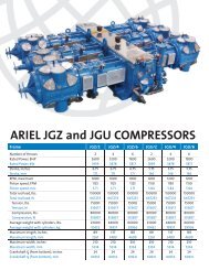
Product Information and Safety Plates<br />
FIGURE 1-3: TOP COVER<br />
Top Cover<br />
Direction of Rotation<br />
arrow plate, located at<br />
the drive end<br />
ARIEL LOGO NAME<br />
PLATE AND ADDRESS<br />
Information plate: Ariel Compressor<br />
Frame Model, Frame<br />
Serial Number, Stroke length,<br />
Maximum and Minimum Rated<br />
Speed - revolutions per<br />
minute, Maximum Rod Load -<br />
Tension and Compression,<br />
Ariel Shipping Date, Normal<br />
Lube Oil Pressure, Maximum<br />
Lube Oil Temperature, and<br />
Lube Oil Pressure Shutdown<br />
Setting. Maximum unit speed<br />
is maximum name plate rated<br />
speed or cylinder speed,<br />
whichever is the lessor. Consult<br />
Ariel Technical Manual<br />
before placing unit in operation<br />
or performing maintenance.<br />
IMPORTANT SAFETY INFOR-<br />
MATION PLATES See Page 1-4<br />
Oil Filter Plate with installation<br />
instructions. (See Page<br />
4-25)<br />
11/01 PAGE 1 - 3
FOR MODELS: JG AND JGA SECTION 1 - DESIGN SPECIFICATIONS & DATA<br />
Important Safety Information<br />
!<br />
CAUTION<br />
SEVERE PERSONAL INJURY AND PROPERTY DAMAGE<br />
CAN RESULT IF PRESSURE SYSTEM IS NOT<br />
COMPLETELY VENTED BEFORE LOOSENING THE<br />
BOLTS ON FLANGES, HEADS, VALVE CAPS, OR<br />
PACKING. CONSULT ARIEL TECHNICAL MANUAL<br />
BEFORE PERFORMING ANY MAINTENANCE.<br />
!<br />
CAUTION<br />
SEVERE PERSONAL INJURY AND PROPERTY DAMAGE<br />
WILL RESULT IF SUCTION AND DISCHARGE VALVES<br />
ARE NOT INSTALLED IN THEIR PROPER LOCATION.<br />
!<br />
CAUTION<br />
NOISE GENERATED BY RECIPROCATING MACHINERY<br />
CAN BE A SOURCE FOR HEARING INJURY. SEE<br />
PACKAGER’S INFORMATION FOR ANY SPECIFIC<br />
RECOMMENDATIONS. WEAR HEARING PROTECTION<br />
WHEN UNIT IS RUNNING.<br />
!<br />
CAUTION<br />
HOT GAS TEMPERATURES ESPECIALLY THE CYLINDER<br />
DISCHARGE AREAS, 190°F (88°C) OIL AND HIGH<br />
FRICTION AREAS CAN BE A SOURCE FOR BURNS.<br />
WEAR PROPER INSULATION WHEN WORKING AROUND<br />
THESE AREAS. SHUT DOWN UNIT AND ALLOW TO COOL<br />
BEFORE DOING MAINTENANCE IN THESE AREAS.<br />
PAGE 1 - 4 11/01
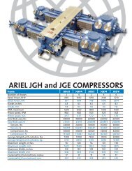
FOR MODELS: JG AND JGA SECTION 1 - DESIGN SPECIFICATIONS & DATA<br />
Distribution<br />
Block Part<br />
Number<br />
Throw<br />
Number<br />
Increase<br />
Pump<br />
Stroke<br />
FIGURE 1-4: FORCE FEED LUBRICATOR PUMP - TYPICAL<br />
Force Feed Lubricator<br />
Data Plate for Twin<br />
Pumps - Indicator Cycle<br />
Time:<br />
Normal<br />
(Seconds/cycle)<br />
Break In<br />
(Seconds/cycle)<br />
Break In<br />
Normal<br />
Increase<br />
Pump<br />
Stroke<br />
FIGURE 1-5: FORCE FEED LUBRICATOR DATA PLATES<br />
Data Plate<br />
Force Feed Lubricator<br />
Data Plate for Single<br />
Pump - Indicator Cycle<br />
Time:<br />
Distribution Block<br />
Part Number<br />
Indicator Pin<br />
Cycle Time<br />
Seconds/cycle<br />
The Force Feed Lubricator provides oil to the piston rod packing and the compressor pistons.<br />
The Lubricator Plate gives directions for adjusting the flow of oil. If this plate is missing,<br />
please contact Ariel Corporation, Mount Vernon, Ohio for a replacement or directions.<br />
NOTE: THE FORCE FEED LUBRICATOR BOX CONTAINS APPROXIMATELY 1/3 GAL-<br />
LONS (1 L) OF LUBRICANT.<br />
11/01 PAGE 1 - 5
FOR MODELS: JG AND JGA SECTION 1 - DESIGN SPECIFICATIONS & DATA<br />
Unloader Identification Plate:<br />
Customer Work Order Number,<br />
Hydrotest Pressure and Tester’s<br />
Personal Stamp are stamped<br />
near this plate on top of the<br />
Unloader body.<br />
Frame Serial Number:<br />
stamped on machined surface<br />
above the Mechanical<br />
Inspector’s Plate. On drive<br />
end throw #2 side.<br />
Discharge Valve<br />
Pocket Identification<br />
plate<br />
FIGURE 1-6: IDENTIFICATION PLATES - TYPICAL<br />
Cylinder Identification Plate - See<br />
Figure 1-7: on page 1-7<br />
Suction Valve<br />
Pocket Identification<br />
Plate<br />
Serial Number, MAWP, Part<br />
Number, Work Order Number,<br />
Hydrostatic Test Pressure, Test<br />
Date and Tester’s Personal<br />
Stamp are stamped on the end<br />
of each cylinder<br />
Cylinder Identification Plates appear on each cylinder. The serial number is also stamped on<br />
the end of each cylinder. If any plate is missing, please contact Ariel Corporation, Mount<br />
Vernon, Ohio for a replacement or specific directions.<br />
NOTE: USE THE CYLINDER AND FRAME SERIAL NUMBERS IN ALL CORRESPON-<br />
DENCE.<br />
PAGE 1 - 6 11/01
FOR MODELS: JG AND JGA SECTION 1 - DESIGN SPECIFICATIONS & DATA<br />
Nominal Cylinder<br />
Bore Diameter<br />
Stroke<br />
Length<br />
Maximum Allowable<br />
Working Pressure<br />
(Maximum Relief<br />
Valve Setting)<br />
Piston End<br />
Clearance<br />
Minimum Volumetric Clearance<br />
Percentage:<br />
VVCP (Variable<br />
Volume Clearance<br />
Pocket - Head End)<br />
Unloader Serial<br />
Number<br />
Base Volume -<br />
Additional Fixed<br />
Clearance with<br />
Pocket in the<br />
Closed Position<br />
VVCP Maximum<br />
Allowable Working<br />
Pressure<br />
CYLINDER IDENTIFICATION PLATE:<br />
Ariel Cylinder<br />
Serial Number<br />
UNLOADER IDENTIFICATION PLATE:<br />
Total Travel<br />
Distance<br />
Head End<br />
or Total Number<br />
of Turns<br />
FIGURE 1-7: CYLINDER AND UNLOADER IDENTIFICATION PLATES<br />
Cylinder<br />
Class<br />
Maximum Cylinder<br />
Rated Speed -<br />
Crankshaft Revolutions<br />
per Minute<br />
Crank End<br />
Nominal Compressor<br />
Cylinder Bore Diameter<br />
Maximum Variable<br />
Volume (at the Fully<br />
Open Position)<br />
11/01 PAGE 1 - 7
FOR MODELS: JG AND JGA SECTION 1 - DESIGN SPECIFICATIONS & DATA<br />
Clearances<br />
TABLE 1-2: CLEARANCES<br />
DESCRIPTION<br />
CLEARANCE,<br />
IN.<br />
CLEARANCE,<br />
(mm)<br />
Crankshaft Dust Seal (Feeler Gauge - Centered) 0.008 to 0.010 (0.20 to 0.25)<br />
Crankshaft Thrust (End) 0.0035 to 0.011 (0.089 to 0.28)<br />
Crankshaft Journal Bearing (Jack) 0.0005 to 0.0035 (0.013 to 0.089)<br />
Crankshaft Pin to Connecting Rod Bearing (Jack) 0.0015 to 0.0040 (0.038 to 0.102)<br />
Connecting Rod Thrust (Side) 0.007 to 0.016 (0.18 to 0.41)<br />
Connecting Rod Bushing to Crosshead Pin 0.0014 to 0.0031 (0.036 to 0.079)<br />
Crosshead Bushing to Crosshead Pin 0.0014 to 0.0036 (0.036 to 0.091)<br />
Crosshead (Bronze) to Crosshead Pin 0.0015 to 0.0025 (0.038 to 0.064)<br />
Crosshead (Babbitted Ductile Iron) to Guide - (Feeler Gaugea )<br />
0.004 to 0.008 (0.10 to 0.20)<br />
Crosshead (Babbitted Bronze) to Guide (Feeler Gauge a ) 0.006 to 0.010 (0.15 to 0.25)<br />
Total Piston End Clearance - Double Acting b<br />
0.090 to 0.145 (2.29 to 3.68)<br />
Piston End Clearance - Crank End - Double Acting b 0.035 (0.89)<br />
Piston End Clearance - Head End - Double Acting b 0.055 to 0.110 (1.40 to 2.79)<br />
Total Piston End Clearance - Tandem b,c<br />
0.090 to 0.180 (2.29 to 4.57)<br />
Piston End Clearance - Crank End Tandem b,c 0.035 (0.89)<br />
Piston End Clearance - Head End Tandem b,c 0.055 to 0.145 (1.40 to 3.68)<br />
Maximum Acceptable Piston Rod Run Out<br />
Readings d<br />
Vertical 0.0010 (0.025)<br />
Horizontal 0.0005 (0.013)<br />
a. Crosshead guide to crosshead clearance at the top is to be checked by inserting a standard 0.5 inch (13 mm) wide feeler stock<br />
from one side edge of the crosshead across to the opposite side. This is to be done at both ends. The bottom clearance is to be<br />
checked with 0.0015 inch (0.038 mm) feeler stock at the 4 corners. If the feeler can be inserted more than 0.5 inches (13 mm),<br />
the assembly is not acceptable.<br />
b. If piston end clearance is not within table tolerance, crank end + head end, contact Packager or Ariel.<br />
c. For 2-1/4P-CE cylinders, it is not practical to use CE clearance tool to set piston clearance. See “Piston and Rod - Installation” on<br />
page 5-20.<br />
d. See “Piston Rod Run Out” on page 5-21.<br />
NOTE: MEASURED CLEARANCES WILL NOT NECESSARILY AGREE BECAUSE OF<br />
OIL FILMS, ASSEMBLY TOLERANCES, WEAR, ETC. PLASTIGAGES, SOL-<br />
DER, ETC. ARE NOT TO BE USED.<br />
PAGE 1 - 8 11/01
FOR MODELS: JG AND JGA SECTION 1 - DESIGN SPECIFICATIONS & DATA<br />
Piston Ring and Packing Ring Side Clearance, Inches (mm)<br />
The standard side clearance in inches (mm) for JG and JGA compressor piston rings and<br />
packing rings when new are as follows:<br />
TABLE 1-3: NEW CONVENTIONAL PISTON RING SIDE CLEARANCE, INCHES (mm)<br />
NOMINAL<br />
WIDTH<br />
ACTUAL GROOVE<br />
WIDTH<br />
NON-METALLIC BRONZE<br />
3/16 (4.76) 0.187 to 0.189 (4.75 to 4.80) 0.005 to 0.009 (0.13 to 0.23) 0.004 to 0.008 (0.10 to 0.20)<br />
1/4 (6.35) 0.250 to 0.252 (6.35 to 6.40) 0.005 to 0.009 (0.13 to 0.23) 0.004 to 0.008 (0.10 to 0.20)<br />
5/16 (7.94) 0.312 to 0.314 (7.92 to 7.98) 0.006 to 0.010 (0.15 to 0.25) 0.004 to 0.008 (0.10 to 0.20)<br />
3/8 (9.53) 0.375 to 0.377 (9.53 to 9.58) 0.007 to 0.011 (0.18 to 0.28) 0.004 to 0.008 (0.10 to 0.20)<br />
3/4 (19.05) 0.750 to 0.752 (19.05 to 19.10) 0.014 to 0.019 (0.36 to 0.48) 0.006 to 0.010 (0.15 to 0.25)<br />
TABLE 1-4: NEW RIDER RING SIDE CLEARANCE, INCHES (mm)<br />
NOMINAL WIDTH ACTUAL GROOVE WIDTH<br />
3/16 (4.76) 0.187 to 0.189 (4.75 to 4.80)<br />
1/4 (6.35) 0.250 to 0.252 (6.35 to 6.40)<br />
3/8 (9.53) 0.375 to 0.377 (9.53 to 9.58)<br />
1/2 (12.70) 0.500 to 0.502 (12.70 to 12.75)<br />
TABLE 1-5: PACKING RING SIDE CLEARANCE, INCHES (mm)<br />
ACTUAL<br />
GROOVE<br />
WIDTH<br />
0.375 to 0.377<br />
(9.53 to 9.58)<br />
0.447 to 0.449<br />
(11.35 to 11.41)<br />
0.562 to 0.564<br />
(14.28 to 14.33)<br />
0.936 to 0.938<br />
(23.77 to 23.82)<br />
a. Side loaded “AL” (5) ring type<br />
1 - RING/<br />
GROOVE<br />
NON-METAL OR<br />
CI<br />
0.011 to 0.014<br />
(0.28 to 0.36)<br />
2 - RINGS/<br />
GROOVE<br />
NON-METAL OR<br />
CI<br />
0.011 to 0.015<br />
(0.28 to 0.38)<br />
3 - RINGS/<br />
GROOVE<br />
NON-METAL &<br />
CI<br />
N/A N/A 0.013 to 0.018<br />
(0.33 to 0.46)<br />
N/A N/A 0.017 to 0.022<br />
(0.43 to 0.56)<br />
N/A Zero (0) a<br />
BRONZE<br />
N/A 0.006 to 0.008<br />
(0.15 to 0.20)<br />
11/01 PAGE 1 - 9<br />
N/A
FOR MODELS: JG AND JGA SECTION 1 - DESIGN SPECIFICATIONS & DATA<br />
TABLE 1-6: PISTON TO BORE CLEARANCE AND CONVENTIONAL PISTON RING END GAP,<br />
INCHES (mm) - LUBRICATED M, P & SP CLASS CYLINDERS<br />
BORE<br />
DIAMETER A<br />
PISTON TO BORE<br />
CLEARANCE<br />
PISTON RING END GAP - NON-METALLIC<br />
NEW MAXIMUM<br />
2.0625 (52) 0.007 to 0.011 (0.18 to 0.28) 0.025 to 0.030 (0.64 to 0.76) 0.120 (3.05)<br />
2.25 (57) 0.007 to 0.011 (0.18 to 0.28) 0.027 to 0.032 (0.69 to 0.81) 0.128 (3.18)<br />
2.5 (64) 0.007 to 0.011 (0.18 to 0.28) 0.030 to 0.036 (0.76 to 0.91) 0.144 (3.66)<br />
2.75 (70) 0.007 to 0.011 (0.18 to 0.28) 0.033 to 0.040 (0.84 to 1.02) 0.160 (3.71)<br />
3 (76) 0.007 to 0.011 (0.18 to 0.28) 0.036 to 0.044 (0.91 to 1.12) 0.176 (4.47)<br />
3.25 (83)) 0.009 to 0.013 (0.23 to 0.33) 0.039 to 0.047 (0.99 to 1.19) 0.188 (4.76)<br />
3.5 (89) 0.009 to 0.013 (0.23 to 0.33) 0.042 to 0.052 (1.07 to 1.30) 0.208 (5.28)<br />
3.75 (95) 0.010 to 0.014 (0.25 to 0.36) 0.046 to 0.056 (0.17 to 1.42) 0.224 (5.69)<br />
3.875 (98) 0.010 to 0.014 (0.25 to 0.36) 0.047 to 0.057 (0.19 to 1.45) 0.228 (5.79)<br />
4.125 (105) 0.010 to 0.014 (0.25 to 0.36) 0.049 to 0.060 (1.24 to 1.52) 0.240 (6.10)<br />
4.375 (111) 0.011 to 0.015 (0.28 to 0.38) 0.052 to 0.064 (1.32 to 1.63) 0.255 (6.48)<br />
4.75 (121) 0.012 to 0.017 (0.30 to (0.43) 0.057 to 0.077 (1.45 to 1.96) 0.308 (7.82)<br />
5.125 (130) 0.012 to 0.017 (0.30 to 0.43) 0.061 to 0.081 (1.55 to 2.06) 0.324 (8.23)<br />
5.5 (140) 0.013 to 0.018 (0.33 to 0.46) 0.065 to 0.085 (1.65 to 2.16) 0.340 (8.64)<br />
5.75 (146) 0.013 to 0.018 (0.33 to 0.46) 0.068 to 0.088 (1.73 to 2.24) 0.352 (8.94)<br />
6.125 (156) 0.014 to 0.020 (0.36 to 0.51) 0.073 to 0.093 (1.85 to 2.36) 0.372 (9.45)<br />
6.5 (165) 0.014 to 0.020 (0.36 to 0.51) 0.077 to 0.097 (1.96 to 2.46) 0.388 (9.86)<br />
7.5 (191) 0.016 to 0.022 (0.41 to 0.56) 0.089 to 0.109 (2.26 to 2.77) 0.430 (10.92)<br />
8 (203) 0.016 to 0.022 (0.41 to 0.56) 0.095 to 0.115 (2.41 to 2.87) 0.460 (11.68)<br />
a. Conventional piston rings are standard for all M, P and SP Class Cylinders, except for 1-3/4M-FS Class Cylinder with bore<br />
diameters of 1.625” (41mm) and 1.75” (44) where piston/rider rings are standard. Piston/rider rings are optional for all<br />
other lubricated M, P and SP Class Cylinders. See Table 1-8.<br />
Table 1-7: PISTON TO BORE CLEARANCE AND CONVENTIONAL PISTON RING END GAP, INCHES<br />
(mm) - NON-LUBE a M & P CLASS CYLINDERS<br />
BORE<br />
DIAMETER<br />
a. With Wear Bands.<br />
PISTON TO BORE<br />
CLEARANCE<br />
PISTON RING END GAP - NON-METALLIC<br />
NEW MAXIMUM<br />
2.75 (70) 0.057 to 0.064 (1.45 to 1.63) 0.033 to 0.045 (0.84 to 1.14) 0.180 (4.57)<br />
PAGE 1 - 10 11/01
FOR MODELS: JG AND JGA SECTION 1 - DESIGN SPECIFICATIONS & DATA<br />
TABLE 1-8: PISTON TO BORE CLEARANCE AND PISTON/RIDER RING END GAP, INCHES (mm) -<br />
LUBRICATED M, P & SP CLASS CYLINDERS.<br />
BORE<br />
DIAMETERa PISTON TO BORE<br />
PISTON/RIDER RING END GAP<br />
CLEARANCE<br />
NEW MAXIMUM<br />
1.625 (41) 0.090 to 0.096 (2.29 to 2.44)<br />
1.75 (44) 0.090 to 0.096 (2.29 to 2.44) 0.016 to 0.032 (0.41 to 0.81) 0.128 (3.25)<br />
2.0625 (52) 0.090 to 0.096 (2.29 to 2.44) 0.020 to 0.036 (0.51 to 0.91) 0.144 (3.66)<br />
2.25 (57) 0.090 to 0.096 (2.29 to 2.44) 0.023 to 0.039 (0.58 to 0.99) 0.156 (3.96)<br />
2.5 (64) 0.090 to 0.096 (2.29 to 2.44) 0.044 to 0.060 (1.12 to 1.52 0.240 (6.10)<br />
2.75 (70) 0.090 to 0.096 (2.29 to 2.44) 0.044 to 0.060 (1.12 to 1.52 0.240 (6.10)<br />
3 (76) 0.090 to 0.096 (2.29 to 2.44) 0.044 to 0.060 (1.12 to 1.52 0.240 (6.10)<br />
3.25 (83)) 0.090 to 0.096 (2.29 to 2.44) 0.044 to 0.060 (1.12 to 1.52 0.240 (6.10)<br />
3.5 (89) 0.090 to 0.096 (2.29 to 2.44) 0.044 to 0.060 (1.12 to 1.52 0.240 (6.10)<br />
3.75 (95) 0.090 to 0.096 (2.29 to 2.44) 0.044 to 0.060 (1.12 to 1.52 0.240 (6.10)<br />
3.875 (98) 0.090 to 0.096 (2.29 to 2.44) 0.045 to 0.061 (1.14 to 1.55) 0.244 (6.20)<br />
4.125 (105) 0.090 to 0.096 (2.29 to 2.44) 0.049 to 0.065 (1.24 to 1.65) 0.260 (6.60)<br />
4.375 (111) 0.090 to 0.096 (2.29 to 2.44) 0.052 to 0.068 (1.32 to 1.73) 0.272 (6.91)<br />
4.75 (121) 0.090 to 0.096 (2.29 to 2.44) 0.057 to 0.073 (1.45 to 1.85) 0.292 (7.42)<br />
5.125 (130) 0.090 to 0.096 (2.29 to 2.44) 0.062 to 0.078 (1.57 to 1.98) 0.312 (7.93)<br />
5.5 (140) 0.090 to 0.096 (2.29 to 2.44) 0.068 to 0.084 (1.73 to 2.13) 0.336 (8.53)<br />
5.75 (146) 0.090 to 0.096 (2.29 to 2.44) 0.071 to 0.087 (1.80 to 2.21) 0.348 (8.84)<br />
6.125 (156) 0.090 to 0.096 (2.29 to 2.44) 0.069 to 0.099 (1.75 to 2.51) 0.396 (10.06)<br />
6.5 (165) 0.090 to 0.096 (2.29 to 2.44) 0.074 to 0.104 (1.88 to 2.64) 0.416 (10.57)<br />
7.5 (191) 0.090 to 0.096 (2.29 to 2.44) b<br />
b<br />
8 (203) 0.090 to 0.096 (2.29 to 2.44) b b<br />
a. Conventional piston rings are standard for all M, P and SP Class Cylinders, except for 1-3/4M-FS Class Cylinder with<br />
bore diameters of 1.625” (41mm) and 1.75” (44) where piston/rider rings are standard. Piston/rider rings are optional for<br />
all other lubricated M, P and SP Class Cylinders.<br />
b. 8M x 3-1/2” (88.9 mm) stroke & 8SP-HE class cylinders, w/ 7.5” (191) bore: end gap, new is 0.099” to 0.129” (2.51 to<br />
3.53), maximum is 0.516” (13.11).<br />
8M x 3” (76.2) stroke, w/ 7.5” (191) bore: new 0.088” to 0.118” (2.24 to 3.00), maximum 0.472” (11.99).<br />
8M x 3-1/2” (88.9) & 8SP-HE, w/ 8” (203) bore: new 0.106” to 0.136” (2.69 to 3.43), maximum 0.544” (14.07).<br />
8M x 3” (76.2) w/ 8” (203) bore: new 0.095” to 0.125” (2.41 to 3.18), maximum 0.500” (12.70).<br />
11/01 PAGE 1 - 11
FOR MODELS: JG AND JGA SECTION 1 - DESIGN SPECIFICATIONS & DATA<br />
TABLE 1-9: PISTON TO BORE CLEARANCE AND CONVENTIONAL PISTON RING END GAP<br />
(ANGULAR-CUT & SEAL-JOINT), INCHES (mm) - LUBRICATED JG CLASS CYLINDERS<br />
BORE<br />
DIAMETER<br />
a<br />
PISTON TO BORE<br />
CLEARANCE<br />
PISTON RING END GAP - NON-<br />
METALLIC b<br />
NEW MAXIMUM<br />
1.25 (32) c 0.025 to 0.033 (0.64 to 0.84) 0.018 to 0.028 (0.46 to 0.71) 0.112 (2.85)<br />
1.5 (38) b 0.030 to 0.038 (0.76 to 0.97) 0.021 to 0.031 (0.51 to 0.79) 0.124 (3.15)<br />
1.625 (41) b 0.030 to 0.038 (0.76 to 0.97) 0.023 to 0.033 (0.58 to 0.84) 0.132 (3.35)<br />
1.75 (44) b 0.030 to 0.038 (0.76 to 0.97) 0.025 to 0.035 (0.64 to 0.89) 0.140 (3.55)<br />
2.75 (70) 0.009 to 0.014 (0.23 to 0.36) 0.028 to 0.040 (0.71 to 1.02) 0.160 (4.06)<br />
3 (76) 0.009 to 0.014 (0.23 to 0.36) 0.030 to 0.036 (0.76 to 0.91) 0.144 (3.66)<br />
3.375 (86) 0.010 to 0.015 (0.25 to 0.38) 0.034 to 0.041 (0.88 to 1.04) 0.164 (4.17)<br />
3.625 (92) 0.010 to 0.015 (0.25 to 0.38) 0.036 to 0.044 (0.91 to 1.12) 0.176 (4.47)<br />
3.875 (98) 0.011 to 0.016 (0.28 to 0.41) 0.039 to 0.057 (0.99 to 1.30) 0.228 (5.79)<br />
4.125 (105) 0.011 to 0.016 (0.28 to 0.41) 0.041 to 0.050 (1.04 to 1.27) 0.200 (5.08)<br />
4.75 (121) 0.012 to 0.018 (0.30 to 0.46) 0.057 to 0.077 (1.45 to 1.96) 0.308 (7.82)<br />
5.125 (130) 0.012 to 0.018 (0.30 to 0.46) 0.061 to 0.081 (1.55 to 2.06) 0.324 (8.23)<br />
6.125 (156) 0.013 to 0.019 (0.33 to 0.48) 0.073 to 0.093 (1.85 to 2.36) 0.372 (9.45)<br />
6.5 (165) 0.014 to 0.020 (0.36 to 0.51) 0.077 to 0.097 (1.96 to 2.46) 0.388 (9.86)<br />
7.125 (181) 0.015 to 0.021 (0.38 to 0.53) 0.085 to 0.105 (2.16 to 2.67) 0.409 (10.4)<br />
7.5 (191) 0.015 to 0.021 (0.38 to 0.53) d 0.089 to 0.109 (2.26 to 2.77) 0.430 (10.9)<br />
8.5 (216) 0.017 to 0.023 (0.43 to 0.58) 0.102 to 0.122 (2.59 to 3.10) 0.488 (12.4)<br />
8.875 (225) 0.018 to 0.024 (0.46 to 0.61) 0.106 to 0.126 (2.69 to 3.20) 0.504 (12.8)<br />
10.5 (267) 0.022 to 0.027 (0.56 to 0.69) 0.125 to 0.145 (3.18 to 3.68) 0.580 (14.7)<br />
11 (279) 0.022 to 0.028 (0.56 to 0.71) 0.131 to 0.151 (3.33 to 3.84) 0.604 (15.3)<br />
a. Conventional piston rings are standard for JG Class Cylinders, except 2-1/2JG-FS-HE Class cylinders with<br />
bore diameters of 2.25” (57mm) & 2.5” (64); 3JG-CE, 2.75” (70) & 3” (76); 3-5/8JG-CE, 3.375” (86) &<br />
3.625” (92); and 13-12JG, 13” (330) & 13.5” (343), which use piston/rider rings. Piston/rider rings are<br />
optional for other lubricated JG Cylinders, except for the 1-3/4JG-FS-HE class, which uses conventional<br />
type rings but with seal-joint (see Figure 5-12: on page 5-23) and wear band.<br />
b. Seal-Joint piston rings are standard for JG Class high-pressure tandem cylinders.<br />
c. The 1-3/4JG-FS-HE class bore diameter sizes use conventional type seal-ring piston rings and wear band,<br />
see Table 1-11 for wear band values.<br />
d. The the 7.5” (191 mm) bore with a heavy piston, the piston to bore clearance is 0.085 to 0.098” (2.16 to<br />
2.49 mm).<br />
PAGE 1 - 12 11/01
FOR MODELS: JG AND JGA SECTION 1 - DESIGN SPECIFICATIONS & DATA<br />
TABLE 1-10: PISTON TO BORE CLEARANCE AND CONVENTIONAL PISTON RING END GAP, INCHES<br />
(mm) - NON-LUBE JG CLASS CYLINDERS<br />
BORE<br />
DIAMETER<br />
PISTON TO BORE<br />
CLEARANCE<br />
PISTON RING END GAP - NON-METALLIC<br />
NEW MAXIMUM<br />
3.375 (86) 0.075 to 0.083 (1.91 to 2.110 0.044 to 0.056 (1.12 to 1.42) 0.224 (5.68)<br />
6.125 (156) 0.084 to 0.097 (2.13 to 2.46) 0.073 to 0.093 (1.85 to 2.36) 0.373 (9.44)<br />
7.5 (191) 0.085 to 0.098 (2.16 to 2.49) 0.098 to 0.118 (2.49 to 3.00) 0.472 (12.00)<br />
TABLE 1-11: WEAR BAND END GAP, RADIAL PROJECTION & SIDE CLEARANCE (NEW) - LUBRICATED<br />
1-3/4JG-FS-HE & 7-1/2JG (WITH HEAVY PISTON) CLASS, INCHES (mm)<br />
BORE<br />
DIAMETER<br />
END GAP<br />
MINIMUM<br />
a. Replace wear band before piston contacts the cylinder bore.<br />
RADIAL PROJECTION a<br />
SIDE CLEARANCE<br />
1.25 (32) 0.039 (0.99) 0.005 to 0.012 (0.13 to 0.30) 0.010 to 0.014 (0.25 to 0.36)<br />
1.5 (38) 0.049 (1.24) 0.0075 to 0.0145 (0.19 to<br />
0.37)<br />
0.010 to 0.014 (0.25 to 0.36)<br />
1.625 (41) 0.052 (1.32) 0.0075 to 0.0135 (0.19 to<br />
0.34)<br />
0.010 to 0.014 (0.25 to 0.36)<br />
1.75 (44) 0.058 (1.47) 0.0075 to 0.0145 (0.19 to<br />
0.37)<br />
0.010 to 0.014 (0.25 to 0.36)<br />
7.5 (191) 0.210 (5.33) 0.028 to 0.039 (0.71 to 0.99) 0.011 to 0.016 (0.28 to 0.41)<br />
TABLE 1-12: WEAR BAND END GAP, RADIAL PROJECTION & SIDE CLEARANCE (NEW) - NON-LUBE,<br />
INCHES (mm)<br />
BORE<br />
DIAMETER<br />
END GAP<br />
MINIMUM<br />
a. Replace wear band before piston contacts the cylinder bore.<br />
RADIAL PROJECTION a<br />
SIDE CLEARANCE<br />
2.75 (70)) 0.088 (0.2.24)) 0.036 to 0.050 (0.91 to 1.27) 0.010 to 0.014 (0.25 to 0.36)<br />
3.375 (86) 0.085 (2.16) 0.027 to 0.034 (0.69 to 0.86) 0.010 to 0.014 (0.25 to 0.36)<br />
6.125 (156) 0.201 (5.11) 0.028 to 0.039 (0.71 to 0.99) 0.010 to 0.014 (0.25 to 0.36)<br />
7.5 (191) 0.164 (4.17) 0.028 to 0.039 (0.71 to 0.99) 0.011 to 0.016 (0.28 to 0.41)<br />
11/01 PAGE 1 - 13
FOR MODELS: JG AND JGA SECTION 1 - DESIGN SPECIFICATIONS & DATA<br />
TABLE 1-13: PISTON TO BORE CLEARANCE AND PISTON/RIDER RING END GAP (ANGULAR-CUT),<br />
INCHES (mm) - LUBRICATED JG CLASS CYLINDERS<br />
BORE<br />
DIAMETER a<br />
PISTON TO BORE<br />
CLEARANCE<br />
PISTON/RIDER RING END GAP<br />
NEW MAXIMUM<br />
2.25 (57) 0.090 to 0.096 (2.29 to 2.44) 0.023 to 0.039 (0.58 to 0.99 0.156 (3.96)<br />
2.5 (64) 0.090 to 0.096 (2.29 to 2.44) 0.030 to 0.046 (0.76 to 1.17) 0.184 (4.67)<br />
2.75 (70) 0.090 to 0.096 (2.29 to 2.44) 0.044 to 0.060 (1.12 to 1.52) 0.240 (6.10)<br />
3 (76) 0.090 to 0.096 (2.29 to 2.44) 0.044 to 0.060 (1.12 to 1.52) 0.240 (6.10)<br />
3.375 (86) 0.090 to 0.096 (2.29 to 2.44) 0.044 to 0.060 (1.12 to 1.52) 0.240 (6.10)<br />
3.625 (92) 0.090 to 0.096 (2.29 to 2.44) 0.044 to 0.060 (1.12 to 1.52) 0.240 (6.10)<br />
3.875 (98) 0.090 to 0.096 (2.29 to 2.44) 0.051 to 0.067 (1.30 to 1.70) 0.268 (6.81)<br />
4.125 (105) 0.090 to 0.096 (2.29 to 2.44) 0.055 to 0.071) (1.40 to 1.80) 0.284 (7.21)<br />
4.75 (121) 0.090 to 0.096 (2.29 to 2.44) 0.057 to 0.073 (1.45 to 1.85) 0.292 (7.42)<br />
5.125 (130) 0.090 to 0.096 (2.29 to 2.44) 0.062 to 0.078 (1.57 to 1.98) 0.312 (7.93)<br />
6.125 (156) 0.090 to 0.096 (2.29 to 2.44) 0.069 to 0.099 (1.75 to 2.51) 0.396 (10.1)<br />
6.5 (165) 0.090 to 0.096 (2.29 to 2.44) 0.074 to 0.104 (1.88 to 2.64) 0.416 (10.6)<br />
7.125 (181) 0.090 to 0.096 (2.29 to 2.44) 0.083 to 0.113 (2.11 to 2.87) 0.452 (11.5)<br />
7.5 (191) 0.090 to 0.096 (2.29 to 2.44) 0.088 to 0.118 (2.24 to 3.00) 0.472 (12.0)<br />
8.5 (216) 0.090 to 0.096 (2.29 to 2.44) 0.114 to 0.144 (2.90 to 3.66) 0.576 (14.6)<br />
8.875 (225) 0.090 to 0.096 (2.29 to 2.44) 0.120 to 0.150 (3.05 to 3.81) 0.600 (15.2)<br />
10.5 (267) 0.090 to 0.096 (2.29 to 2.44) 0.144 to 0.174 (3.66 to 4.42) 0.696 (17.7)<br />
11 (279) 0.090 to 0.096 (2.29 to 2.44) 0.152 to 0.182 (3.86 to 4.62) 0.728 (18.5)<br />
13 (330) 0.090 to 0.096 (2.29 to 2.44) 0.182 to 0.212 (4.62 to 5.38) 0.848 (21.5)<br />
13.5 (343) 0.090 to 0.096 (2.29 to 2.44) 0.190 to 0.220 (4.83 to 5.59) 0.880 (22.4)<br />
a. Conventional piston rings are standard for JG Class Cylinders, except 2-1/2JG-FS-HE Class cylinders with bore<br />
diameters of 2.25” (57mm) & 2.5” (64); 3JG-CE, 2.75” (70) & 3” (76); 3-5/8JG-CE, 3.375” (86) & 3.625” (92); and<br />
13-12JG, 13” (330) & 13.5” (343), which use piston/rider rings.<br />
Piston/rider rings are optional for other lubricated JG Cylinders, except for the 1-3/4JG-FS-HE class, which uses<br />
conventional type seal-joint rings and wear band.<br />
PAGE 1 - 14 11/01
FOR MODELS: JG AND JGA SECTION 1 - DESIGN SPECIFICATIONS & DATA<br />
Table 1-14: PISTON TO BORE CLEARANCE AND PISTON/RIDER RING END GAP (SEAL-JOINT a ),<br />
INCHES (mm) - LUBRICATED JG CLASS CYLINDERS<br />
BORE<br />
DIAMETER<br />
PISTON TO BORE<br />
CLEARANCE<br />
a. Seal-Joint piston rings are standard for JG Class high-pressure Tandem Cylinders. See Figure 5-12: on page 5-23<br />
Fastener Tightening Torque<br />
Listed in the following tables are fastener tightening torque values required for proper<br />
assembly of Ariel JG and JGA compressors. Refer to the section concerning a subject component<br />
for detailed assembly procedures.<br />
Threads must be clean and free of burrs.<br />
PISTON/RIDER RING END GAP<br />
NEW MAXIMUM<br />
2.75 (70) 0.090 to 0.096 (2.29 to 2.44) 0.047 to 0.059 (1.19 to 1.50) 0.177 (4.50)<br />
3 (76) 0.090 to 0.096 (2.29 to 2.44) 0.051 to 0.063 (1.30 to 1.60) 0.189 (4.80)<br />
Torque values are based on the use of petroleum type lubricants on both the threads and<br />
seating surfaces. Use lubricating oil or Lubriplate 630, except for compressor rods-piston<br />
end, piston nuts and crosshead nuts use Never-Seez (by Bostik, Boston St., Middleton, MA<br />
01949, phone: 508-777-0100). Molybdenum disulfide lubricants and Never-Seez are not<br />
otherwise to be used for fastener lubrication, unless specified, or excessive stresses can<br />
result with the listed values.<br />
TABLE 1-15: FASTENER TIGHTENING VALUES (for latest available information see ER-63 at www.arielcorp.com)<br />
FASTENER<br />
NOMINAL<br />
SIZE,<br />
INCH - TPI<br />
TYPE<br />
TORQUE,<br />
LB X FT (N·m)<br />
Main Bearing Cap - Cap Screw 1/2 - 13 12 Point - Grade 8 58 (79)<br />
Connecting Rod Cap - Cap Screw 1/2 - 20 12 Point - Grade 8 67 (91)<br />
Crosshead Pin Thru Bolt - Lock Nut 3/8 - 24 Hex - Prevailing 25 (34)<br />
Spacer Bar - Cap Screw 5/8 - 18 Hex Grade 9 92 (125)<br />
Crosshead Guide to Frame 1/2 - 13 12 Point 48 (65)<br />
Distance Piece to Crosshead Guide - Cap Screw 12 - 13 12 Point 57 (77)<br />
Distance Piece to Crosshead Guide (11JG) - Cap<br />
Screw<br />
3/8 - 16 Socket Head 18 (24)<br />
Crosshead Guide to Cylinder - Cap Screw 1/2 - 13 12 Point 48 (65)<br />
Eccentric Vernier Cap - Cap Screw 5/16 - 18 Hex - Grade 8 Hand Wrench Tight<br />
Idler Sprocket Thru Bolt - Lock Nut 1/2 - 20 Hex - Prevailing 41 (55)<br />
Rod Packing - Cap Screw 1/2 - 13 12 Point - Grade 8 35 (48)<br />
Piston Nut 7/8 - 12 Ariel Design 222 (300)<br />
Crosshead-Balance Nut 1 - 12 Ariel Design 255 (345)<br />
11/01 PAGE 1 - 15
FOR MODELS: JG AND JGA SECTION 1 - DESIGN SPECIFICATIONS & DATA<br />
TABLE 1-15: FASTENER TIGHTENING VALUES<br />
FASTENER<br />
NOMINAL<br />
SIZE,<br />
INCH - TPI<br />
TYPE<br />
TORQUE,<br />
LB X FT (N·m)<br />
Piston Rod Oil Slinger - Lock Nut 1/4 - 28 Jam Nut - Prevailing 96 lb x in. (11)<br />
Rupture Disk - Blow-Out Fitting Cap 1/4 Nom. Tube Hex - Tube Fitting 36 lb x in. (4.1)<br />
Frame Foot Hold Down 3/4 - 10 Hex Stud-Nut 175a (235)<br />
Crosshead Guide Support Foot Hold Down 5/8 - 11 Hex Stud-Nut 90a (120)<br />
Valve Cap/Cylinder Head/Gas Passage/<br />
Unloader - Cap Screw b<br />
3/8 - 16 Hex - Grade 8 or 9 or 193 lb x in. (22)<br />
7/16 - 14<br />
1/2 - 13<br />
12<br />
Point - Grade B7M or 8<br />
26 (35)<br />
40 (54)<br />
5/8 -11 79 (105)<br />
3/4 - 10 140 (190)<br />
7/8 - 9 230 (310)<br />
7/8 -14 260 (350)<br />
1 - 8 345 (465)<br />
Tandem Cylinder to Cylinder - Cap Screwb 1/2 - 13<br />
5/8 - 11<br />
Hex - Grade 8 or 9 or<br />
12 Point - Grade 8<br />
44 (60)<br />
88 (120)<br />
3/4 - 10 160 (215)<br />
Seating Studs in Cylinder 3/8 - 16 Dog Point 107 lb x in. (12)<br />
7/16 - 14 172 lb x in. (19)<br />
1/2 - 13 22 (30)<br />
9/16 - 12 32 (43)<br />
5/8 - 11 44 (60)<br />
3/4 - 10 79 (105)<br />
7/8 - 9 130 (170)<br />
1 - 8 190 (260)<br />
Distribution Block Tie Rod - Nut 1/4 - 28 Hex 68 lb x in. (7.7)<br />
Distribution Block Divider Valve - Screw 1/4 - 28 Socket Head 109 lb x in. (12)<br />
Grade 5 - Hex Cap Screw All Hex - Grade 5 Hand Wrench Tight<br />
a. Minimum torque for recommended hold down stud size to provide stress in stud of 55,000 psi (380 MPa). Stud must have an<br />
ultimate strength of 100,000 psi (690 MPa) or greater. If greater, increase torque to stress stud to about 55% of ultimate<br />
strength of stud material, as specified by packager.<br />
b. When studs are specified for cylinder applications, tighten stud-nuts to the same values as cap screws in similar applications.<br />
Reference Figure 1-8:<br />
PAGE 1 - 16 11/01
FOR MODELS: JG AND JGA SECTION 1 - DESIGN SPECIFICATIONS & DATA<br />
FIGURE 1-8: DOG POINT STUDS<br />
STUD<br />
11/01 PAGE 1 - 17
FOR MODELS: JG AND JGA SECTION 1 - DESIGN SPECIFICATIONS & DATA<br />
TABLE 1-16: HOERBIGER VALVE ASSEMBLY FASTENERS - TIGHTENING VALUES<br />
FASTENER<br />
NOMINAL SIZE<br />
INCH - TPI<br />
TYPE<br />
TORQUE,<br />
LB X FT (N·m)<br />
Center Cap Screwa b<br />
5/16 - 24<br />
3/8 - 24<br />
12 Point - Steel Grade<br />
8<br />
26 (35)<br />
45 (61)<br />
7/16 - 20 62 (83)<br />
5/16 - 24 12 Point- Steel Grade 5 18 (24)<br />
3/8 - 24 32 (43)<br />
7/16 - 20 50 (68)<br />
5/16 - 24 12 Point - Grade B8M - 120 lb x in. (13.6)<br />
3/8 - 24 Stainless Steel 192 lb x in. (21.7)<br />
7/16 - 20 24 (33)<br />
Center Stud - Drake Lock Nut 1/4 - 28 Bottom Half 103 lb x in. (11.6)<br />
Top Half 66 lb x in. (7.5)<br />
5/16 - 24 Bottom Half 168 lb x in. (18.9)<br />
Top Half 96 lb x in. (10.8)<br />
3/8 - 24 Bottom Half 192 lb x in. (21.7)<br />
Top Half 96 lb x in. (10.8)<br />
1/2 - 20 Bottom Half 36 (49) c<br />
Top Half 20 (27)<br />
5/8 - 18 Bottom Half 73 (99)<br />
Top Half 40 (54)<br />
3/4 - 16 Bottom Half 130 (176)<br />
Top Half 70 (95)<br />
Peripheral Cap Screws 10 - 32 Hex Socket Head 25 lb x in. (2.8)<br />
12 - 28 43 lb x in. (4.9)<br />
1/4 - 20 110 lb x in. (12.4)<br />
5/16 - 18 176 lb x in. (19.9)<br />
3/8 - 16 21 (28)<br />
a. 12 Point Cap Screw Center Fasteners in Valve Assemblies not marked SPL (Spiralock Threads), must be cleaned with<br />
Loctite Safety solvent and locked with one to two drops of Loctite #272. Do not use petroleum thread lubricants.<br />
b. 12 Point Cap Screws in Valve Assemblies with Spiralock Threads and marked SPL (see Figure 1-9:) are lubricated,<br />
both threads and seating surfaces, with a petroleum type lubricant only.<br />
c. 29 lb x ft (39 N·m) for 1/2 - 20 Bottom Half - Drake Lock Nut with non-metallic Plates in Liftwasher Type Valves.<br />
PAGE 1 - 18 11/01
FOR MODELS: JG AND JGA SECTION 1 - DESIGN SPECIFICATIONS & DATA<br />
Discharge Seat<br />
Tightening Torque Procedures<br />
Bottom Views<br />
FIGURE 1-9: SPIRALOCK THREADED VALVE ASSEMBLY - MARKED SPL<br />
TOP - LOCKING<br />
BOTTOM HALF<br />
FIGURE 1-10: DRAKE LOCK NUT<br />
Suction Guard<br />
Listed below are some procedures which make fastener tightening more accurate and will<br />
help ensure that the proper torque is being applied.<br />
1. Ensure that the torque wrench is properly calibrated and used by qualified personnel<br />
to achieve the required fastener tightening torque for all critical parts, except for<br />
the crosshead balance/lock nut which may be tightened using the “tried and true”<br />
slugging procedure.<br />
2. Always check to determine over what range the torque wrench is accurate since<br />
most torque wrenches are not accurate over their entire range.<br />
11/01 PAGE 1 - 19
FOR MODELS: JG AND JGA SECTION 1 - DESIGN SPECIFICATIONS & DATA<br />
3. Always apply a steady slow force to a torque wrench, do not jerk it. When a torque<br />
wrench is jerked the amount of torque applied can be as much as one and a half<br />
times the amount set on the wrench. For example, if a wrench is set at 80 lb x ft but<br />
is jerked, 120 lb x ft torque can be applied.<br />
4. Always do the final tightening with a torque wrench. Do not tighten the fastener with<br />
a ratchet or impact wrench and then "check" the torque with a torque wrench.<br />
5. Do not double tap a torque wrench. Rapidly double taping a torque wrench will<br />
make the torque on the bolt more than what is set by a significant amount. If it is<br />
desired to check the setting release all pressure on the wrench and then slowly<br />
apply a steady force until the click is felt.<br />
6. Always reset the torque wrench to its lowest setting when the job is complete. If the<br />
torque wrench is left in a high setting the spring in it is stressed and will become<br />
inaccurate with time. If the torque wrench is put back to its lowest setting the spring<br />
will relax and retain its accuracy.<br />
7. Do not use a torque wrench to break fasteners loose as it may overload the torque<br />
wrench and/or cause loss of calibration.<br />
8. For applications requiring the use of a boxed end or crowsfoot adapter with a torque<br />
wrench to reach not readily accessible fasteners, the torque wrench setting will not<br />
be the actual torque applied to the fastener. 1<br />
9. The ratio of actual torque at the fastener with that on the wrench scale is a function<br />
of the adapter's length and its position in relation to the torque wrench beam and<br />
the location on that at which the force is applied (see Figure 1-11:).<br />
Tw =<br />
Ta⎛<br />
L<br />
------------- ⎞<br />
⎝L + A⎠<br />
Tw = Torque wrench setting, lb x ft<br />
Ta = Torque required at fastener, lb x ft<br />
L = Length of wrench, ft (from square drive end to center point of force on handle)<br />
A = Length of adapter, ft (measured through end of adapter on a line parallel to<br />
the center line of the wrench)<br />
These are general guidelines to assist in the proper use of torque wrenches. Consult with<br />
your torque wrench dealer for more detailed information.<br />
1. The exception is when the adapter is 90° to the torque wrench. The torque will be the same as on the wrench<br />
scale (see Figure 1-12:).<br />
PAGE 1 - 20 11/01
FOR MODELS: JG AND JGA SECTION 1 - DESIGN SPECIFICATIONS & DATA<br />
Ariel Bolting<br />
FORCE<br />
FIGURE 1-11: TORQUE WRENCH WITH ADAPTOR AT ANY ANGLE<br />
FORCE<br />
FIGURE 1-12: TORQUE WRENCH WITH ADAPTOR AT RIGHT ANGLE<br />
Bolts have been selected that meet Ariel's strength, elongation, sealing and locking requirements.<br />
Proper bolting must be used and tightened to the values listed in Table 1-15 on page<br />
1-15. Figure 1-13: is provided to assist in the identification of bolts used in an Ariel compressor.<br />
Connecting rod, valve cap and suction/discharge nozzle-Ariel supplied specialized companion<br />
flange-bolting is modified to prevent fatigue and cannot be replaced with standard bolts.<br />
If attempting to replace other bolting with standard bolts and there is any question, contact<br />
your packager or Ariel. Ariel supplied replacement bolting is recommended.<br />
11/01 PAGE 1 - 21
FOR MODELS: JG AND JGA SECTION 1 - DESIGN SPECIFICATIONS & DATA<br />
Hex head Grade 5<br />
Hex head Grade 9<br />
FIGURE 1-13: BOLT IDENTIFICATION<br />
Hex head Grade 8<br />
Hex Socket Head Grade 8<br />
12 Point Grade 8 12 Point Grade B7M (NACE)<br />
12 Point Interim Grade 5 12 Point Grade 5<br />
12 Point Stainless<br />
Steel Grade B8M<br />
CAUTION: WHEN RE-ASSEMBLING OR<br />
REPLACING BOLTING, SEE THE<br />
PARTS LIST TO DETERMINE THE<br />
PROPER FASTENER GRADE AND<br />
PART NUMBER. DO NOT USE A<br />
LESSER OR GREATER MATERIAL<br />
GRADE. ALL SPECIAL FASTENERS<br />
AND ALL BOLTING THAT HAS BEEN<br />
MACHINED TO REDUCE THE BODY<br />
DIAMETER, FOR FATIGUE RESIS-<br />
TANCE, MUST BE REPLACED WITH<br />
ARIEL PARTS.<br />
PAGE 1 - 22 11/01
FOR MODELS: JG AND JGA SECTION 1 - DESIGN SPECIFICATIONS & DATA<br />
Optional Main Bearing Temperature Instrumentation -<br />
Alarm & Shutdown<br />
Eutectic Temperature Valve<br />
This eutectic alloy device is selected to melt at 228°F (109°C) to vent control pressure and<br />
to provide a shutdown signal. Upon melting, the fuse rod must be replaced. To ensure<br />
proper operation of the detector, replace the fuse rod every five years.<br />
Electrical Instrumentation Setting<br />
Set within 10% of normal operating temperature, to a maximum of 220°F (104°C) alarm and<br />
230°F (110°C) shutdown.<br />
11/01 PAGE 1 - 23
FOR MODELS: JG AND JGA SECTION 1 - DESIGN SPECIFICATIONS & DATA<br />
NOTES<br />
PAGE 1 - 24 11/01
FOR MODELS: JG AND JGA<br />
SECTION 2 - INSTALLATION<br />
General<br />
The installation of the compressor with the associated driver and piping must be done with<br />
care and precision. This section does not attempt to address all of the concerns that can<br />
arise during installation. This section addresses some of the more critical installation considerations<br />
and requirements.<br />
Procedure For Setting and Aligning<br />
The following points deserve special attention during the setting and alignment of the compressor:<br />
1. The skid design should:<br />
Transmit compressor and driver reaction forces to the foundation.<br />
Ensure that there is a proper mismatch between the shaking forces and the natural<br />
frequency of the skid.<br />
Have sufficient stiffness and strength so that the compressor can be mounted<br />
flat with no bending or twisting of the compressor frame, crosshead guides or<br />
cylinder. This can be accomplished by careful shimming or grouting.<br />
Have enough stiffness and mass to resist vibration induced by the maximum<br />
unbalanced couples as specified in the Ariel Application Data Book.<br />
2. The feet on the crosshead guides must be supported in a fashion that not only<br />
provides vertical support but also prevents horizontal movement perpendicular<br />
to the piston rod and capable of carrying the combined weight of the cylinders,<br />
bottles and piping.<br />
3. The compressor frame oil piping system and components are to be free of foreign<br />
matter including, but not limited to dirt, sand, rust, mill scale, metal chips,<br />
weld spatter, grease and paint. It is recommended that a commercial pipe cleaning<br />
service be used to clean the oil piping system. If that is not practical, proper<br />
cleaning procedures using cleaners, acids, and/or mechanical cleaning are to<br />
be used to meet the cleanliness requirements. Cleaning by-products are to be<br />
properly disposed; a disposal service is recommended. It is also recommended<br />
that all oil-piping systems be flushed using an electric or pneumatic driven pump<br />
and filtered clean production oil. All compressor frame cavities are thoroughly<br />
cleaned prior to assembly at the Ariel factory. Then each unit is put through a<br />
test run with a filtered closed lube loop.<br />
4. Compressor cylinders that have water-cooled packing are to be connected to<br />
water cooling unless prior approval is obtained from Ariel Field Service. Refer to<br />
“Water Cooled Compressor Rod Packing” on page 3-11.<br />
11/01 PAGE 2 - 1
FOR MODELS: JG AND JGA SECTION 2 - INSTALLATION<br />
Setting<br />
Alignment<br />
1. Move the compressor into place onto the skid. With the compressor cylinders<br />
mounted but unsupported and with no piping or pulsation damping bottles<br />
attached, tighten the frame hold down bolting to skid at full fastener torque.<br />
Then loosen each hold down bolt individually while checking the frame foot to<br />
skid deflection with a dial indicator. Shim any foot clearance that is more than<br />
0.002 inches (0.05 mm). Re-torque the hold down bolt and repeat at each frame<br />
to skid bolt.<br />
2. With the guides and cylinders unsupported, measure the clearance at a crosshead<br />
guide support foot to skid support. completely fill wit shim stock. Tighten<br />
the crosshead guide support to skid hold down bolting to full fastener torque.<br />
Loosen the bolting while checking with a dial indicator to ensure that the clearance<br />
is completely filled and there is no deflection. Re-tighten the crosshead<br />
hold down bolting. Repeat for each crosshead guide support.<br />
3. Proper compressor to skid hold down bolting torque values are to be determined<br />
by the packager based on the bolt size and the bolting material being used. The<br />
packager should see Ariel Corporation reference document ER-26 to determine<br />
proper hold down bolting torque values<br />
Proper alignment is necessary for satisfactory performance. A flexible coupling will not make<br />
up for poor alignment. Misalignment can result in:<br />
High bending moment on the crankshaft<br />
•<br />
Large axial forces<br />
•<br />
Excessive wear to the bearings<br />
•<br />
• And if severe, probable damage to various components<br />
An Ariel compressor may be aligned by any of a number of acceptable methods such as:<br />
Face/peripheral<br />
•<br />
Reverse indicator<br />
•<br />
Across the disc pack<br />
•<br />
• Optical<br />
• Laser<br />
• Mechanical direct to computer<br />
When aligning a unit some procedural concerns are:<br />
Soft foot (compressor and driver are not laying flat)<br />
•<br />
Repeatable readings<br />
•<br />
Which way indicator moves (plus or minus)<br />
•<br />
Thermal growth<br />
•<br />
• Indicator sag<br />
When properly aligned, the forces on the connected equipment will be at a minimum. This<br />
will result in long bearing life and a smooth running unit. Consult Packager’s information for<br />
alignment requirements.<br />
PAGE 2 - 2 11/01
FOR MODELS: JG AND JGA SECTION 2 - INSTALLATION<br />
Vents and Drains 1<br />
It is critical, for the safe operation of the compressor, to ensure that all vents and drains are<br />
open, functional and, if necessary, tubed off of the skid or out of the building. Depending<br />
upon your climate and insect population it can be necessary to install screens over the vents<br />
and drains to ensure that they do not become blocked. This can be essential if the compressor<br />
is shutdown for a long period of time.<br />
Some other points are:<br />
1. A vent should be provided to safely relieve pressure from the system.<br />
2. Adequate vents and drains are to be provided for the distance pieces, primary<br />
packing vents and crankcase. Primary vents and drains must be independently<br />
vented from the secondary vents and drains. All vents and drains must be<br />
installed in such a manner as to prevent the collection of liquids that could cause<br />
the build up of either gas or liquid. When a heavier than air gas is involved, vent<br />
and drain design must be accommodating.<br />
1. Also see Section 4.<br />
11/01 PAGE 2 - 3
FOR MODELS: JG AND JGA SECTION 2 - INSTALLATION<br />
NOTES<br />
PAGE 2 - 4 11/01
FOR MODELS: JG AND JGA<br />
SECTION 3 - START UP<br />
General<br />
To ensure proper start up, it is important to carefully follow the Start Up Check List provided<br />
in this section. It is also important that the operator be thoroughly familiar with this manual<br />
and with the Packager’s Operating Manual.<br />
!<br />
CAUTION<br />
BEFORE STARTING A NEW COMPRESSOR, OR AFTER RE-<br />
LOCATING OR RE-APPLYING A COMPRESSOR, OR AFTER<br />
MAJOR OVERHAUL, BE SURE TO COMPLETE AND CHECK<br />
OFF ALL THE ITEMS ON THE START UP CHECK LIST ON<br />
PAGES 3-2 THROUGH 3-5. THIS LIST IS DESIGNED TO<br />
ENSURE MAXIMUM SAFETY IN STARTING AND OPERATING<br />
THE COMPRESSOR<br />
!<br />
CAUTION<br />
FOR SAFE OPERATION, DO NOT ATTEMPT TO START-UP<br />
THE UNIT WITHOUT BEING COMPLETELY KNOWLEGABLE<br />
ON THE INFORMATION CONTAINED IN THIS SECTION. IT IS<br />
ALSO ESSENTIAL TO REFER TO THE PACKAGER’S OPER-<br />
ATING MANUAL.<br />
11/01 PAGE 3 - 1
FOR MODELS: JG AND JGA SECTION 3 - START UP<br />
Start-Up Check List (see www.arielcorp.com for latest, ER-10.4.0)<br />
Compressor Model_____________________ Serial No. F-_________________________<br />
Cylinder S/N C-_______ C-_______ C-_______ C-_______ C-________ C-________<br />
Driver ______________________________ Rated Speed ________________________<br />
Packager ____________________________ Packager Unit No. ____________________<br />
Date Packager Shipped ________________ Start Up Date ________________________<br />
Serviceman __________________________ Customer ___________________________<br />
Location ____________________________ Field Contact ________________________<br />
Field Telephone No. ___________________ Unit Location ________________________<br />
Frame Oil - Make/Grade______________________<br />
Cylinder Oil - Make/Grade ______________________<br />
________________________<br />
Check List - Prior To Starting YES NO<br />
1. Are the correct Ariel parts book, technical manual, special<br />
tools, and spares available? ______ ______<br />
2. Have the design limitations for the compressor model such as<br />
rod load, maximum and minimum speed, discharge temperature<br />
been checked? ______ ______<br />
3. Have the design operating conditions been determined? ______ ______<br />
Pressure, PSIG (kPa): Suction __________ Discharge_________<br />
Temperature, °F (°C): Suction _______ Discharge_______<br />
Maximum RPM__________ Minimum RPM___________<br />
4. Soft Foot Check: Have the compressor feet and crosshead guide<br />
supports been shimmed so the machine is not twisted or bent? ______ ______<br />
5. Have bottom crosshead clearances on all corners been checked? ______ ______<br />
Maximum 0.0015” (0.038 mm) feeler inserted to 1/2” (12.7 mm) maximum depth<br />
6. Record top crosshead minimum feeler clearance below. Throw #<br />
1______ 2______ 3_______ 4_______ 5_______ 6_______<br />
7. Have the piping and supports been checked to be sure they do<br />
not bend or stress compressor? ______ ______<br />
8. Have coupling bolt torque values been rechecked? ______ ______<br />
9. Has the compressor to driver alignment been checked? ______ ______<br />
Maximum allowable 0.005 inches (0.13 mm) TIR<br />
10. Record coupling dial indicator readings in inches at the<br />
3, 6, 9 & 12 o’clock positions on lines provided:<br />
Face Rim<br />
11. Has the crankshaft thrust clearance been checked? ______ ______<br />
Record crankcase thrust clearance here: inches (mm)<br />
PAGE 3 - 2 11/01
FOR MODELS: JG AND JGA SECTION 3 - START UP<br />
Compressor Model ______________________ Serial No. F-______________________<br />
YES NO<br />
12. Have piston end clearances been checked with feeler gauges? _____ _____<br />
Record below:<br />
Throw #1 #2 #3 #4 #5 #6<br />
HE_______ _______ _______ _______ _______ _______<br />
CE_______ _______ _______ _______ _______ _______<br />
13. Has the crankcase been filled with oil to the proper level? _____ ______<br />
14. Has proper oil been installed if extreme ambient conditions<br />
exist or special gases are compressed? _____ ______<br />
15. Is the compressor crankcase oil level control working and<br />
set at the proper level? _____ ______<br />
16. Is the crankcase oil supply isolation valve open? _____ ______<br />
17. Does the crankcase low level shutdown work? _____ ______<br />
18. Have the recommended oil filter elements been installed? _____ ______<br />
19. Are the oil filter element and all lube oil piping primed with oil? _____ ______<br />
20. Is the low oil pressure shutdown installed and tubed correctly<br />
to the downstream side of the oil filter? _____ ______<br />
21. Does the low oil pressure shutdown work? _____ ______<br />
22. Oil cooler? Compressor inlet oil temperature is 190°F (88°C) max. _____ ______<br />
23. Is the crankcase oil temperature shutdown installed, set<br />
and working? _____ ______<br />
24. If oil is cooled, is there a temperature control valve? _____ ______<br />
25. Is the crankcase breather element clean? _____ ______<br />
26. Is the force feed lubricator box filled with proper oil? _____ ______<br />
27. Is the force feed lubrication system primed/purged? _____ ______<br />
28. Is the force feed lubrication system no flow shutdown<br />
installed and working? _____ ______<br />
29. Is the force feed blow out assembly installed? Check rupture<br />
disc for color? Purple is standard = 3250 PSIG (22 400 kPa). _____ ______<br />
30. Has the lubricator instruction plate or “Parts Book” Cylinder<br />
Lubrication Sheet been checked for proper lube feed rate? _____ ______<br />
31. Is there a working vibration shutdown mounted on compressor? _____ ______<br />
32. Are the primary and secondary packing vents and the distance<br />
piece vents open, and when necessary, tubed off of the skid or<br />
out of the building? _____ ______<br />
33. Is there some method of suction pressure control? _____ ______<br />
34. Are the suction pressure, interstage pressure and discharge<br />
pressure shutdowns set and working? _____ ______<br />
35. Are the safety relief valves installed and working to protect<br />
cylinders and piping for each stage of compression? _____ ______<br />
11/01 PAGE 3 - 3
FOR MODELS: JG AND JGA SECTION 3 - START UP<br />
Compressor Model ______________________ Serial No. F-______________________<br />
YES NO<br />
36. Are the gas discharge temperature shutdowns installed,<br />
set and working?<br />
37. Have the gas suction lines been blown out to remove<br />
______ ______<br />
water, slag, dirt, etc.? ______ ______<br />
38. Have temporary screens been installed at cylinder suction?<br />
39. Was compressor prelubed prior to starting? For electric<br />
______ ______<br />
motor driven units, compressor must have prelube pump.<br />
40. For engine driven units, has the machine been rolled with the<br />
starter to make sure it is free? The oil pressure should come up<br />
______ ______<br />
noticeably while rolling on the starter.<br />
41. For other drivers, has the machine been barred over by hand to<br />
______ ______<br />
ensure it is rolling free? ______ ______<br />
42. Does the driver rotation match the compressor rotation arrow?<br />
43. For machines compressing a combustible gas, have the piping<br />
______ ______<br />
and compressor been purged to remove all air?<br />
44. Have start-up instructions for other package equipment been<br />
______ ______<br />
followed?<br />
45. Has the Packager’s representative done the required review of<br />
the Packager’s Start-Up and Operating Instructions for the unit<br />
______ ______<br />
with the unit operator? ______ ______<br />
46. Has piston rod runout been checked? ______ ______<br />
Check List - After Starting YES NO<br />
1. Did the oil pressure come up immediately? ______ ______<br />
2. Are the oil filter and force feed pump pressure gauges working? ______ ______<br />
3. Oil filter diff. pressure
FOR MODELS: JG AND JGA SECTION 3 - START UP<br />
Compressor Model ______________________ Serial No. F-______________________<br />
YES NO<br />
14. Have all safety functions been tested to ensure shutdown of unit<br />
upon malfunction? ______ ______<br />
15. Has Ariel’s “Compressor Warranty Notification and Installation List<br />
Data” form been completed and mailed or faxed to Ariel? ______ ______<br />
16. Has a copy of this completed “Start-up Checklist” been mailed<br />
to Ariel at Ariel Corporation, 35 Blackjack Road, Mount Vernon, OH<br />
43050, USA, Attention: Administrative Assistant - Sales or faxed to<br />
Ariel at 740-397-3856, Attention: Administrative Assistant - Sales? ______ ______<br />
11/01 PAGE 3 - 5
FOR MODELS: JG AND JGA SECTION 3 - START UP<br />
Maximum Allowable Working Pressure<br />
All Ariel Compressor Cylinders have a "Maximum Allowable Working Pressure (MAWP)."<br />
The MAWP, the hydrostatic test pressure, and the test date are stamped on the end of every<br />
Ariel Cylinder (see Figure 1-6: on page 1-6).<br />
API Specification 11P, Second Edition, November 1989, Paragraph 1.10.4 defines "Maximum<br />
Allowable Working Pressure" as follows:<br />
"Maximum allowable working pressure (MAWP) is the maximum continuous<br />
pressure for which the manufacturer has designed the equipment (or any part to<br />
which the term is referred), when handling the specified fluid at the maximum<br />
specified temperature."<br />
API SPEC 11P, paragraph 2.5.1.1 defines “Maximum Allowable Working Pressure” for<br />
Compressor Cylinders as follows:<br />
"The maximum allowable working pressure of the cylinder shall exceed the<br />
rated discharge pressure by at least 10 percent or 25 psig 1 , whichever is<br />
greater."<br />
API SPEC 11P, paragraph 1.10.5 defines the rated discharge pressure as follows:<br />
"Rated discharge pressure is the highest pressure required to meet the conditions<br />
specified by the purchaser for the intended service."<br />
1. (172 kPa)<br />
!<br />
CAUTION<br />
OPERATING CONDITIONS MUST NOT EXCEED CYLINDER<br />
DESIGN LIMITATIONS.<br />
PAGE 3 - 6 11/01
FOR MODELS: JG AND JGA SECTION 3 - START UP<br />
Relief Valve Settings<br />
It is the responsibility of the packager to provide relief valves for every stage of compression<br />
in compliance with API SPEC 11P, paragraph 7.20.3, as follows:<br />
"Relief valve setting shall take into consideration all possible types of equipment<br />
failure and the protection of the lowest pressure rated component in any continuous<br />
system. Relief valves shall be set to operate at not more than the maximum<br />
allowable working pressures but not less than the values following:<br />
System Discharge Relief Valve Margin<br />
Pressure Above System<br />
psig (kPa) Discharge Pressure<br />
-14.7 to 150 (-101 to 1034) 15 PSI (100 kPa)<br />
151 to 2500 (1035 to 17 237) 10%<br />
2501 to 3500 (17 238 to 24 132) 8%<br />
3501 to 5000 (24 133 to 34 474) 6%<br />
NOTE: For rated discharge pressures above 5000 psig (34 474 kPa), the relief<br />
valve setting shall be agreed upon between the purchaser and the vendor.”<br />
!<br />
CAUTION<br />
WHEN A BYPASS IS FURNISHED, A RELIEF VALVE MUST<br />
BE INSTALLED IMMEDIATELY DOWNSTREAM OF THE<br />
BYPASS VALVE OR ON THE INLET SCRUBBER OF THE<br />
DOWNSTREAM CYLINDER. THIS RELIEF VALVE MUST BE<br />
SET FOR THE MAXIMUM ALLOWABLE WORKING PRES-<br />
SURE OF THE CYLINDER WHICH HAS THE LOWEST MAWP<br />
OF THOSE IN THE BYPASS CIRCUT. THIS IS TO PROTECT<br />
AGAINST DISCHARGE-CHECK VALVE FAILURE WHEN<br />
OPERATING ON BYPASS. (SEE ARIEL PACKAGER’S STAN-<br />
DARDS, SECTION 4.4 “RELIEF VALVES”).<br />
11/01 PAGE 3 - 7
FOR MODELS: JG AND JGA SECTION 3 - START UP<br />
Filling Sump & Priming a Main Oil Lube Oil System -<br />
Before Starting<br />
Filling The Sump<br />
1. Remove breather and fill compressor sump through top cover.<br />
2. Check sight glass on auxiliary end. Oil level at start-up should be near the top of<br />
the glass. DO NOT OVERFILL SUMP. The crankshaft will dip into the oil, causing<br />
aeration and foaming, and making it difficult to pump and to control the<br />
proper level. After the machine is running, it may be necessary to add oil to bring<br />
up oil level to one-half the height of the sight glass; but it must never exceed<br />
two-thirds height, while running.<br />
3. When the sump is filled to the proper level, replace and snug up the breather<br />
cap by hand, to facilitate later removal.<br />
Priming - Main Lube Oil System<br />
NOTE: BE SURE THE OIL SYSTEM FROM THE LUBE OIL PUMP THRU THE COOLER<br />
AND OIL FILTER IS FILLED WITH OIL.<br />
JG, and JGA frames should be equipped with a manual lube oil priming pump. It is important<br />
to prime the unit until the bearings receive oil. Five strokes of the pump, after the pressure<br />
gauge at the oil filter outlet indicates pressure, is sufficient. If the unit is equipped with a<br />
motor-driven pre-lube pump, the pump should run at pressure for a minimum of fifteen seconds<br />
before starting the unit.<br />
All electric motor driven compressors and all unattended start compressors with any type<br />
driver must have a separate motor-driven prelube pump to ensure oil flow prior to start-up.<br />
The prelube pump flow rate should be 50% of the flow rate of the compressor frame lube oil<br />
pump. A start permissive for these applications is to be used to disable the startup sequence<br />
if oil pressure is below 15 psig (1.0 barg). NOTE: IF THE CRANKSHAFT SPEED IS LESS THAN 50% OF MAXIMUM RATED<br />
FRAME SPEED (SEE TABLE 1-1 ON PAGE 1-2), THERE WILL NOT BE<br />
ENOUGH FLOW THRU THE PUMP TO MAINTAIN PROPER LUBE OIL PRES-<br />
SURE TO THE FRAME. AN AUXILIARY OR A LARGER LUBE OIL PUMP WILL<br />
BE REQUIRED.<br />
Force Feed Lubricator Adjustment<br />
Ensure that the force feed lubricator is set at the break-in rate shown on the force feed lubricator<br />
plate (see Figure 1-5: on page 1-5). The break-in and normal lube timing rates that are<br />
stamped on the lubricator box information plate are calculated according to the Ariel Lube<br />
Specifications to match the gas operation conditions as supplied to Ariel with the compressor<br />
order. The lube sheets supplied in the Ariel Parts Book state gas conditions and list the<br />
base rate multiplier at each lube point. When gas conditions are not supplied, the rates are<br />
PAGE 3 - 8 11/01
FOR MODELS: JG AND JGA SECTION 3 - START UP<br />
calculated for clean, dry, 0.65 specific gravity, sweet gas at rated speed and discharge pressures.<br />
Priming/Purging the Force Feed System<br />
All trapped air and/or gas must be purged from the force feed lube system so that it will operate<br />
properly. Purging should be done prior to initial start-up, after maintenance that involves<br />
the force feed system and after prolonged shutdown. Failure to purge can result in alarm,<br />
shutdown and or premature failure of parts. A high-pressure hand priming pump is available<br />
from Ariel (see “Ariel Optional Tools” on page 7-1).<br />
Purge the force feed lube system as follows:<br />
1. The force feed lube system should be purged with a proper high-pressure hand<br />
pump purge gun using clean service injection oil. DO NOT USE ANY OTHER<br />
FLUIDS FOR PURGING!<br />
2. Fill the hand pump with clean force feed service injection oil used in the system<br />
being purged. Holding in the vertical position, operate hand pump to purge air or<br />
other fluids from the pump hose without it being connected.<br />
3. Loosen the tubing nuts at the inlet of the master divider valve blocks, active balance<br />
valves, cylinders and packing cases (at crosshead guide connections). If<br />
there are secondary (slave) divider blocks, loosen the inlet connections.<br />
4. Remove the tubing caps at the top of the tee tube fittings on the discharge side<br />
of the force feed pumps. Connect the high-pressure hand pump to the top purge<br />
connection at the tee fitting.<br />
5. Holding the purge gun in the vertical position, operate hand pump until bubbles<br />
stop flowing at the tubing connection at the inlet of the master divider valve<br />
block. Using a hand wrench re-tighten the tubing nut while oil is still flowing.<br />
Rotate the nut to its original position, an increase in resistance will be encountered<br />
near the original position. Then tighten slightly.<br />
6. Continue to operate the pump. When bubbles stop, re-tighten the tubing nuts at<br />
the secondary divider blocks, active balance valves, cylinder, and packing case<br />
guide connections. Repeat for each pump system on the compressor. When<br />
active balance valves are present, purge gun pressure will exceed balance<br />
valve setting during purging.<br />
7. Remove the hand pump and replace the tee fittings cap nuts. Drain the hand<br />
pump and purge hose before using with a different lubricant. Clean hand pump if<br />
lubricants are not compatible.<br />
11/01 PAGE 3 - 9
FOR MODELS: JG AND JGA SECTION 3 - START UP<br />
Force Feed<br />
Lube Pump<br />
Lube Box<br />
Force Feed Setting<br />
Purge Gun<br />
Master Divider<br />
Valve Block<br />
FIGURE 3-1: FORCE FEED PURGING DIAGRAM<br />
Secondary Divider<br />
Valve Block (when<br />
required)<br />
-------------------------- Tubing Connections to Cylinder and Crosshead Guide to Packing Cases --------------------------<br />
Balance<br />
Valve (when<br />
required)<br />
An indicator on the distributor block shows the rate at which the block is cycling. Adjust lubricator<br />
pump stroke until the indicator strokes at the proper rate. Run at this setting for 200<br />
hours of operation. The lubricator adjustment may then be reduced to the normal operating<br />
rate (see Figure 1-5: on page 1-5).<br />
When compressor location or operating conditions change, the lubrication rates should be<br />
changed according to the Ariel Lube Specifications shown in Tabl e4-1 on page4-8.<br />
When two or more force-feed lubricator pumps are manifolded into one distribution block,<br />
the following procedure is recommended to adjust pump rates:<br />
1 Start with each pump adjusted to full open.<br />
2 Adjust the pumps in equal increments until the break-in cycle time is<br />
properly set. The pumps should be stroking at approximately the same<br />
rate.<br />
3 After break-in, the pumps should be readjusted using the same technique<br />
until the prescribed cycle time is set. At this rate, the pumps should be<br />
operating with a stroke at least 20% of maximum. Pump stroke below<br />
20% of maximum results in unreliable pump output. If necessary, stop<br />
one of the pumps and readjust the remaining pump(s) for desired cycle<br />
time.<br />
PAGE 3 - 10 11/01
FOR MODELS: JG AND JGA SECTION 3 - START UP<br />
Water Cooled Compressor Rod Packing<br />
Water cooled packing cases may be applied for higher piston speeds, higher pressure or<br />
temperature and/or for certain gas combinations. When water cooled packing is supplied<br />
approval from Ariel Field Service is required if water cooling is not connected.<br />
Cooling water quality and treatment is to be maintained to prevent corrosion and mineral or<br />
other deposits. Cooling water must be treated with an appropriate antifreeze if subject to<br />
freezing.<br />
The coolant flow is to be the number of packing cases x 1 US gallon per minute, minimum<br />
for each inch of piston rod diameter (cases x 0.149 L/mm of rod diameter). The cooler<br />
should be sized for the number of cases x 20 BTU/minute/inch of rod diameter (cases x 831<br />
J/minute/mm of rod diameter). The coolant into the packing case is not to exceed 130°F<br />
maximum (54°C max.). A cooler water temperature is better in high pressure applications.<br />
Refer to “Water-Cooled Compressor Rod Packing” on page 5-37.<br />
PI = Pressure Indicator<br />
TI = Temperature Indicator<br />
FI = Flow Indicator<br />
Packing<br />
Case<br />
Oil System Cleanliness<br />
Cooler<br />
Coolant<br />
Circulating<br />
Pump<br />
FIGURE 3-2: TYPICAL PACKING COOLING SYSTEM<br />
Packing<br />
Case<br />
The compressor frame oil piping system and components are to be free of foreign matter<br />
including, but not limited to dirt, sand, rust, mill scale, metal chips, weld spatter, grease and<br />
paint. If the Ariel suppled piping is disturbed or additional piping is added, it must be<br />
cleaned. It is recommended that a commercial pipe cleaning service be used to clean the oil<br />
piping system prior to initial start-up or after major re-application. If that is not practical,<br />
proper cleaning procedures using cleaners, acids, and/or mechanical cleaning are to be<br />
used to meet cleanliness requirements. Cleaning by-products are to be properly disposed, a<br />
disposal service is recommended. It is also recommended that all oil piping systems be<br />
flushed using an electric or pneumatic driven pump and filtered clean production oil. All compressor<br />
frame cavities are thoroughly cleaned prior to assembly and compressors are test<br />
run with a filtered closed loop lube system at the Ariel factory.<br />
11/01 PAGE 3 - 11
FOR MODELS: JG AND JGA SECTION 3 - START UP<br />
Compressor Re-Application<br />
NOTE: IF ANY OF THE CONDITIONS LISTED BELOW CHANGE, CONSULT YOUR<br />
PACKAGER AND/OR ARIEL FOR ANY HARDWARE AND/OR DOCUMENTA-<br />
TION CHANGES THAT ARE REQUIRED. PERFORMANCE, OPERATING PRES-<br />
SURES AND LUBE RATE MUST BE RE-CALCULATED.<br />
1 GAS PRESSURES, TEMPERATURES OR FLOW REQUIREMENTS<br />
2 GAS PROPERTIES<br />
3 DRIVER TYPE, SPEED OR TORQUE<br />
4 RE-LOCATION OF COMPRESSOR TO A DIFFERENT SITE<br />
5 CYLINDER RE-CONFIGURATION<br />
6 CHANGE OF CYLINDER AND PACKING LUBRICANT TYPE<br />
PAGE 3 - 12 11/01
FOR MODELS: JG AND JGA<br />
SECTION 4 - LUBRICATION AND VENTING<br />
General<br />
Lubrication performs at least six functions in a compressor:<br />
1. Reduce friction - decreasing friction decreases energy requirement and heat<br />
buildup.<br />
2 Reduce wear - decreasing wear increases equipment life expectancy and<br />
decreases maintenance costs.<br />
3 Cool rubbing surfaces - cooling of rubbing parts maintains working tolerances,<br />
extends oil life, and removes heat from the system.<br />
4 Prevent corrosion - minimization of surface corrosion decreases friction, heat,<br />
and component wear. Generally provided by additives rather than the base lubricant.<br />
5 Seal and reduce contaminant buildup - improves gas seal on piston rings and<br />
packing rings, and flushes away contaminants from moving parts.<br />
6 Dampen shock - shock loads are cushioned, thereby reducing vibration and<br />
noise, and increasing component life.<br />
Lubrication is vital for successful operation of a compressor and deserves special attention<br />
in the package design.<br />
Oil Cooler<br />
All compressors must have an oil cooler. Maximum allowable oil temperature into the compressor<br />
frame is 190°F (88°C). The packager is responsible for sizing a proper oil cooler.<br />
Operating conditions which must be taken into account are; the cooling medium, cooling<br />
medium temperature, cooling medium flow rate, lube oil temperature, and lube oil flow rate.<br />
Oil heat rejection data for each frame are shown in the Ariel Data Book in the Frame Details<br />
section (contact your Packager or Ariel when you need this information). The cooler should<br />
be mounted as close to the compressor as possible, with piping of adequate size to minimize<br />
pressure drop of both the lubricating oil and the cooling medium.<br />
1. For proper operation of the recommended thermostatic valve, provided as an<br />
option by Ariel, the maximum differential pressure between the hot oil supply<br />
line (point B) and the cooled oil return line (point C) is 10 psi (0.7 bar). Refer to<br />
Figure 4-11: Lube Oil System Schematic - Typical.<br />
2 Ariel recommends installation of the thermostatic valve in the mixing mode.<br />
11/01 PAGE 4 - 1
FOR MODELS: JG AND JGA SECTION 4 - LUBRICATION AND VENTING<br />
Cold Starting<br />
If a compressor is exposed to cold ambient temperatures, the oil system must be designed<br />
so the unit may be safely started with adequate oil flow to the main bearings. Temperature<br />
controlled cooler by-pass valves, oil heaters, cooler louvers and even buildings may be<br />
needed to ensure successful operation. Cold weather installations may use multi-viscosity<br />
oils in the compressor frame if the oil supplier can certify that the oil is shear stable. The viscosity<br />
of shear stable oil does not degrade through use. Multi-viscosity oils are subject to a<br />
shorter oil life than single grade oils by 30% to 50%.<br />
Compressor Prelube Pump<br />
All electric motor driven compressors and all unattended start compressors with any type of<br />
driver must have an electric or pneumatic driven prelube pump to ensure oil flow prior to<br />
start-up. A start permissive should disable the start-up sequence if oil pressure is below 10<br />
psig (0.7 bar g ). Motor driven prelube pumps should be sized at 30 psig (2.0 bar g ) and a flow<br />
rate equal to half the flow rate of the compressor frame lube oil pump (see Table 1-1 on<br />
page 1-2). A compressor prelube cycle is strongly recommended for all compressors to<br />
extend bearing life.<br />
Lubricants<br />
Liquid lubricants commonly used in compressors include petroleum based oils and synthetic<br />
fluids. Lubricant additives are used to improve the viscosity index, inhibit oxidation, depress<br />
the lubricant pour point, inhibit rust formation, improve detergency, provide anti-wear protection,<br />
provide extreme pressure protection, improve “lubricity”, decrease effects of gas dilution,<br />
increase “wetability”, and resist “washing” of the lubricant due to water, wet or saturated<br />
gas, or diluent properties of the gas stream.<br />
Viscosity index is a measure of the ability of an oil to resist the thinning effect caused<br />
•<br />
by increasing the oil temperature.<br />
Lubricity is the “slipperiness” or ability of a lubricant to decrease friction.<br />
•<br />
Wetability is a measure of the ability of the lubricant to adhere to metal surfaces. An<br />
•<br />
increase in wetability increases the lubricants’ resistance to “washing” effects.<br />
Petroleum Based Oils - also referred to as mineral oils:<br />
Paraffinic - higher wax content, better resistance to thinning at higher operating temperatures<br />
than napthenic.<br />
Napthenic - (as compared to paraffinic) lower wax content, better flowability at low temperatures<br />
for cold start-ups, lower resistance to thinning at higher operating temperatures, better<br />
solvency, lower life/oxidation stability. Napthenic oils leave softer carbon deposits/residues<br />
on discharge valves, etc.<br />
PAGE 4 - 2 11/01
FOR MODELS: JG AND JGA SECTION 4 - LUBRICATION AND VENTING<br />
Compounded Cylinder Oil Additives<br />
Cylinder oils are specially compounded lubricants designed for use in steam cylinders and/<br />
or compressor cylinders. Compounded lubricants can be petroleum or synthetic base. Additives<br />
can be animal, vegetable, or synthetic base. These lubricants are formulated to<br />
enhance oil film strength to counter the affects of water, wet gases, solvents, etc. present in<br />
the gas.<br />
Animal Fats<br />
Generally acidless tallow used as a compounding additive to petroleum lubricants to<br />
improve “slipperiness” at higher pressures and resist dilution in wet or saturated gases.<br />
They can solidify at low or high temperatures. Oils with these additives should not be used in<br />
the compressor frame.<br />
Vegetable Oils<br />
Rapeseed oil is an example. Used as a compounding additive in petroleum lubricants to<br />
improve “slipperiness” at higher pressures and resist dilution in wet or saturated gases.<br />
These additives are not high temperature oxidation stable and therefore additive life<br />
decreases rapidly above 170°F (77°C). Oils with these additives should not be used in the<br />
compressor frame.<br />
Synthetic Lubricants<br />
Man-made materials with more consistent, controlled chemical structures than petroleum<br />
lubricants. This improves predictability of viscosity and thermal stability. Synthetic lubricants<br />
can be designed with better oxidation resistance, better lubricity, better film strength, natural<br />
detergency, lower volatility, and results in decreased operating temperatures. These<br />
attributes can help to decrease cylinder feed rate requirements. Justification for the use of<br />
synthetic lubricants is based on energy savings, reduced lubricant usage, increased component<br />
life, decreased equipment downtime, and reduced maintenance/labor. Some synthetic<br />
lubricants can be used in the compressor frame. Consult with the lubricant supplier before<br />
using these lubricants in the compressor frame.<br />
Synthesized Hydrocarbons - polyalphaolefins (PAO) can be used as compressor<br />
•<br />
lubricants:<br />
1. Compatible with mineral oils.<br />
2 Requires additives to improve detergent action and improve seal compatibility.<br />
3 Soluble in some gases. Verify application with lubricant supplier.<br />
Organic Esters - diesters and polyolesters:<br />
•<br />
1. Compatible with mineral oils<br />
2 Incompatible with some rubbers (O-rings), plastics, and paints. Compatible with<br />
Viton.<br />
3 Primarily used in air compressors.<br />
• Polyglycols - polyalkylene glycols (PAG), polyethers, polygylcolethers, and polyalky-<br />
11/01 PAGE 4 - 3
FOR MODELS: JG AND JGA SECTION 4 - LUBRICATION AND VENTING<br />
lene glycol ethers:<br />
1. Not compatible with mineral oils, some plastics and paints.<br />
2 Requires complete system flush when changing to or from polyglycols.<br />
3 Compatible with Viton and HNBR - Buna N (high end acrylonitrile-butadiene).<br />
4 Resistant to hydrocarbon gas dilution. Excellent wetability.<br />
5 Can be water soluble - must verify application with lubricant supplier.<br />
6 Poor inherent oxidation stability and corrosion protection - requires additives.<br />
7 Not recommended for air compressors.<br />
Compressor Frame Lubricants<br />
Ariel recommends, for use in the compressor frame, a good quality mineral oil which provides<br />
proper lubrication and heat removal, as well as oxidation inhibition, rust and corrosion<br />
inhibition, and anti-wear properties.<br />
The minimum viscosity at operating temperature is 60 SUS (10 cSt).<br />
For clean, dry, pipeline quality gas, the oil used in the natural gas fueled engine should be<br />
satisfactory. SAE 40 weight (ISO 150 grade) oil is recommended for normal operation.<br />
Low ash or no ash oils are recommended as high ash oils can increase maintenance<br />
requirements.<br />
Additives must not be corrosive to lead or copper based bearing materials.<br />
The compressor frame driven lube oil pumps maintain oil pressure with a spring loaded regulating<br />
valve within the pump head. Lube system pressure can be raised or lowered by<br />
adjusting this valve. Normal pressure on the discharge side of the lube oil filter is factory set<br />
for 60 psig (4.1 bar g ). If the lube oil pressure drops below 50 psig (3.4 bar g ), the cause<br />
should be found. A low lube oil pressure shutdown, set at 35 psig (2.4 bar g), is required for<br />
protection of the compressor.<br />
The maximum viscosity of the lube oil for cold ambient temperature starting is 15,000 SUS<br />
(3300 cSt), typically 40°F (4°C) for SAE 30 weight (ISO 100 grade) oil, or 55°F (13°C) for<br />
SAE 40 weight (ISO 150 grade) oil.<br />
The minimum lube oil operating temperature is 150°F (66°C). This is the minimum temperature<br />
required to drive off water vapor.<br />
When frame lube oil immersion heaters are used, the watt density of the heater element<br />
should not exceed 8 watts per square inch (1.2 W/cm 2 ) for systems without circulating<br />
pumps. Oil coking will occur at the element with higher wattage heaters if a circulating pump<br />
is not used. When high wattage heaters are required, the heaters must be interlocked with<br />
an oil circulation pump to ensure that coking of the oil will not occur. Coked oil will form<br />
deposits which can “insulate” the system and decrease heat removal. The deposits can also<br />
break loose and act as abrasives in the lubricating system.<br />
JG and JGA compressors are equipped with simplex, spin-on, resin-impregnated type filters<br />
as standard. Pressure gauges are provided for monitoring pressure drop across the filter.<br />
PAGE 4 - 4 11/01
FOR MODELS: JG AND JGA SECTION 4 - LUBRICATION AND VENTING<br />
Compressor frame lubricating oil should be changed at regular maintenance intervals (6<br />
months or 4,000 hours), when oil filter differential pressure exceeds 10 psi (0.7 bar) or when<br />
oil sample results indicate the need. A more frequent oil change interval may be required if<br />
operating in an extremely dirty environment or if the oil supplier recommends it.<br />
Oil sampling should be performed on a regular basis to verify suitability of oil for continued<br />
service. Degradation to the next lower viscosity grade below the original viscosity or an<br />
increase in viscosity to the next higher grade requires a complete oil change. Viscosity testing<br />
should be performed at 212°F (100°C).<br />
Cylinder And Packing Lubrication Requirements<br />
Cylinder lubrication requirements will vary with the operating conditions and the composition<br />
of the gas to be compressed. Careful consideration must be given to proper cylinder lubrication<br />
selection. The degree of cylinder oil lubrication dilution/saturation by the process gas<br />
stream is influenced by the following factors:<br />
1. Process gas composition/Specific Gravity (SG) - usually the higher the SG, the<br />
greater the oil dilution.<br />
2 Discharge gas pressure - the higher the pressure, the greater the oil dilution.<br />
3 Discharge gas temperature - the higher the cylinder discharge temperature, the<br />
less the oil dilution.<br />
4 Lubricant selection - some types of oil are more prone to dilution than others.<br />
Please refer to Table 4-1 on page 4-8 for lubrication recommendations for various gas compositions<br />
and various operating conditions. Note that lubrication rates can change with operating<br />
conditions. Lubricating oil type will also vary with the composition of the gas which is to<br />
be compressed.<br />
Common Oil Supply - When process gas composition and cylinder operating conditions<br />
allow compressor frame lubricating oil to be used for cylinder and packing lubrication, the<br />
resulting force feed lube systems are installed as shown in Figure 4-8: on page 4-18.<br />
Independent Oil Supply - When process gas composition and cylinder operating conditions<br />
require an independent cylinder oil supply, the resulting separate force feed lube systems<br />
require an oil supply as shown in Figure 4-9: on page 4-20. Lubricator oil is supplied under<br />
pressure from an elevated tank. To ensure that the compressor frame oil is not contaminated,<br />
be sure that the force feed lubricator box over flow does not drain into the crankcase.<br />
This over flow tubing must be disconnected from the compressor frame and directed to an<br />
appropriate drain system.<br />
Independent force feed lube systems require oil with a viscosity below 5000 SUS (1100 cSt)<br />
at the lubricator pump inlet. Measures which may be necessary to make sure that the force<br />
feed pump is filled with oil during the suction stroke include; appropriate pipe and fitting size<br />
from the tank to the force feed pump, heating the oil, and pressurizing the supply tank. An inline<br />
oil filter or fine screen is required between the supply tank and the force feed lubricator<br />
pumps. Recommended filtration is 20 micron nominal.<br />
Inadequate (under) lubrication results in a “mini-lube” condition. This condition results in<br />
extremely rapid breakdown of Teflon and PEEK piston and packing ring materials. Black,<br />
11/01 PAGE 4 - 5
FOR MODELS: JG AND JGA SECTION 4 - LUBRICATION AND VENTING<br />
gummy deposits which can be found in the distance piece, packing case, cylinder and<br />
valves are indicators of under lubrication.<br />
Excessive (over) lubrication can result in excessive oil carryover into the gas stream, and<br />
increased quantities of deposits in the valves and gas passages. Valve plate breakage and<br />
packing failure are also symptoms of over lubrication. The packing case will “hydraulic”,<br />
which forces the packing rings to lift off of the rod enough to form a leak path. Increased gas<br />
leakage then results in packing and rod overheating. A rod and packing case can turn blue<br />
even though the lubrication appears sufficient.<br />
Even when the proper rate and lubricating medium are in use, dirt and foreign matter in the<br />
gas will prevent the lubricant from performing properly. Inlet gas debris screens with a maximum<br />
50 micron opening are recommended. Proper maintenance of the inlet screens is<br />
required.<br />
To check cylinders for the proper lubrication rates, the cigarette paper test method can provide<br />
a practical indication. Relieve and vent all pressure from all cylinders. Remove a head<br />
end suction valve and position piston at inner center, for the cylinder to be checked. “Lock<br />
out” so that crankshaft can not be accidentally turned; see the “CAUTION” in “General Introduction”<br />
on page 5-1 and refer to the Packager’s Operation Manual for details. Use two layers<br />
of regular unwaxed commercial cigarette paper, together. Wipe the cylinder bore at top<br />
with both papers using light pressure in circumferential motion through about 20°. The paper<br />
next to the bore should be stained (wetted with oil), but the second paper should not be<br />
soaked through.<br />
Repeat the test at both sides of the bore at about 90° from the top, using two new clean<br />
papers for each side. When the paper next to the bore is not stained through, it may be an<br />
indication of under lubrication. When both papers are stained through, it may be an indication<br />
of over lubrication. In either case, it is normally recommended that the lubrication rate<br />
be changed accordingly and that all cigarette paper tests be repeated until passed. Repeat<br />
for all cylinders. If a reduction or increase of the lubrication rate is indicated for a cylinder,<br />
change in 5% increments by adjusting cycle time at the force feed lube pump as discussed<br />
in “Force Feed Lubricator Adjustment” on page 3-8. Repeat oil film testing, for the cylinders<br />
affected, after 24 hours of operation.<br />
NOTE: THE CIGARETTE PAPER TEST ONLY GIVES AN INDICATION OF OIL FILM<br />
QUANTITY. IT DOES NOT GIVE AN INDICATION OF VISCOSITY QUALITY.<br />
OILS DILUTED WITH WATER, HYDROCARBONS OR OTHER CONSTITUENTS<br />
MAY PRODUCE WHAT APPEARS TO BE AN ADEQUATE FILM. BUT THE OIL<br />
FILM MAY NOT HAVE THE REQUIRED LOAD-CARRYING CAPABILITY DUE<br />
TO THE DILUTION.<br />
When observed symptoms indicate lack of lubrication; first verify that the force feed lubricator<br />
pumps are operating properly. Confirm that the distribution block cycle time matches the<br />
lube sheet or lubrication box information plate provided by Ariel, and double check that all<br />
tubing and fittings are tight and no leaks are present. Do not overlook the fittings inside the<br />
cylinder gas passages.<br />
The lubricant flow rates (measured in seconds per cycle) are generally so low that all of the<br />
required flow to a lube point may be observed as a drip at a fitting. The break-in and normal<br />
lube timing rates which are stamped on the lubricator box information plate are calculated<br />
according to the Ariel Lube Specifications to match the gas operation conditions as supplied<br />
to Ariel with the compressor order. The lube sheets supplied in the Ariel Parts Book state<br />
PAGE 4 - 6 11/01
FOR MODELS: JG AND JGA SECTION 4 - LUBRICATION AND VENTING<br />
gas conditions and list the base rate multiplier at each lube point. If gas conditions were not<br />
supplied, the rates are for clean, dry, 0.65 specific gravity, sweet gas at rated speed and discharge<br />
pressures. If the compressor operating conditions change (such as gas properties,<br />
gas pressures, temperatures or flow requirements or cylinder reconfiguration) the lubrication<br />
rates must be recalculated and hardware changes may be necessary to the force-feed lubrication<br />
system. Consult the following table and your Packager or Ariel.<br />
To set the proper force-feed lubricator pump flow rate, the cycle time indicator on the distribution<br />
block is to be observed. To determine cycle time, time the cycle from flash to flash for<br />
a digital no-flow timer switch (DNFT); or time the cycle from initial movement of the indicator<br />
pin at the fully retracted position, to the time when the pin returns to the fully retracted position<br />
and begins to move back out again for a magnetic cycle indicator assembly.<br />
NOTE: WHEN ADJUSTING THE FORCE FEED LUBRICATION PUMP SETTING FOR<br />
THE APPROPRIATE CYCLE TIME, DO NOT SET THE FLOW RATE TOO LOW.<br />
THE PUMPS CAN BECOME INCONSISTENT WHEN SET TOO LOW.<br />
The force feed lubrication pumps should be capable of delivering 150% minimum of the<br />
“normal” required lube rate for the break in period (set as close as possible to twice the “normal”<br />
rate for 200 hours). Please contact Ariel for assistance if the existing pump is not capable<br />
of the minimum flow rate required.<br />
Used engine oil may be used as long as the new oil specifications meet the listed requirements,<br />
and the oil is appropriately filtered (i.e. 20 micron nominal). Oil viscosity must be<br />
monitored and tested, as follows, for serviceability.<br />
Oil should be changed at regular maintenance intervals (6 months or 4,000 hours), when oil<br />
filter differential pressure exceeds 10 psi (0.7 Bar) for spin-on filters or when oil sample<br />
results indicate the need. A more frequent oil change interval may be required if operating in<br />
an extremely dirty environment or if the oil supplier recommends it. Oil sampling should be<br />
performed on a regular basis to verify suitability of oil for continued service. Degradation to<br />
the next lower viscosity grade below the original viscosity or an increase in viscosity to the<br />
next higher grade requires a complete oil change. Viscosity testing should be performed at<br />
212°F (100°C).<br />
The use of higher viscosity lubricants or specially compounded lubricants can compensate<br />
somewhat for the presence of liquids in the gas stream.<br />
NOTE: WHEN THERE ARE LIQUIDS PRESENT IN THE GAS, THE MOST EFFECTIVE<br />
LUBRICATION OF CYLINDERS AND PACKING REQUIRES REMOVAL OF THE<br />
LIQUIDS BEFORE THE GAS ENTERS THE COMPRESSOR.<br />
THESE LUBRICATION RECOMMENDATIONS ARE GENERAL GUIDELINES. IF<br />
THE RECOMMENDED LUBRICANTS OR FLOW RATES DO NOT APPEAR TO<br />
WORK ADEQUATELY, FLOW RATES AND/OR LUBRICANT TYPES MAY NEED<br />
TO BE CHANGED. PLEASE CONTACT THE LUBRICANT SUPPLIER FOR SPE-<br />
CIFIC LUBRICANT RECOMMENDATIONS.<br />
WARRANTY OF COMPONENT FAILURES WHICH OCCUR WHILE USING<br />
LUBRICANTS WHICH DO NOT MEET THESE SPECIFICATIONS WILL BE SUB-<br />
JECT TO REVIEW ON A CASE BY CASE BASIS.<br />
11/01 PAGE 4 - 7
FOR MODELS: JG AND JGA SECTION 4 - LUBRICATION AND VENTING<br />
TABLE 4-1: CYLINDER/PACKING LUBE OIL RECOMMENDATIONS FOR VARIOUS GAS STREAM COMPONENTS<br />
GAS STREAM<br />
Pipeline Quality<br />
Natural Gas<br />
Including CNG<br />
(Dry)<br />
Natural Gas<br />
with Water<br />
and/or <strong>Heavy</strong><br />
hydrocarbons b<br />
Methane 8%<br />
SG >0.7<br />
Natural Gas<br />
with Water and<br />
Carbon Dioxide<br />
>2% to 10%<br />
Natural Gas<br />
with Water and<br />
Carbon Dioxide<br />
$10%<br />
Natural Gas<br />
with Water and<br />
H 2 S >2% to 30%<br />
< 1000 psig<br />
< (70 bar g )<br />
SAE 40 wt.<br />
ISO 150<br />
Base Rate<br />
or Various<br />
Synthetics<br />
Base Rate<br />
SAE 40 - 50 wt.<br />
ISO 150 - 220<br />
1.25 x Base Rate<br />
or Various<br />
Synthetics<br />
Base Rate<br />
SAE 40 - 50 wt.<br />
ISO 150 - 220<br />
1.25 x Base Rate<br />
or Various<br />
Synthetics<br />
Base Rate<br />
SAE 40 - 50 wt.<br />
ISO 150 - 220<br />
1.50 x Base Rate<br />
or Various<br />
Synthetics<br />
1.25 Base Rate<br />
SAE 40 wt.<br />
ISO 150<br />
w/ Compounding<br />
1.25 x Base Rate<br />
or Various<br />
Synthetics<br />
Base Rate<br />
1000 to 2000<br />
psig<br />
(70 to 140 bar g)<br />
SAE 40-50 wt.<br />
ISO 150 - 220<br />
1.25 x Base Rate<br />
or Various<br />
Synthetics<br />
Base Rate<br />
SAE 50 - 60 wt.<br />
ISO 220 - 320<br />
or SAE 40 wt.<br />
ISO 150<br />
w/ Compounding<br />
1.5 x Base Rate<br />
or Var. Synthetics<br />
1.25 x Base Rate<br />
SAE 50 - 60 wt.<br />
ISO 220 - 320<br />
or SAE 40 wt.<br />
ISO 150<br />
w/ Compounding<br />
1.5 x Base Rate<br />
or Var. Synthetics<br />
1.25 x Base Rate<br />
SAE 50 - 60 wt.<br />
ISO 220 - 320<br />
or SAE 40 weight<br />
ISO 150<br />
w/ Compounding<br />
2 x Base Rate<br />
or Var. Synthetics<br />
1.5 x Base Rate<br />
SAE 40 - 50 wt.<br />
ISO 150 - 220<br />
w/ Compounding<br />
1.5 x Base Rate<br />
or Various<br />
Synthetics<br />
1.25 x Base Rate<br />
CYLINDER DISCHARGE PRESSURE<br />
2000 to 3500<br />
psig<br />
(140 to 240 bar g ) a<br />
SAE 50 wt.<br />
ISO 220<br />
w/ Compounding<br />
1.5 x Base Rate<br />
or Various<br />
Synthetics<br />
1.25 x Base Rate<br />
Cylinder Oil<br />
ISO 460 - 680<br />
w/ Compounding<br />
2 x Base Rate<br />
or Various<br />
Synthetics<br />
1.5 x Base Rate<br />
Cylinder Oil<br />
ISO 460-680<br />
w/ Compounding<br />
2 x Base Rate<br />
or Synthetic PAG<br />
1.5 x Base Rate<br />
Cylinder Oil<br />
ISO 460-680<br />
w/ Compounding<br />
3 x Base Rate<br />
or Synthetic PAG<br />
2 x Base Rate<br />
SAE 50 wt.<br />
ISO 220<br />
w/ Compounding<br />
2 x Base Rate<br />
or Various<br />
Synthetics<br />
1.5 x Base Rate<br />
3500 to 5000<br />
psig<br />
(240 to 345 bar g ) a<br />
Cylinder Oil<br />
ISO 320 - 460<br />
w/ Compounding<br />
2 x Base Rate<br />
or Synthetic -<br />
Diester/Polyglycol<br />
1.5 x Base Rate<br />
Cylinder Oil<br />
ISO 680<br />
w/ Compounding<br />
3 x Base Rate<br />
or Synthetic -<br />
Diester/Polyglycol<br />
2 x Base Rate<br />
Cylinder Oil<br />
ISO 680<br />
w/ Compounding<br />
3 x Base Rate<br />
or Synthetic PAG<br />
2 x Base Rate<br />
Cylinder Oil<br />
ISO 680<br />
w/ Compounding<br />
4 x Base Rate<br />
or Synthetic PAG<br />
3 x Base Rate<br />
SAE 60 wt.<br />
ISO 320<br />
w/ Compounding<br />
3 x Base Rate<br />
or Various<br />
Synthetics<br />
2 x Base Rate<br />
> 5000 psig<br />
> (345 bar g) a<br />
Cylinder Oil<br />
ISO 460 - 680<br />
w/ Compounding<br />
3 x Base Rate<br />
or Synthetic -<br />
Polyglycol<br />
2 x Base Rate<br />
Contact Lubricant<br />
Supplier<br />
Contact Lubricant<br />
Supplier<br />
Contact Lubricant<br />
Supplier<br />
Cylinder Oil<br />
ISO 460 - 680<br />
w/ Compounding<br />
4 x Base Rate<br />
or Various<br />
Synthetics<br />
3 x Base Rate<br />
PAGE 4 - 8 11/01
FOR MODELS: JG AND JGA SECTION 4 - LUBRICATION AND VENTING<br />
TABLE 4-1: CYLINDER/PACKING LUBE OIL RECOMMENDATIONS FOR VARIOUS GAS STREAM COMPONENTS<br />
GAS STREAM<br />
Natural Gas<br />
with Water and<br />
H 2S $30%<br />
SAE 40 wt.<br />
ISO 150<br />
w/ Compounding<br />
1.5 x Base Rate<br />
or Various<br />
Synthetics<br />
1.25 Base Rate<br />
Air SAE 40 wt.<br />
ISO 150 Air<br />
Compressor Oil<br />
Base Rate<br />
or Various<br />
Synthetics<br />
Base Rate<br />
Wet Air<br />
(Water<br />
Saturated)<br />
Nitrogen<br />
(Bone Dry -<br />
Contact Ariel)<br />
Propane c<br />
(Refrigerant)<br />
< 1000 psig<br />
< (70 bar g)<br />
SAE 40 - 50 wt.<br />
ISO 150 - 220<br />
Air Compressor Oil<br />
w/ Compounding<br />
Base Rate<br />
or Various<br />
Synthetics<br />
Base Rate<br />
SAE 40 wt.<br />
ISO 150<br />
Base Rate<br />
or Various<br />
Synthetics<br />
Base Rate<br />
SAE 40 wt.<br />
ISO 150<br />
or Refrigerant Oil<br />
0.5 x Base Rate<br />
or Various<br />
Synthetics<br />
0.5 x Base Rate<br />
1000 to 2000<br />
psig<br />
(70 to 140 bar g )<br />
SAE 40 - 50 wt.<br />
ISO 150 - 220<br />
w/ Compounding<br />
2 x Base Rate<br />
or Various<br />
Synthetics<br />
1.5 x Base Rate<br />
SAE 50 wt.<br />
ISO 220 Air<br />
Compressor Oil<br />
w/ Compounding<br />
1.5 x Base Rate<br />
or Various<br />
Synthetics<br />
1.25 x Base Rate<br />
Synthetic - Diester<br />
1.5 x Base Rate<br />
SAE 40 - 50 wt.<br />
ISO 150 - 220<br />
Base Rate<br />
or Various<br />
Synthetics<br />
Base Rate<br />
SAE 40 wt.<br />
ISO 150<br />
or Refrigerant Oil<br />
Base Rate<br />
or Various<br />
Synthetics<br />
Base Rate<br />
CYLINDER DISCHARGE PRESSURE<br />
2000 to 3500<br />
psig<br />
(140 to 240 bar g ) a<br />
SAE 50 wt.<br />
ISO 220<br />
w/ Compounding<br />
2.5 x Base Rate<br />
or Various<br />
Synthetics<br />
2 x Base Rate<br />
Synthetic - Diester<br />
1.5 x Base Rate<br />
Synthetic - Diester<br />
2 x Base Rate<br />
SAE 50 wt.<br />
ISO 220<br />
Base Rate<br />
or Various<br />
Synthetics<br />
Base Rate<br />
Refrigerant Oil<br />
Contact Lubricant<br />
Supplier<br />
3500 to 5000<br />
psig<br />
(240 to 345 bar g ) a<br />
SAE 60 wt.<br />
ISO 320<br />
w/ Compounding<br />
3.5 x Base Rate<br />
or Various<br />
Synthetics<br />
2.5 x Base Rate<br />
Contact Lubricant<br />
Supplier<br />
Contact Lubricant<br />
Supplier<br />
SAE 60 wt.<br />
ISO 320<br />
Base Rate<br />
or Various<br />
Synthetics<br />
Base Rate<br />
Refrigerant Oil<br />
Contact Lubricant<br />
Supplier<br />
> 5000 psig<br />
> (345 bar g) a<br />
Cylinder Oil<br />
ISO 460 - 680<br />
w/ Compounding<br />
5 x Base Rate<br />
or Various<br />
Synthetics<br />
3 x Base Rate<br />
Contact Lubricant<br />
Supplier<br />
Contact Lubricant<br />
Supplier<br />
Cylinder Oil<br />
ISO 460 - 680<br />
Base Rate<br />
or Various<br />
Synthetics<br />
Base Rate<br />
Refrigerant Oil<br />
Contact Lubricant<br />
Supplier<br />
a. Also requires water cooled packing.<br />
b. Lean burn engine oils contain detergents, dispersants and ash additives, which hold water in suspension. This suspension<br />
does not provide adequate lubrication in the cylinder and packings.<br />
c. Verify oil pour point temperature is below inlet gas temperature.<br />
11/01 PAGE 4 - 9
FOR MODELS: JG AND JGA SECTION 4 - LUBRICATION AND VENTING<br />
NOTE: BASE RATE REFERRED TO ABOVE IS AS FOLLOWS:<br />
0.3 PINTS/DAY/INCH BORE (0.0056 L/DAY/mm BORE) FOR JG AND JGA<br />
FRAMES.<br />
PISTON ROD DIAMETER IS DOUBLED AND TREATED LIKE A CYLINDER FOR<br />
CALCULATING PACKING LUBE RATE.<br />
CYLINDERS HAVE ONE POINT BORE LUBE AS STANDARD, EXCEPT FOR<br />
1-3/4JG-HE and 13-1/3JG CLASS CYLINDERS WHICH HAVE MULTI-PORT<br />
LUBE AS STANDARD. TOP AND BOTTOM BORE LUBE IS AVAILABLE AS AN<br />
ORIGINAL PURCHASE OPTION. PISTON ROD PACKINGS FOR HIGH-PRES-<br />
SURE CYLINDERS HAVE TWO POINT LUBE. FOR MULTIPLE LUBE POINTS,<br />
THE REQUIRED LUBRICANT FOR THE CYLINDER OR PACKING IS DIVIDED<br />
EQUALLY AMONG THE LUBE POINTS.<br />
BREAK-IN LUBE RATE SHOULD BE TWICE THE RECOMMENDED DAILY<br />
RATE (150% MINIMUM); I.E. THE BREAK-IN CYCLE TIME SHOULD BE<br />
APPROXIMATELY ONE-HALF THE NORMAL CYCLE TIME (67% MAXIMUM)<br />
TO INCREASE LUBE RATE. BREAK-IN RATE SHOULD BE MAINTAINED FOR<br />
200 HOURS OF OPERATION.<br />
THE RECOMMENDED LUBE RATES FOR BREAK-IN OR NORMAL OPERA-<br />
TION, IN CYCLES PER SECOND (AS STAMPED ON THE LUBRICATOR BOX<br />
INFORMATION PLATE), ARE CALCULATED AT MAXIMUM COMPRESSOR<br />
SPEED (AS STAMPED ON THE COMPRESSOR INFORMATION PLATE). THE<br />
LUBE RATE MAY BE REDUCED WITH SPEED, (AS COMPRESSOR SPEED IS<br />
REDUCED, CYCLE TIME INCREASES TO REDUCE LUBE RATE):<br />
(RPMMAX ÷ RPMRUNNING) x CYCLE TIME SECLUBE PLATE = CYCLE TIME SECRUNNING REFERENCE THE LUBRICATION SHEETS IN THE ARIEL “PARTS BOOK”<br />
FOR THE CYCLE TIME (SECONDS) VS. RPM (COMPRESSOR SPEED) TABLE<br />
AT VARIOUS RUNNING SPEEDS FOR YOUR UNIT, AT THE STATED GAS<br />
OPERATING CONDITIONS AND LUBRICANT.<br />
SPECIAL LUBRICANT FORMULATIONS ARE AVAILABLE FROM LUBRICANT<br />
SUPPLIERS FOR SPECIFIC APPLICATIONS. SUPPLIERS WHO WILL CER-<br />
TIFY SUITABILITY OF THE FORMULATION FOR SITE CONDITIONS SHOULD<br />
PROVIDE APPROPRIATE DOCUMENTATION. CONTACT ARIEL FOR VERIFI-<br />
CATION OF WARRANTY COVERAGE.<br />
PAGE 4 - 10 11/01
FOR MODELS: JG AND JGA SECTION 4 - LUBRICATION AND VENTING<br />
Force Feed Lubrication System - Description<br />
The force feed lubrication system provides oil to the compressor cylinders and the piston rod<br />
packings. Refer to Figure 4-8: on page 4-18.<br />
All cylinders have both top and bottom lubrication injection points available as an original<br />
order option, except for the 1-3/4JG-HE and 13-1/2JG class cylinders where “both top and<br />
bottom” is provided.<br />
Oil is supplied to the 150 micron sintered bronze filter on the suction side of the force feed<br />
lubricator pump directly from the pressure side of the frame lube oil system, or from an overhead<br />
tank (see Figure 4-9: on page 4-20). The filter, that prevents large particles from entering<br />
the pump, is mounted on the lubricator box using a bracket. The filter inlet is on the side<br />
of the filter housing and is provided with a 1/4 inch tube fitting connection.<br />
The lubricator box has its own oil reservoir to lubricate the worm gear and cam. The reservoir<br />
is self-contained and is not directly fed by the lube oil system. Lubricator pump overflow<br />
spills into the lubricator box reservoir. A drain prevents the reservoir from overflowing. A<br />
sight glass on the lubricator will show the oil level in the lubicator reservoir. Refer to Figure<br />
5-10: on page 5-17.<br />
There are 1/4 inch tube fitting connections in the discharge line near the force feed lubricator<br />
pump through which the force feed lubricator system may be primed. See “Priming/Purging<br />
the Force Feed System” on page 3-9.<br />
Next in the discharge line is a blow-out disc. If there is a blockage in the system, the pressure<br />
build-up will fracture the disc. Venting the system through the blow-out disc causes the<br />
no-flow shutdown switch to close.<br />
The oil then travels to the distribution block. It is here that the lubricating oil is apportioned to<br />
provide the exact amounts to the cylinders and packings. The pistons in the intermediate<br />
sections of the distribution block move back and forth in a continuous cycle, forcing lubricant<br />
successively through the several outlets as long as lubricant is supplied under pressure at<br />
the inlet. Each outlet has a check valve to prevent oil from backing up in the block. An indicator<br />
on the block shows the rate at which the block is cycling. A pressure gauge is provided at<br />
each distribution block inlet to show system pressure.<br />
From the distribution block, oil travels to the cylinders and packings.<br />
Check valves are located at each injection point where 1 inch minimum (25mm) of head is<br />
provided to ensure reliable check valve operation and to lengthen check valve life. At lube<br />
points where 1 inch of head is not feasible, an oil trap fitting is installed (refer to Figure 4-7:<br />
on page 4-18).<br />
Some of the oil to the packing travels through to the cylinders, but the bulk of it is drained out<br />
through the pressure vent/drain fitting on the bottom of the crosshead guide and through the<br />
atmospheric drain also in the bottom of the guide.<br />
An oil level control valve, supplied by the packager and mounted on the skid, maintains<br />
proper level in the crankcase sump to replace oil used in cylinder lubrication.<br />
11/01 PAGE 4 - 11
FOR MODELS: JG AND JGA SECTION 4 - LUBRICATION AND VENTING<br />
Force Feed Pumps<br />
The force feed pumps are attached to and driven by the lube box. Pump features include a<br />
one piece steel pump body, modular cast iron cylinder (barrel and plunger) assembly, hardened<br />
steel roller rocker arm, weatherproof construction and is suitable with mineral or synthetic<br />
lubricants.<br />
If the barrel and plunger fail on a force feed pump, replace the entire pump assembly. Do not<br />
repair a pump, except for replacement of external parts, such as spring, spring retainer,<br />
snap ring, outlet check valve and seal washer, rubber boot and or pump assembly to lube<br />
box.<br />
Locknut<br />
Rubber<br />
Boot<br />
Snap<br />
Ring<br />
Flushing<br />
Unit<br />
Outlet Check Valve<br />
and Seal Washer<br />
Gasket<br />
FIGURE 4-1: FORCE FEED PUMP<br />
Spring and<br />
Spring Retainer<br />
Force Feed Lubricator Adjustment<br />
See instructions “Force Feed Lubricator Adjustment” on page 3-8 and see Figure 5-10:.<br />
NOTE: THE FORCE FEED SYSTEM MUST HAVE A BLOW-OUT DISC BETWEEN THE<br />
FORCE FEED LUBRICATOR PUMP AND THE NO-FLOW SHUTDOWN. THE<br />
FORCE FEED SYSTEM MUST HAVE A WORKING NO-FLOW SHUTDOWN SET<br />
TO ACTUATE WITHIN THREE TO FIVE MINUTES AFTER INTERRUPTION OF<br />
THE LUBRICATOR OIL FLOW.<br />
PAGE 4 - 12 11/01
FOR MODELS: JG AND JGA SECTION 4 - LUBRICATION AND VENTING<br />
Blow-Out Fittings and Rupture Disks<br />
TABLE 4-2: BLOW-OUT FITTING ASSEMBLIES AND REPLACEMENT RUPTURE DISKS<br />
SUPPLIER<br />
BLOW-OUT FITTING ASSEMBLY<br />
ARIEL P/N<br />
RATED<br />
PSI<br />
RATED<br />
MPa<br />
REPLACEMENT RUPTURE DISK a<br />
ARIEL P/N COLOR<br />
THICKNESS<br />
INCHES mm<br />
Lincoln A-0080 3250 22.4 A-0124 Purple 0.0225 0.57<br />
Lubriquip A-3531 3700 26 A-3536 Yellow 0.010 0.28<br />
Lubriquip A-3532 4600 32 A-3537 Red 0.012 0.30<br />
Lubriquip A-3533 5500 38 A-3538 Orange 0.014 0.36<br />
Lubriquip A-3534 6400 44 A-3539 Aluminum 0.016 0.41<br />
Lubriquip A-3535 7300 50 A-3540 Blue 0.020 0.51<br />
a. Do not use a Lincoln replacement rupture disk in a Lubriquip blow-out fitting assembly, nor a Lubriquip<br />
disk in a Lincoln fitting. See Figure 1-15 on page 1-15 for blow-out fitting cap tightening torque. Do not<br />
over tighten cap or blow-out pressure can be reduced.<br />
Fitting<br />
FIGURE 4-2: LINCOLN ST. LOUIS BLOW-OUT FITTING ASSEMBLY (P/N A-0080 ONLY)<br />
Fitting<br />
Rupture Disk<br />
Rupture Disk<br />
Cap<br />
Cap<br />
1/4 Inch (6mm)<br />
Diameter Hole<br />
1/8 Inch (3mm)<br />
Diameter Hole<br />
FIGURE 4-3: LUBRIQUIP BLOW-OUT FITTING ASSEMBLY<br />
11/01 PAGE 4 - 13
FOR MODELS: JG AND JGA SECTION 4 - LUBRICATION AND VENTING<br />
Divider Valves<br />
FIGURE 4-4: DIVIDER VALVE; DISTRIBUTION BLOCK - TYPICAL<br />
NOTE: REFER TO THE PARTS BOOK FOR THE FRAME BEING SERVICED FOR<br />
ASSEMBLY DRAWINGS, PARTS LIST AND REPAIR KITS THAT ARE AVAIL-<br />
ABLE FOR DIVIDER VALVES. DIVIDER VALVES AND THEIR PISTONS ARE<br />
MATCHED SETS AND CAN NOT BE INTERCHANGED. IF A DIVIDER VALVE<br />
FAILS, REPLACE IT. DO NOT ATTEMPT REPAIR, EXCEPT FOR REPLACING<br />
O-RINGS.<br />
PAGE 4 - 14 11/01
FOR MODELS: JG AND JGA SECTION 4 - LUBRICATION AND VENTING<br />
Description<br />
Divider valves are comprised of three to eight valve blocks fastened to a segmented baseplate.<br />
O-rings are used to seal between the valve blocks and the baseplate and between the<br />
baseplate segments. These divider valves are used in a single line, progressive lubrication<br />
system and can be used for dispensing oil or grease. Valves and baseplate segments are<br />
normally supplied with Buna-N O-rings.<br />
Check valves are installed at the inlets of all lube points.<br />
Valve blocks containing metering pistons discharge a predetermined amount of lubricant<br />
with each cycle. Valve blocks can be single or twin and can be externally singled or crossported.<br />
Outlets not to be used when singling or crossporting must be plugged.<br />
A by-pass block can be used in any position on the baseplate. The use of a by-pass block<br />
allows the addition or deletion of lubrication points without disturbing existing tubing. Both<br />
outlets under a by-pass block must be plugged.<br />
The valve blocks and by-pass blocks are fastened to a baseplate mounted on the machine<br />
to be lubricated. The baseplate contains the divider valve's inlet and outlet connections,<br />
interrelated passageways and built-in check valves. All piping of lubricant to and from the<br />
divider valve is connected to the baseplate.<br />
The baseplate consists of one inlet block, three to eight intermediate blocks, one end block<br />
and three tie rods. Gasket plate seals are included with the baseplate segments. The valve<br />
block capacity of each baseplate is dependent upon the number of intermediate blocks in<br />
the baseplate. There must be a minimum of three working valves on each valve and baseplate<br />
assembly.<br />
Standard Electronic-Lubricator Digital No-Flow Timer Switch - DNFT<br />
The DNFT is a microprocessor-based switch used to sense no-flow or slow-flow conditions<br />
in the compressor cylinder lubrication system to facilitate alarm and/or shutdown. The DNFT<br />
also contains an amber light-emitting diode (LED) cycle indicator to provide a positive visual<br />
indication of system operation. The Ariel DNFT includes a proximity switch. The standard<br />
DNFT is factory set for (3) three minutes from no-flow to alarm/shutdown signal and is not<br />
adjustable. Optional programmable models are available. Introduced in September of 1996,<br />
the DNFT replaced the traditional mechanical no-flow switch and is standard on all new<br />
units. Since its introduction, the DNFT has undergone a series of design enhancements and<br />
several versions are in service. The current DNFT is shown in Figure 4-5:<br />
The DNFT works thru a magnetic pin which cycles back and forth as the divider valve piston<br />
moves, flashing the amber LED and indicating a complete cycle of the divider valve. The<br />
DNFT operates on a field-replaceable lithium battery. If battery voltage drops below normal<br />
operating levels, the DNFT goes into shutdown mode and compressor can not be re-started<br />
until battery is replaced.<br />
Replacing the (field-replaceable) battery in the DNFT:<br />
1. Shut down the compressor<br />
11/01 PAGE 4 - 15
FOR MODELS: JG AND JGA SECTION 4 - LUBRICATION AND VENTING<br />
2 Disconnect wiring and loosen set screws. Remove DNFT housing to a safe<br />
atmosphere.<br />
3 Use 3/8 inch ratchet wrench to remove the pipe plug.<br />
4 Remove battery from the DNFT and disconnect from the polarized connector.<br />
5 Connect the new battery (Ariel part number A-10807 or Radio Shack 960-0418)<br />
to the attached polarized plug.<br />
6 Reinsert the battery and reinstall pipe plug.<br />
7 Replace DNFT control housing on the magnet housing to original position and<br />
tighten set screws. Reattach wiring and conduit.<br />
8 Verify the DNFT is working by pre-lubing the system and check for LED blink<br />
See the Ariel web site - vendor literature - Whitlock for more details on DNFT’s.<br />
MAGNET<br />
HOUSING<br />
MAGNET<br />
O-RING<br />
CONTROL HOUSING<br />
HEAD<br />
ALLEN<br />
SCREWS(2)<br />
SET<br />
SPACER<br />
POLARIZED CONNECTOR<br />
FIGURE 4-5: DIGITAL NO-FLOW TIMER SWITCH - (DNFT)<br />
Assembly Instructions For Divider Valves<br />
LED<br />
NOTE: THE CENTER TIE ROD IN THE BASEPLATE IS OFFSET SO THAT THE INTER-<br />
MEDIATE BLOCKS CANNOT BE ASSEMBLED BACKWARDS. IF EXCESSIVE<br />
FORCE IS ENCOUNTERED DURING ASSEMBLY, MAKE SURE BLOCK IS NOT<br />
BACKWARDS.<br />
1. Screw three tie rods into inlet block until ends are flush with surface of block.<br />
2 Slide inlet gasket onto tie rods.<br />
3 Alternately slide an intermediate block and an intermediate gasket plate onto the<br />
tie rods until the last intermediate block is in place.<br />
4 Discard remaining intermediate gasket plate.<br />
5 Slide end gasket plate and end block onto tie rods.<br />
6 Lay baseplate assembly on flat surface and tightening nuts to 72 lb-in. (8.1<br />
N·m), torque.<br />
7 Mount divider valves with gasket plates onto baseplate and tightening mounting<br />
screws to 108 lb-in. (12.2 N·m), torque.<br />
PAGE 4 - 16 11/01<br />
SPRING<br />
REPLACEABLE<br />
FIELD<br />
BATTERY<br />
ARIEL P/N:A-10807<br />
#22 AWG 18" LEADS (7)<br />
RED<br />
RED<br />
ORANGE<br />
GREEN<br />
ORANGE<br />
YELLOW<br />
YELLOW<br />
1/2“ PIPE PLUG
FOR MODELS: JG AND JGA SECTION 4 - LUBRICATION AND VENTING<br />
Operation<br />
The inlet passageway is connected to all piston chambers at all times with only one piston<br />
free to move at any one time. With all pistons at the far right, lubricant from the inlet flows<br />
against the right end of piston 1. (See Figure 4-6: illustration 1)<br />
Lubricant flow shifts piston 1 from right to left dispensing piston lube through connecting<br />
passages to outlet 1. Piston 1 shift directs flow against right side of piston 2. (See Figure 4-<br />
6: illustration 2)<br />
Lubricant flow shifts piston 2 from right to left dispensing lube through valve ports of piston 1<br />
and through outlet 2. Piston 2 shift directs lubricant flow against right side of piston 3. (See<br />
Figure 4-6: illustration 3)<br />
Lubricant flow shifts piston 3 from right to left dispensing lube through valve ports of piston 2<br />
and through outlet 3. Piston 3 shift directs lubricant through connecting passage to the left<br />
side of piston 1. (See Figure 4-6: illustration 4)<br />
Lubricant flow against left side of piston 1 begins the second half-cycle which shifts pistons<br />
from left to right dispensing lubricant through outlets 4, 5 and 6 of the divider valve.<br />
If pistons refuse to move, check for air lock in one or more valve ports by manually shifting a<br />
piston from right to left.<br />
Outlet<br />
4<br />
Outlet<br />
2<br />
Outlet<br />
3<br />
Outlet<br />
4<br />
Outlet<br />
2<br />
Outlet<br />
3<br />
Inlet Inlet<br />
Illustration 1 Illustration 3<br />
Inlet<br />
Outlet<br />
1<br />
Outlet<br />
5<br />
Outlet<br />
6<br />
Outlet<br />
1<br />
Outlet<br />
5<br />
Outlet<br />
6<br />
FIGURE 4-6: DIVIDER VALVE OPERATION SCHEMATIC<br />
11/01 PAGE 4 - 17<br />
Outlet<br />
4<br />
Outlet<br />
2<br />
Outlet<br />
3<br />
Outlet<br />
4<br />
Outlet<br />
2<br />
Outlet<br />
3<br />
Inlet<br />
Illustration 2 Illustration 4<br />
Outlet<br />
1<br />
Outlet<br />
5<br />
Outlet<br />
6<br />
Outlet<br />
1<br />
Outlet<br />
5<br />
Outlet<br />
6
FOR MODELS: JG AND JGA SECTION 4 - LUBRICATION AND VENTING<br />
Divider Valves<br />
Distribution<br />
Block<br />
Single Ball<br />
Check Valve<br />
Bottom Cylinder<br />
Injection Point<br />
Pressure Gauge<br />
Top Cylinder<br />
Injection Point<br />
Body (A-8724)<br />
To Check Valve<br />
FIGURE 4-7: OIL HEAD TRAP FITTING<br />
DNFT-Digital No-Flow<br />
Timer Shutdown Switch<br />
Double Ball<br />
Check Valve<br />
To Other Cylinders<br />
and Packings<br />
Oil Head Trap<br />
Fitting when<br />
Required<br />
Packing<br />
Injection<br />
Point<br />
Single Ball<br />
Check Valve<br />
Fitting To Lube Point<br />
(1/8 NPT A-8725;<br />
1/4 NPT A-8936)<br />
Sintered<br />
Bronze<br />
Filter<br />
Drain to<br />
Crankcase<br />
FIGURE 4-8: FORCE FEED LUBRICATION SYSTEM SCHEMATIC - TYPICAL<br />
Force Feed<br />
Lubricator<br />
Pump<br />
Blow-Out<br />
Disc<br />
Compressor<br />
Frame-Oil<br />
Gallery<br />
NOTE: PRESSURE IN FORCE FEED LUBE LINES IS, AS A MINIMUM, 110% OF THE<br />
CYLINDER SUCTION GAS PRESSURE.<br />
PAGE 4 - 18 11/01
FOR MODELS: JG AND JGA SECTION 4 - LUBRICATION AND VENTING<br />
Force Feed Lubrication System and Running Conditions<br />
Force Feed Lubrication System<br />
1. Check sight glass on lubricator reservoir to make sure it is properly filled with oil.<br />
The oil in the reservoir is used to lubricate the worm gear and cam; it does not<br />
flow through the system. The reservoir also catches lube pump overflow. Oil is<br />
added only if it becomes necessary to raise the reservoir oil level. When replacing<br />
lubricator reservoir oil, use new frame oil, except with an independent force<br />
feed supply, then use cylinder oil. If a synthetic oil is used, drain and clean reservoir<br />
before re-filling.<br />
2 The system has been filled with mineral oil at the factory, and unless the piping<br />
has been disturbed, it is ready for operation. If piping has been removed, or if<br />
the system has been drained, it can be filled and primed through a 1/8 inch plug<br />
on the discharge end of the lubricator pump. Priming the force feed lubrication<br />
system requires the use of a priming pump (G-7162); refer to “Ariel Optional<br />
Tools” on page 7-1 and “Priming/Purging the Force Feed System” on page 4-9.<br />
3 If the unit has been overhauled, adjust the lubricator for maximum delivery.<br />
Refer to Figure 5-10:. Loosen the adjusting screw locknut. Turn the plunger<br />
stroke adjustment screw to the full up position. Tighten the adjusting screw locknut.<br />
Proper feed rate may be set after the machine is started.<br />
Running Conditions<br />
When the machine is running, make sure that the oil level in the lubricator reservoir is at<br />
least one-half way up the sight level, but does not exceed two-thirds.<br />
See your packager's specific data to determine the normal operating conditions, the cylinder<br />
working pressures, and the rated speed.<br />
System Design Considerations and Operating Parameters<br />
To optimize force-feed lubrication system operation, Ariel uses the following general guidelines:<br />
1 Minimal use of “master/slave” distribution blocks in favor of lubricator pumps<br />
dedicated to an individual distribution block.<br />
2 Maintain lube ratios within prescribed limits and cycle times as low as possible<br />
(10 sec minimum) to provide each point with lubrication as frequently as possible.<br />
3 Multiple pumps with manifolding are used to ensure that 150% of the normal<br />
lubrication rate can be provided during break-in.<br />
4 Pumps are not allowed to operate below 20% of full stroke, the point at which<br />
they become unreliable.<br />
5 In some applications, to optimize operation of the lubrication system, a single<br />
twin divider output is used to deliver lubrication to both a packing and a cylinder.<br />
6 In some applications, cross-porting of divider valves is used to deliver the proper<br />
11/01 PAGE 4 - 19
FOR MODELS: JG AND JGA SECTION 4 - LUBRICATION AND VENTING<br />
proportion of lubricant to a given point.<br />
Pressure<br />
Gauge<br />
Divider Valves -<br />
Distribution Block<br />
DNFT - Digital No-<br />
Flow Timer Shutdown<br />
Switch<br />
NOTE: The system must be<br />
designed to provide positive<br />
pressure to the force<br />
feed lubricator pump.<br />
Pump Suction<br />
1/4 Inch NFT<br />
(Female) Customer<br />
Connection<br />
Oil<br />
Supply<br />
Tank<br />
Oil Filter<br />
FIGURE 4-9: FORCE FEED LUBRICATION SYSTEM - INDEPENDENT OIL SUPPLY<br />
Sintered<br />
Bronze<br />
Filter<br />
Blow-out<br />
Disc<br />
Force Feed<br />
Lubricator<br />
Pump<br />
To Appropriate Drain: 1/4 Inch NPT (Female) Customer<br />
Connection. Do Not Drain to Crankcase<br />
PAGE 4 - 20 11/01
FOR MODELS: JG AND JGA SECTION 4 - LUBRICATION AND VENTING<br />
Force Feed Balance Valves<br />
Balance Valves are used in high differential-pressure distribution-block applications to<br />
reduce system problems such as bypassing, no-flow switch errors or blown rupture discs. A<br />
force feed balance valve is shown in Figure 4-10:.<br />
Setting and Maintaining Balance Valves<br />
Valve Cap<br />
Lock Nut<br />
FIGURE 4-10: FORCE FEED BALANCE VALVE<br />
Balance valves cannot be set prior to operating the unit. Ensure that all fittings are tight and<br />
any known leaks have been fixed.<br />
Purge the force feed lube system with a high-pressure hand pump, using the same injection<br />
oil that is used in service, to remove any trapped air or gas in the system. DO NOT USE<br />
ANY OTHER FLUIDS FOR PURGING!<br />
Start up the compressor and bring up to normal operating pressure. After the operating pressures<br />
have stabilized, adjust the cap on the top of the balance valve if necessary. Loosen<br />
the locking nut on the top of the balance valve directly under the cap. Turn the cap clockwise<br />
to increase the pressure and counter clockwise to decrease the pressure. Retighten the<br />
locking nut against the cap.<br />
Set the balance valves and maintain at approximately same pressure on each pressure<br />
gauge in the injection lines of the pump system affected. A system should be set and maintained<br />
within 500 psi (3400 kPa) total or less. The closer the individual line pressures are<br />
maintained, the more reliable the system will become.<br />
Once the balance valves have been set, they should be checked 4 to 6 hours later to ensure<br />
the pressures have not changed and caused another imbalance. If readjustment is necessary<br />
the gauges should be checked again in 4 to 6 hours. If a pressure gauge in a line with a<br />
balance valve is reading more than 500 psi (3400 kPa) higher than the others, try to reduce<br />
the pressure on that particular injection line. If reducing the balancing pressure on the balance<br />
valve does not drop the pressure, then the other balance valves will need to be<br />
adjusted to match the highest pressure.<br />
To set balance valves equipped with a distribution block inlet gauge only:<br />
11/01 PAGE 4 - 21
FOR MODELS: JG AND JGA SECTION 4 - LUBRICATION AND VENTING<br />
1. Start up the compressor and bring up to normal operating pressure. After the<br />
operating pressures have stabilized, with all balance valves backed off (zero<br />
spring load), note the highest gauge pressure reached in a complete block<br />
cycle.<br />
2 Slowly increase the spring load on one balance valve, being careful to not<br />
exceed rupture disc rated pressure. Watch the gauge and if the maximum pressure<br />
increases, reduce the spring load until the highest pressure falls to the<br />
pressure noted in step 1, above. Tighten the lock nut against the cap, hand<br />
wrench tight.<br />
3 Repeat step 2, for the remaining valve(s).<br />
Maintain the system by recording the pressures and cycle times of the lubrication system at<br />
least once a day.<br />
Checking/Adjusting Balance Valves on Subsequent Start-up<br />
Ensure that all fittings are tight and any known leaks have been fixed. Purge the force feed<br />
system.<br />
Start the compressor and bring up to normal operating pressure. After the operating pressures<br />
have stabilized, check the pressure gauges to ensure the system is still balanced. If<br />
one or more line pressures are out of balance, wait for 2 to 3 hours to see if they become<br />
balanced. DO NOT adjust the balancing valves immediately. It is possible that some lube<br />
points will increase in injection pressure after a short period of run time and the system will<br />
become balanced if it is not balanced on start up.<br />
If a balance valve(s) was installed, but is not required, leave (or set) the spring adjustment at<br />
zero. If back-pressure on an unused balance valve is high enough, it may eventually begin<br />
to leak oil. In this case, replace the balance valve internal assembly with a plug assembly,<br />
Ariel Part Number A-10330. DO NOT RUN UNIT WITH LEAKY BALANCE VALVES. A valve<br />
seal repair kit, Ariel Part Number A-8005-K, is available.<br />
Maintain the system by recording the pressures and cycle times of the lubrication system at<br />
least once a day. Readjust valves as required to keep pump systems pressure balanced for<br />
best results.<br />
Frame Lubricating System - Description<br />
The frame lubricating system supplies oil to the internal frame running gear. The cylinders<br />
are supplied with lubrication by the force feed system (see “Force Feed Lubrication System<br />
- Description” on page 4-11). An oil level regulator outside the crankcase should be used to<br />
maintain the proper oil level in the sump.<br />
Frame lubrication is drawn from the sump through the suction strainer into the oil pump that<br />
is mounted on the crankcase auxiliary end cover. The pump's discharge is piped to an oil<br />
cooler mounted on the compressor skid and is temperature controlled with a thermostatic<br />
control valve. Oil returns from the cooler to the oil filter mounted on the auxiliary end of the<br />
crankcase. Pressure gauges are provided on the filter inlet and outlet. Normal pressure drop<br />
thru a clean filter is 2 to 6 PSI (15 to 40 kPa), at normal operating temperature.<br />
PAGE 4 - 22 11/01
FOR MODELS: JG AND JGA SECTION 4 - LUBRICATION AND VENTING<br />
From the filter, oil travels to an oil gallery cast in the crankcase and running the length of the<br />
crankcase.<br />
Drilled holes from the gallery thru the bearing saddles deliver oil to the crankshaft bearings.<br />
Passages drilled diagonally thru the crankshaft from the crank journals to the crank pins<br />
deliver oil to the connecting rod bearings.<br />
Holes drilled through the length of the connecting rods deliver oil to the connecting rod bushing.<br />
Oil travels from the bushings thru holes drilled in the middle of the crosshead pin to the hollow<br />
crosshead pins, and from there to the crosshead bushing.<br />
Drilled passages from the oil gallery deliver oil at full system pressure thru the tubing to lubricate<br />
the top and bottom of each crosshead. Run-off from the shoes, crosshead, and connecting<br />
rod bushings collects in the crosshead guide and drains back to the sump (see<br />
Figure 4-11: Lube Oil System Schematic - Typical).<br />
11/01 PAGE 4 - 23
FOR MODELS: JG AND JGA SECTION 4 - LUBRICATION AND VENTING<br />
Oil Tubing From Frame<br />
Gallery to Top and Bottom<br />
of Guide to Lubricate<br />
Crosshead<br />
Lube Oil Inlet to Cast-In Oil Gallery. Oil<br />
flows to the Crankshaft Main Bearings<br />
and thru Drilled Holes in the Crankshaft<br />
to Connecting Rod Bearings. From<br />
there, thru Drilled Holes in the Connecting<br />
Rods to the Crosshead Pins and<br />
Bearings.<br />
Customer Lines<br />
Lube Oil Pump<br />
Lube Oil Cooler<br />
Lube Oil<br />
Strainer<br />
Piping By Ariel<br />
Thermostatic<br />
Control Valve<br />
FIGURE 4-11: LUBE OIL SYSTEM SCHEMATIC - TYPICAL<br />
Hand - Priming<br />
Pump<br />
Customer Lines<br />
Check<br />
Valve<br />
PAGE 4 - 24 11/01<br />
B<br />
A<br />
C<br />
Filter<br />
Inlet
FOR MODELS: JG AND JGA SECTION 4 - LUBRICATION AND VENTING<br />
Lube Oil Strainer, Filter & Filter Installation Instructions<br />
Lube Oil Strainer<br />
The strainer is located on the auxiliary end of the crankcase below the oil level. The strainer<br />
basket should be taken out and washed in an appropriate solvent whenever the lubricating<br />
oil is changed.<br />
Lube Oil Filter<br />
Ariel recommends replacing filter element when differential pressure reaches approximately<br />
10 PSI (70 kPa) across the filter at normal operating temperatures or at six month intervals.<br />
Filter Element Installation Instructions<br />
1. Clean filter base surface, and be certain old gasket is removed.<br />
2 Fill filter with clean oil using the same grade oil as in the crankcase.<br />
3 Apply clean lube oil to the filter gasket.<br />
4 After the filter gasket contacts the base, tighten one turn.<br />
5 After starting the unit, check for leaks, and retighten if necessary.<br />
6 Do not run unit with a damaged filter can. It can fracture or leak. Replace only<br />
with an Ariel approved filter.<br />
NOTE: FAILURE TO FILL FILTER VESSEL WITH OIL, PRIOR TO STARTING, CAN<br />
CAUSE SEVERE DAMAGE TO THE COMPRESSOR.<br />
Lube Oil Pump & Lube Oil Pressure<br />
Discharge Suction<br />
Remove Cap to Expose<br />
Adjusting Screw (Loosen<br />
Locknut and Turn Screw<br />
Clockwise to Increase<br />
Pressure)<br />
FIGURE 4-12: LUBE OIL PUMP - JG:A/2<br />
11/01 PAGE 4 - 25
FOR MODELS: JG AND JGA SECTION 4 - LUBRICATION AND VENTING<br />
Discharge<br />
Description & Adjustment<br />
Oil pump discharge pressure is held nearly constant by a spring loaded regulating valve<br />
within the pump head. Lube system pressure can be raised or lowered by adjusting this<br />
valve (see Figure 4-13:).<br />
Lube Oil Pressure<br />
NOTE: NORMAL PRESSURE ON THE DISCHARGE SIDE OF THE LUBE OIL FILTER IS<br />
SET AT THE FACTORY AT 60 PSI (414 kPa) WHEN CRANKSHAFT SPEED<br />
EQUALS OR EXCEEDS 750 RPM FOR THE JG AND 900 RPM FOR JGA. IF OIL<br />
PRESSURE DROPS BELOW 50 PSI (350 kPa), THE CAUSE MUST BE FOUND<br />
AND CORRECTED.<br />
Low Oil Pressure Shutdown<br />
Suction<br />
FIGURE 4-13: LUBE OIL PUMP - JG:A/4 & JGA/6<br />
Adjustment Bolt<br />
(Turn Clockwise to<br />
Increase Pressure)<br />
Locknut<br />
Cap Shown<br />
Removed<br />
The low oil pressure shutdown is normally mounted by the packager and is supplied to customer<br />
specifications. Ariel provides an oil pressure pickup fitting on the oil gallery located<br />
after the cooler and filter. The electric or pneumatic oil pressure switch is to be set to actuate<br />
when oil pressure falls below 35 PSIG (240 kPa).<br />
NOTE:<br />
1. THE COMPRESSOR MUST HAVE A WORKING LOW OIL PRESSURE SHUT-<br />
DOWN.<br />
PAGE 4 - 26 11/01
FOR MODELS: JG AND JGA SECTION 4 - LUBRICATION AND VENTING<br />
2. DO NOT ATTEMPT TO ADD OIL TO THE CRANKCASE THROUGH THE<br />
BREATHER HOLE WHILE THE UNIT IS RUNNING. THIS WILL CAUSE OIL<br />
FOAMING AND UNNECESSARY NO FLOW SHUTDOWNS IN THE FORCE<br />
FEED LUBRICATION SYSTEM.<br />
3. SINCE THE FORCE FEED LUBRICATION SYSTEM IS CONSTANTLY USING<br />
OIL FROM THE CRANKCASE, A WORKING CRANKCASE OIL LEVEL CON-<br />
TROLLER IS NECESSARY. THIS MUST BE DESIGNED TO ALLOW OIL TO<br />
FLOW INTO THE CRANKCASE FROM AN OVERHEAD TANK AT ALL AMBI-<br />
ENT TEMPERATURE CONDITIONS.<br />
11/01 PAGE 4 - 27
FOR MODELS: JG AND JGA SECTION 4 - LUBRICATION AND VENTING<br />
Packing Lubrication<br />
(From Distribution Block)<br />
Packing<br />
Primary Vent<br />
Primary Vent, Tube Off of<br />
Skid or Out of the Building<br />
Secondary<br />
Vent<br />
Vented<br />
Space<br />
O-Ring<br />
Seal<br />
Drain<br />
Eye Bolt<br />
Crosshead<br />
Guide<br />
Tube This Drain Off of Skid<br />
or Out of the Building<br />
FIGURE 4-14: PACKING, TUBING AND DISTANCE PIECE VENTING<br />
Aluminum<br />
Gasket<br />
Piston<br />
Rod<br />
PAGE 4 - 28 11/01<br />
Oil<br />
Oil and Gas<br />
Gas
FOR MODELS: JG AND JGA SECTION 4 - LUBRICATION AND VENTING<br />
Secondary<br />
Vent<br />
Packing Lubrication<br />
Primary Vent/Drain<br />
Optional Purge<br />
Gas Connection<br />
Section A-A Section A-A<br />
FIGURE 4-15: PACKING LUBRICATION AND VENTING<br />
O-Ring Seal<br />
Seal Gasket<br />
Piston Rod<br />
Lubricating<br />
Oil<br />
Gas and Oil<br />
11/01 PAGE 4 - 29<br />
Gas<br />
Purge Gas<br />
(Optional)
FOR MODELS: JG AND JGA SECTION 4 - LUBRICATION AND VENTING<br />
NOTES<br />
PAGE 4 - 30 11/01
FOR MODELS: JG AND JGA<br />
SECTION 5 - MAINTENANCE<br />
General Introduction<br />
The major components of the frame assembly are the crankcase, crankshaft and bearings,<br />
connecting rods, chain drive system, crossheads and guides, and distance pieces.<br />
A cast-in oil gallery runs the length of the crankcase. Drilled oil passages feed lubricating oil<br />
to the running gear.<br />
Removable end covers, a top cover, and crosshead guide side covers provide generous<br />
access for inspecting and removing internal components. The top cover is made of aluminum<br />
for easy handling.<br />
Absolute cleanliness, including the use of lint-free wiping cloths, is a necessity during any<br />
maintenance on the compressor. When access covers have been removed, keep the frame<br />
covered to protect the interior from dust except when actually working on the unit. Any components<br />
that have been removed should be protected from falling objects that might mar or<br />
chip running surfaces.<br />
Whenever the machine is dismantled, gaskets at non-pressure positions are to be carefully<br />
inspected before reuse. Damaged gaskets must be replaced. Gaskets at pressure locations<br />
should be replaced. Always apply an anti-seize lubricant to both sides of the gaskets for<br />
easy removal at a later date. During major overhauls, drain and flush the crankcase.<br />
When opposed throw compressor cylinders are exchanged side to side on a given unit, all<br />
reciprocating components, except the connecting rods, must be exchanged. When re-applying<br />
to a throw other than opposed or when reapplying to a different size or class cylinder, the<br />
weight balance must be re-calculated. Contact your packager and/or Ariel Field Service for<br />
more information. To contact Ariel, refer to “Ariel Telephone, Fax, E-Mail and Web Site<br />
Numbers” on page 7-10.<br />
11/01 PAGE 5 - 1
FOR MODELS: JG AND JGA SECTION 5 - MAINTENANCE<br />
Connecting Rod - Removal<br />
!<br />
CAUTION<br />
TO PREVENT PERSONAL INJURY, ENSURE THAT COM-<br />
PRESSOR CRANKSHAFT CANNOT BE TURNED BY THE<br />
DRIVER OR COMPRESSOR CYLINDER GAS PRESSURE<br />
DURING MAINTENANCE: -- ON ENGINE-DRIVEN COMPRES-<br />
SORS, REMOVE THE CENTER COUPLING OR LOCK THE<br />
FLYWHEEL. -- ON ELECTRIC MOTOR-DRIVEN COMPRES-<br />
SORS, IF IT IS INCONVIENIENT TO DETACH THE DRIVER<br />
FROM THE COMPRESSOR, THE DRIVER SWITCH GEAR<br />
MUST BE LOCKED OUT DURING MAINTENANCE.<br />
BEFORE STARTING ANY MAINTENANCE OR REMOVING<br />
ANY COMPONENTS, RELIEVE ALL PRESSURE FROM THE<br />
COMPRESSOR CYLINDERS. SEE PACKAGER’S INSTRUC-<br />
TIONS FOR COMPLETELY VENTING THE SYSTEM.<br />
!<br />
CAUTION<br />
AFTER PERFORMING ANY MAINTENANCE, THE ENTIRE<br />
SYSTEM MUST BE PURGED WITH GAS PRIOR TO OPERA-<br />
TION, TO AVOID A POTENTIALLY EXPLOSIVE AIR/GAS MIX-<br />
TURE.<br />
1. Remove the top cover from the crankcase and the side covers from the crosshead<br />
guides.<br />
2. Remove the middle spacer bar on a 2-throw frame and the middle bar of each<br />
set of three on a 4- or 6- throw frame.<br />
3. Move the throw to the outer dead center position and remove the locknut, bolt,<br />
end plates, and crosshead pin from the crosshead.<br />
4. Remove the crosshead as described in “Crosshead - Removal” on page 5-5.<br />
Before removing the crosshead, refer to the “CAUTION” on page 5-5.<br />
PAGE 5 - 2 11/01
FOR MODELS: JG AND JGA SECTION 5 - MAINTENANCE<br />
CAUTION: CROSSHEADS ARE HEAVY. CARE MUST BE TAKEN WHEN HANDLING TO<br />
AVOID PERSONAL INJURY. THE WEIGHT OF EACH CROSSHEAD IS LISTED IN THE<br />
BALANCE SHEET THAT COMES IN THE MANUAL WITH EACH COMPRESSOR.<br />
5. Turn the crankshaft until the throw is at its highest point. Remove the top two<br />
connecting rod bolts and the rod bearing cap. The bottom two bolts remain in<br />
the cap while the cap is being removed.<br />
6. Half of the bearing shell will come out with the cap. The other half can be<br />
removed by sliding it out.<br />
7. Turn the crankshaft until the rod can be taken out through the top opening of the<br />
crankcase.<br />
8. After the removal of the connecting rods, be sure to protect the crank pins from<br />
being nicked or scratched.<br />
NOTE: IF ALL CONNECTING RODS ARE TO BE REMOVED, IT MAY BE MORE EXPE-<br />
DIENT TO REMOVE THE CRANKSHAFT PRIOR TO REMOVING THE RODS.<br />
Crank Pin Bearing & Connecting Rod Bushing Removal<br />
& Installation<br />
Crank Pin Bearing<br />
This is a tri-metal (steel, bronze, and babbitt with a tin flash) precision split bearing. A visual<br />
inspection should be sufficient to determine if the bearing is serviceable. Any appreciable<br />
wear of the babbitt would expose the bronze underneath. Such exposure indicates the need<br />
for bearing replacement. It is recommended that the bearings be replaced any time a bearing<br />
cap is removed.<br />
There are notches in the rod and rod cap for the bearing tabs in order to position and maintain<br />
the position of the bearing halves.<br />
Connecting Rod Bushing<br />
Check crosshead pin to bushing clearance (see Table 1-2 on page 1-8 for recommended<br />
clearance.) Wear on the pin can be determined by a visual inspection. Replace the pin if<br />
necessary.<br />
If a replacement bushing is needed, the existing bushing should be filed or hack-sawed to<br />
within 1/32 inches (1 mm) of its thickness. It can then be easily drifted out.<br />
A press would be helpful to install the new bushing. Do not use a hammer to force the bushing<br />
into place as this will distort the bushing's bore. Lay the connecting rod on the press surface<br />
so that the chamfered edge of the rod bushing hole is on top. Be sure to locate the<br />
bushing oil hole at the connecting rod oil passage before pressing it in. The bushing has an<br />
annular groove around its outer surface in line with the oil hole; therefore, if the bushing<br />
should shift circumferentially during operation, oil can still travel to its inner surface and to<br />
the crosshead pin. However, during installation of a new bushing, no more than 1/3 of the oil<br />
passage hole in the rod should be covered by the bushing.<br />
11/01 PAGE 5 - 3
FOR MODELS: JG AND JGA SECTION 5 - MAINTENANCE<br />
The bushing must be installed into the connecting rod by cooling the bushing in a dry ice and<br />
alcohol solution. The bushing needs to be left in the solution long enough to reach the same<br />
temperature as the solution, about -120°F (-85°C). DO NOT TOUCH COLD SURFACES<br />
WITHOUT PROPER INSULATION TO PREVENT INJURY.<br />
NOTE: ABSOLUTE CLEANLINESS IS REQUIRED OF BOTH THE BUSHING AND THE<br />
CONNECTING ROD TO PREVENT DIRT FROM ACCUMULATING BETWEEN<br />
THE BUSHING AND CONNECTING ROD.<br />
Connecting Rod - Installation<br />
1. Snap the half bearing shell into the rod with the bearing tab properly located in<br />
the notch on the rod. With the crankcase top cover off, turn the throw to the inner<br />
dead center position and slide the rod into the crosshead guide space.<br />
NOTE: THE CAPS AND RODS ARE NUMBERED BY THROW BEGINNING WITH NUM-<br />
BER ONE AT THE DRIVE END. ALWAYS INSTALL RODS WITH THE NUM-<br />
BERS UP. BE SURE TO PROTECT CRANK PIN AT ALL TIMES.<br />
2. Fit the connecting rod to the crank pin and turn to the highest position. Replace<br />
the cap, the half bearing shell properly located in the notch, and the bolts. Snug<br />
up all bolts. Do not tighten bolts to full torque at this point.<br />
3. Reconnect the rod and the crosshead with the pin. Install the end plates, the<br />
thru bolt and lock nut. Tighten the lock nut to the value listed in Table 1-15 on<br />
page 1-15.<br />
4. Tighten the connecting rod bolts in 25% increments to full torque to the values<br />
listed in Table 1-15 using a crisscross pattern.<br />
5. Measure each crankshaft to connecting rod bearing jack clearance, with a dial<br />
indicator and magnetic stand, to the values listed in Table 1-2 on page 1-8. Turn<br />
the crankshaft pin up and mount the indicator stand on an adjacent web with the<br />
stem of the indicator on the rod above the centerline of the pin. Push down on<br />
the rod, set indicator to zero, then pry up on the head of the connecting rod bolt<br />
with a bar, observe and record reading<br />
Note: Install Throw Marking<br />
and Joint Match Marks Up<br />
Correct Orientation of the Rod is with<br />
Bearing Notches on Top Joint.<br />
FIGURE 5-1: CONNECTING ROD - TYPICAL<br />
6. Reinstall the spacer bars. All spacer bars are match-marked for proper location.<br />
They must be reinstalled in their original location. Tighten all spacer bar bolts to<br />
the value listed in Table 1-15 on page 1-15.<br />
PAGE 5 - 4 11/01
FOR MODELS: JG AND JGA SECTION 5 - MAINTENANCE<br />
7. Examine the removed top cover and side cover gaskets. If there is any doubt<br />
about their condition, install new gaskets. Before installing old or new gaskets,<br />
apply an anti-seize lubricant to both sides to aid in their easy removal at a later<br />
date. Replace the top cover and crosshead guide cover. Tighten all capscrews.<br />
Crosshead - Removal<br />
Shoes<br />
Roll Pin<br />
End Plate<br />
Thru Bolt<br />
End Plate<br />
FIGURE 5-2: CROSSHEAD - TYPICAL<br />
!<br />
Crosshead<br />
Pin<br />
Bushing<br />
Roll Pin<br />
Thru Bolt<br />
CAUTION<br />
Thru Bolt<br />
Lock Nut<br />
End Plate<br />
BEFORE REMOVING THE CYLINDER HEAD, BACK OFF ALL<br />
CAPSCREWS TO 1/8 INCHES (3 mm). MAKE SURE THAT THE<br />
HEAD IS LOOSE AND THE CYLINDER IS VENTED. SEE<br />
IMPORTANT SAFETY INFORMATION PLATES ON UNIT TOP<br />
COVER, (REFERENCE FIGURE 1-3: ON PAGE 1-3 FOR LOCA-<br />
TION.)<br />
Crosshead Nut<br />
Set Screw - Loosen<br />
Before Turning Nut<br />
11/01 PAGE 5 - 5
FOR MODELS: JG AND JGA SECTION 5 - MAINTENANCE<br />
!<br />
CAUTION<br />
CROSSHEADS ARE HEAVY. CARE MUST BE TAKEN WHEN<br />
HANDLING TO AVOID PERSONAL INJURY. THE WEIGHT OF<br />
EACH CROSSHEAD IS LISTED IN THE BALANCE SHEET<br />
THAT COMES IN THE MANUAL WITH EACH COMPRESSOR.<br />
1. Remove crosshead guide side covers and cylinder head.<br />
2. Move the crosshead to its inner dead center position and back off, but do not<br />
remove, the crosshead nut set screws. Loosen the crosshead nut with the special<br />
slugging Peg or Open End Wrench shown in Figure 7-1: on page 7-3,<br />
depending on nut style, and a babbitt or plastic-faced slugging hammer.<br />
3. Use the Piston Nut Spanner (Torquing Adaptor) shown in Figure 7-1: and a<br />
speed wrench to screw the piston rod out of the crosshead. The two dowels on<br />
the Adapter fit holes in the piston nut. Turn the crosshead nut off the piston rod.<br />
Push the rod end forward to the edge of the packing to provide a clearance for<br />
crosshead removal.<br />
4. With the crosshead in its outer dead center position, remove the crosshead pin<br />
thru bolt, lock nut, end-plates and pin.<br />
5. Turn the crankshaft to its inner dead center position. Move the crosshead to its<br />
outer dead center position to be free of the connecting rod. Make sure the connecting<br />
rod does not drop and damage the crosshead guide surface.<br />
6. Roll the crosshead 90 degrees and remove it through the guide opening.<br />
7. Check the crosshead pin to bushing clearance. (See Table 1-2 on page 1-8.)<br />
Wear on the pin can be determined by a visual inspection. Replace the pin if<br />
necessary. If the bushings need to be replaced, hacksaw or file to within 1/32<br />
inches (1 mm) of their thickness. They can be easily drifted out. A press will be<br />
needed to install new bushings. The bushing can be installed in the crosshead<br />
by cooling the bushing in a dry ice and alcohol solution. The bushing needs to<br />
be left in the solution long enough to reach the same temperature as the solution,<br />
about -120° F (-85°C). DO NOT TOUCH COLD SURFACES WITHOUT<br />
PROPER INSULATION TO PREVENT INJURY. Bronze crossheads do not<br />
have bushings; if the crosshead pin bearing area is worn, these crossheads<br />
should be replaced.<br />
NOTE: THE SIDE OF THE CROSSHEAD RECEIVING THE NEW BUSHING SHOULD BE<br />
SUPPORTED DIRECTLY TO PREVENT POSSIBLE CRUSHING OF THE<br />
CROSSHEAD BY THE PRESS. (SEE FIGURE 5-3:)<br />
ABSOLUTE CLEANLINESS IS REQUIRED OF BOTH BUSHING AND CROSS-<br />
HEAD TO PREVENT DIRT FROM ACCUMULATING BETWEEN THE BUSHING<br />
AND CROSSHEAD BORE.<br />
8. Visually inspect the shoe surfaces for scoring. Since they are constantly lubricated<br />
under pressure during operation, there should be virtually no wear.<br />
PAGE 5 - 6 11/01
FOR MODELS: JG AND JGA SECTION 5 - MAINTENANCE<br />
Crosshead - Installation<br />
Approximately 3 Tons (27 kN) Force Required<br />
Bushing<br />
Crosshead<br />
Inner<br />
Support<br />
Do Not Support Here<br />
FIGURE 5-3: CROSSHEAD BUSHING REPLACEMENT<br />
NOTE: BE SURE CROSSHEADS ARE RETURNED TO THEIR ORIGINAL THROW<br />
LOCATION.<br />
1. With the crosshead on its side, slip it in the crosshead guide. Once inside, it can<br />
be rolled upright. Make sure it does not become cocked. Should the crosshead<br />
become wedged, do not force it. ease it off and start again. Be careful not to<br />
damage the crosshead shoe surface during installation.<br />
2. Turn the crankshaft to its outer dead center position to locate the connecting rod<br />
in position and insert the crosshead pin. Install the end plates, thru bolt and locknut.<br />
Tighten the locknut to the torque value listed in Table 1-15.<br />
3. Reinstall the crosshead nut on the piston rod. Be sure to have setscrew cup<br />
points on the crosshead side of the nut. Screw the piston/rod assembly into the<br />
crosshead using the Piston Nut Spanner and a speed wrench. Make sure all<br />
threads are well lubricated with clean fresh oil to ensure smooth installation.<br />
NOTE PISTON END CLEARANCE MUST NOW BE SET OR SERIOUS DAMAGE<br />
COULD OCCUR. REFER TO TABLE 1-2 ON PAGE 1-8 FOR PISTON END<br />
CLEARANCE SETTINGS.<br />
4. Tighten the crosshead nut using the special slugging Peg Wrench or Open End<br />
Wrench shown in Figure 7-1: on page 7-3 and a slugging hammer.<br />
5. Before installing the side covers, apply an anti-seize lubricant to the gaskets.<br />
This will aid to ease removal at a later date.<br />
6. Replace the crosshead guide side covers; tighten all capscrews.<br />
11/01 PAGE 5 - 7
FOR MODELS: JG AND JGA SECTION 5 - MAINTENANCE<br />
Oil Slinger<br />
Drive End<br />
FIGURE 5-4: CRANKSHAFT WITH SLINGER AND SPROCKET - TYPICAL<br />
Crankshaft - Removal<br />
Main Bearing Journals<br />
Crank Pins<br />
Counterweights<br />
Sprocket<br />
1. Remove the coupling shim pack. Remove the coupling hub. (In order to remove<br />
the coupling hub it may be necessary to heat it. Use insulated gloves to protect<br />
hands.) If the coupling hub is not removed, the drive end cover cannot be<br />
removed and will need to be lifted out with the crankshaft.<br />
2. Remove the top cover, spacer bars and drive end cover (if the coupling hub has<br />
been removed). Tip: If the spacer bar bolts are difficult to remove, use a 12 point<br />
hammer wrench.<br />
3. Be careful not to damage the sharp corners on each end of the top of the crankcase.<br />
These corners form the junction between the end covers, top cover, and<br />
base; thus they must be kept sharp and unmarred to prevent oil leaks.<br />
4. Detach the connecting rods. (See “Connecting Rod - Removal” on page 5-2.)<br />
Move the rods to their full outer position.<br />
5. Remove the capscrews on the chain adjustment cap. Turn the cap to loosen the<br />
chain. Slip the chain off the crankshaft sprocket.<br />
6. Remove the capscrews from the bearing caps. Pull the caps straight up to prevent<br />
damage to the dowel fit. If the cap is tight, use a Bearing Cap Puller as illustrated<br />
in Figure 5-5:<br />
PAGE 5 - 8 11/01
FOR MODELS: JG AND JGA SECTION 5 - MAINTENANCE<br />
6” to 10” (15 to 25 cm)<br />
Long 1/2-13 UNC<br />
Threaded Rod<br />
1/2 -13 UNC<br />
Lock Nut<br />
Crankshaft<br />
1/2-13 UNC (Jack Nut) Turn this Nut<br />
to Jack Bearing Cap straight up.<br />
Drill an 5/8” (15 mm) Hole<br />
FIGURE 5-5: BEARING CAP PULLER<br />
13 to 16” (33 t0 40 cm)<br />
Long Steel Bar<br />
1/3-13 UNC<br />
Puller Hole<br />
7. Before removing the crankshaft from the crankcase, wooden saddles or a<br />
notched wooden crate with sides high enough to prevent the webs or oil slinger<br />
from touching bottom should be prepared in order to store the crankshaft during<br />
maintenance - even though it may be out for only a short time. In addition, the<br />
crankshaft should be adequately protected from above so that dropped tools or<br />
equipment cannot mar the surface of pins and journals.<br />
8. Turn the crankshaft so that sling lifting point(s) are above the center of gravity of<br />
the shaft, so that it does not want to rotate when lifted. Lift straight up with the<br />
ends of the crankshaft parallel to the frame. Two persons will be needed to<br />
safely remove the crankshaft as well as a crane or lift due to the weight of the<br />
crankshaft. Appropriately sized nylon slings should be used during this operation<br />
to avoid marring of the running surface of the crankshaft. Great care must<br />
be taken during this operation since the shaft could bind and become damaged.<br />
NOTE: THE LOWER HALF BEARING SHELLS SOMETIMES HAVE A TENDENCY TO<br />
STICK TO THE SHAFT JOURNALS BECAUSE OF THE CLOSE FITTING OILY<br />
SURFACES OF THE TWO PARTS. THEREFORE, WHEN THE SHAFT HAS<br />
BEEN LIFTED CLEAR OF THE SADDLES, APPROXIMATELY 1/4 INCHES OR 6<br />
mm, CHECK TO MAKE SURE THAT THE LOWER HALF BEARING SHELLS<br />
HAVE NOT COME OUT WITH THE SHAFT. IF SO, THE BEARING SHELLS<br />
SHOULD BE TAPPED BACK ONTO THE SADDLES BEFORE LIFTING THE<br />
SHAFT ANY FURTHER.<br />
9. While one person operates the crane, raising it very slowly, the second person<br />
must grasp the crankshaft at the drive end with one hand on the counterweight<br />
or one of the throws and the other hand on the end of the shaft to keep the<br />
11/01 PAGE 5 - 9
FOR MODELS: JG AND JGA SECTION 5 - MAINTENANCE<br />
crankshaft level. Wear gloves to avoid being cut by the slinger and to achieve a<br />
good grip. The gloves should be clean to avoid marring of the running surface.<br />
As the shaft is being slowly raised, the drive and auxiliary ends should be lifted<br />
at the same rate. Again, care must be taken to avoid marring the crankshaft surfaces<br />
by carefully guiding the crankshaft.<br />
Crankshaft - Oil Slinger<br />
Removal<br />
Although the slinger should last indefinitely with proper care, it can become nicked. Should it<br />
need replacement, suspend the crankshaft on a sling(s) as in “” on page 5-8 and heat the<br />
slinger to 400° F (240°C). It will attain a yellow glow at this temperature. When it has<br />
expanded it should fall off by itself. DO NOT TOUCH HOT SURFACES WITHOUT PROPER<br />
INSULATION TO PREVENT INJURY.<br />
Installation<br />
Put a rod at least 1/2 inches (13 mm) in diameter through the slinger. (Special care should<br />
be exercised when handling the slinger, not only to keep its surfaces unmarred, but to avoid<br />
being cut by the outer sharp edge.) After the slinger is suspended heat it with a small torch.<br />
When it has attained a yellow glow, approximately 400° F (240°C), it can be slipped over the<br />
drive end of the crankshaft. Hold the slinger in position with high temperature gloves or two<br />
pieces of clean wood, rotating it slightly to make sure it is square, until it has cooled enough<br />
to shrink onto the crankshaft. DO NOT TOUCH HOT SURFACES WITHOUT PROPER<br />
INSULATION TO PREVENT INJURY.<br />
Crankshaft - Chain Sprocket<br />
Removal<br />
Examine the sprocket carefully for signs of wear. If it has been in operation for five years or<br />
more, it may be convenient to replace it if the crankshaft is removed from the frame.<br />
Drill a hole in the sprocket hub. This hole should be parallel to the shaft centerline and big<br />
enough that it removes most of the hub cross section. (See Figure 5-6:) Be careful not to<br />
touch the shaft with the drill. Mark the drill with tape so you do not drill through the sprocket<br />
and into the crankshaft face.<br />
PAGE 5 - 10 11/01
FOR MODELS: JG AND JGA SECTION 5 - MAINTENANCE<br />
The drilled hole will relieve most of the shrink, and a couple of good radial hits with a hammer<br />
and chisel will open the sprocket enough so it can be easily removed.<br />
Installation<br />
Encircle the sprocket with wire. Suspend the sprocket from the wire and heat it with a small<br />
propane torch. When it has attained a yellow glow, approximately 400°F (240°C), it can be<br />
slipped over the auxiliary end of the crankshaft. Hold the sprocket in position with high temperature<br />
gloves or two pieces of clean wood, rotating it slightly to make sure it is square,<br />
until it has cooled enough to shrink on the crankshaft. DO NOT TOUCH HOT SURFACES<br />
WITHOUT PROPER INSULATION TO PREVENT INJURY<br />
Main Bearings - Removal and Installation<br />
Bearings must be replaced if they show signs of wear or scoring. Wear will be indicated by<br />
the bronze showing through the babbitted surface. It is recommended that bearing be<br />
replaced any time the bearing caps are removed.<br />
If replacement bearings are needed, the old bearing halves can easily be slid out, new bearings<br />
slid in (untabbed end first), and snapped into place. Locate tabs in the notches in the<br />
bearing saddles and bearing caps. It is recommended that the bearings be replaced any<br />
time that the bearing caps are removed.<br />
Crankshaft - Installation<br />
Hit Here with<br />
Chisel and Hammer<br />
FIGURE 5-6: CRANKSHAFT - CHAIN SPROCKET<br />
1. Move the connecting rods to their full outer position. While the crankshaft is<br />
being lowered very slowly into the crankcase (if suspended by a crane with a<br />
nylon sling), one person should grasp the drive end and slowly maneuver the<br />
11/01 PAGE 5 - 11
FOR MODELS: JG AND JGA SECTION 5 - MAINTENANCE<br />
drive end and auxiliary end straight down into the crankcase, wearing clean<br />
gloves as during removal. Both drive end and auxiliary end journals should<br />
touch the bearing saddles at the same time.<br />
2. When the crankshaft is resting on the bearing saddles, attach the bearing caps<br />
with the capscrews lightly snugged. Then, starting at the thrust end, tighten the<br />
bolts in a crisscross pattern in 25% increments to the recommended torque<br />
value in Table 1-15 on page 1-15. Bearing caps are match-marked to correspond<br />
with the spacer bar and spacer bar bosses on the frame.<br />
3. Be sure the dowels in the bearing caps are aligned with the holes in the crankcase<br />
base. A set screw on top of each dowel prevents it from backing out.<br />
4. Measure each crankshaft journal bearing jack clearance, with a dial indicator<br />
and magnetic stand to Table 1-2 on page 1-8. To measure main bearing clearance,<br />
turn the adjacent crankshaft pin up and mount the indicator stand on the<br />
main bearing cap, with the indicator stem touching the web of the crank adjacent<br />
to the bearing cap. Push down on the crank, set indicator to zero, pry up,<br />
observe and record reading. This is best done before the connecting rods are<br />
installed by pulling a clean lifting strap around the adjacent pin and pulling up on<br />
the crankshaft with a crane or bar on the strap.<br />
5. Reattach the connecting rods (See “Connecting Rod - Installation” on page 5-4),<br />
packing diaphragms, and unloaders/head end heads.<br />
6. Reinstall the chain drive. (See “Chain Drive System” on page 5-12).<br />
7. Replace the spacer bars. Locate the match mark on the spacer bar. Install the<br />
spacer bar so that the match mark is up and next to the spacer bar boss with the<br />
same marking. Tighten bolts to the value in Table 1-15 on page 1-15.<br />
8. Install new end cover gaskets. Examine the top cover gasket. If there is any<br />
doubt that it is not in good usable condition, install a new gasket. Before installing<br />
gaskets, apply an antiseize lubricant to all gaskets or to the metal surfaces<br />
on which they will seat. This will aid in their easy removal at a later date. Trim<br />
the excess from the new end cover gaskets flush to the base with a knife after<br />
end covers have been re-bolted.<br />
9. Reinstall the drive end cover and the top cover. Replace and tighten bolts.<br />
Chain Drive System<br />
Description<br />
The chain drive system is crankshaft-driven at the auxiliary end of the frame. The chain runs<br />
the lube oil pump and force feed lubricator. Chain tightness is controlled by an idler sprocket<br />
attached to the eccentric adjustment cap. The chain dips into the crankcase oil and, as a<br />
result, is constantly lubricated. See Figure 5-7:, for the auxiliary end components and chain<br />
drive system.<br />
Replacement of any parts that can change the position of the drive sprocket on the crankshaft<br />
(i.e. crankshaft, drive sprocket), and/or loss of the as built sprocket position of driven<br />
components, can require repositioning the lube oil pump and force feed lubricator sprockets.<br />
Center crankshaft in end play. With a good straight edge, check to see that sprockets are<br />
aligned within 1/32 inch (1mm). Or measure the distance between the inside face of the aux-<br />
PAGE 5 - 12 11/01
FOR MODELS: JG AND JGA SECTION 5 - MAINTENANCE<br />
iliary end cover to the near faces of the drive sprockets on the crankshaft with a good<br />
machinist rule. Check the driven sprockets in the chain drive system against the measured<br />
dimensions at crankshaft drive sprockets. Adjust the driven sprockets to the drive sprocket<br />
measurements to be aligned within 1/32 inch (1mm).<br />
Force Feed<br />
Lubricator<br />
Crankshaft<br />
Sprocket<br />
Lube Oil<br />
Pump Sprocket<br />
Chain Adjustment<br />
FIGURE 5-7: CHAIN DRIVE SYSTEM - TYPICAL<br />
Plastic Dust<br />
Plug<br />
Eccentric<br />
Adjustment<br />
1. Roll machine to the tightest position of the chain. This prevents snugging up on<br />
the chain at a slack position and breaking rollers or ruining the pump and lubricator<br />
bearings when the chain goes through its tightest position.<br />
2. Remove the two capscrews and eight plugs from the eccentric adjustment cap.<br />
Rotate the cap 6 degrees clockwise facing cap from outside to line up two new<br />
capscrew holes. If this makes the chain too tight, try turning the cap around in a<br />
counterclockwise direction for a different hole lineup.<br />
3. Tighten the two capscrews and roll the machine to check the tightness in a number<br />
of positions. At its tightest position, the chain should be adjusted so that the<br />
deflection of the most accessible span is within the chain deflection limits shown<br />
in Table 5-1. This deflection can be measured from a straight edge held on the<br />
chain wrapped over the two sprockets. The allowable deflection is measured at<br />
the center of the span, while a force of 2 to 10 lb (9 to 45 N) finger pressure is<br />
applied to chain.<br />
11/01 PAGE 5 - 13<br />
Chain
FOR MODELS: JG AND JGA SECTION 5 - MAINTENANCE<br />
TABLE 5-1: CHAIN DEFLECTION LIMITS<br />
COMPRESSOR MODEL<br />
4. Replace the dust plugs in the eccentric adjustment cap to keep dirt out of the<br />
unused holes in the end cover.<br />
Chain and Sprocket Replacement<br />
DEFLECTION LIMITS<br />
FORCE FEED LUBRICATOR TO IDLER, INCHES (mm)<br />
JG/2, JG/4, JGA/2, JGA/4 0.05 to 0.08 (1.3 to 2.0)<br />
JGA/6 0.03 to 0.05 (0.8 to 1.3)<br />
The chain should be replaced if the elongation exceeds 0.084 inches (2.13 mm) over a 10<br />
pitch length. The section of chain to be measured should be stretched tight, in place, in the<br />
compressor and measured with vernier calipers. A reading made outside of the rollers at 10<br />
pitches should be added to a reading between the inside of the same rollers and then be<br />
divided by two. If this calculation exceeds 3.834 inches (97.38 mm) for 3/8 pitch, the chain<br />
should be replaced. Any sprocket showing any undercutting should be replaced.<br />
Eccentric Vernier - Chain Idler Sprocket Replacement<br />
1. A typical chain idler sprocket is shown in Figure 5-8: on Page 5-15.<br />
2. Remove the frame top cover. Remove the dust plugs and the two capscrews<br />
that hold the eccentric adjustment cap to the end cover. Rotate the eccentric cap<br />
to loosen the chain for removal. After dropping the chain off the idler sprocket,<br />
the entire assembly can be removed from the end cover.<br />
3. With a good machinist rule, measure the exact distance from the outer face of<br />
the chain sprocket to the closest face of the eccentric cap. Note the measurement<br />
for the proper positioning of the new sprocket.<br />
4. Remove the locknut, capscrew, sprocket and Stat-O-Seal washer. Discard<br />
these items since they must be replaced with new parts. Remove and discard<br />
the cap O-ring.<br />
5. Reassemble all parts using a new capscrew, Stat-O-Seal washer, sprocket, and<br />
locknut. Compare the sprocket to cap measurement to the measurement previously<br />
taken. If necessary, shim between the cap and the idler spacer to make<br />
the measurements equal. Tighten the idler locknut to the recommended torque<br />
shown in Table 1-15 on page 1-15.<br />
6. Install the assembly on the end cover. Do not install the chain. First check the<br />
alignment to the crankshaft drive sprocket, with crankshaft centered in end play,<br />
using a straight edge.<br />
7. If not in alignment within 1/32 inch (1 mm), shim as necessary, see Figure 5-8:.<br />
8. When the alignment is within 1/32 inch (1 mm), remove the entire assembly<br />
again. Apply oil and install a new O-ring. Install the assembly and adjust the<br />
chain according to the instructions given in “Chain Adjustment” on page 5-13.<br />
PAGE 5 - 14 11/01
FOR MODELS: JG AND JGA SECTION 5 - MAINTENANCE<br />
Oil O-Ring<br />
Before<br />
Assembly<br />
Sprocket<br />
Shim If<br />
Necessary<br />
FIGURE 5-8: ECCENTRIC VERNIER - CHAIN IDLER SPROCKET (SELF-ALIGNING SPROCKET) - TYPICAL<br />
Lube Oil Pump Chain Sprocket Replacement<br />
Capscrew (2)<br />
Stat-O-Seal<br />
Washer<br />
Locknut<br />
1. Refer to Figure 5-9:.<br />
2. Remove all piping from the pump. Remove fasteners from pump mounting<br />
flange and the pump with sprocket will come free through the hole in the end<br />
cover after the removal of the chain.<br />
3. With a good machinist rule, measure the exact distance from the sprocket drive<br />
face to the pump mounting flange face, in order to position the new sprocket.<br />
Note this measurement for future reference.<br />
4. With the oil pump on a bench, use an Allen Wrench to remove the sprocket set<br />
screws; then, pull the sprocket from its shaft.<br />
5. Remove the Woodruff No. 204 or square key, 3/16 x 1 inches (4.8 x 25 mm)<br />
long, from the shaft and file the shaft to smooth out any burrs raised by the cup<br />
point of the set screw.<br />
6. Install a new key, a No. 204 Woodruff for 2- & 4-throw units or a square 3/16 x 1<br />
inches (4.8 x 25 mm) long for 6-throw units, after first checking to make sure the<br />
key will fit into the new sprocket. If the key is too thick, it can be polished with an<br />
emery cloth on a flat surface until it can easily slide into the notch. If may also be<br />
a little high and require filing of the top edge.<br />
7. Install a new sprocket to the original measurement between the sprocket drive<br />
face and the pump mounting flange face. When it is in position, tighten the set<br />
screws.<br />
8. Install new gaskets. Before reinstalling the pump, apply an anti-seize lubricant to<br />
the gasket surfaces. This will aid in easy removal at a later date.<br />
9. Reinstall the pump onto the end cover. Check the alignment to crankshaft drive<br />
sprocket, with crankshaft centered in end play, using a straight edge to within<br />
1/32 inch (1 mm). If not in alignment, adjust sprocket position as necessary.<br />
11/01 PAGE 5 - 15
FOR MODELS: JG AND JGA SECTION 5 - MAINTENANCE<br />
10. Re-install and adjust the chain according to the instructions in “Chain Adjustment”<br />
on page 5-13.<br />
11. Reinstall all tubing to the pump.<br />
Sprocket<br />
No. 204 Woodruff<br />
(or Square Key)<br />
Set Screws<br />
Gaskets<br />
Adapter<br />
FIGURE 5-9: LUBE OIL PUMP AND SPROCKET - TYPICAL<br />
Force Feed Lubricator Chain Sprocket Replacement<br />
1. Refer to Figure 5-10: on page 5-17.<br />
2. With a good machinist rule, measure the exact distance from the inside face of<br />
the auxiliary end cover to the near face of the lubricator sprocket. Note the measurement<br />
for proper positioning of the new sprocket. Remove chain.<br />
3. Remove the sprocket set screw and sprocket. Detach all tubing to the lubricator.<br />
4. Remove the four mounting bracket capscrews and remove the lubricator.<br />
5. With the lubricator on the bench, remove the Woodruff Key from the shaft and<br />
file the shaft to remove any burrs raised by the cup point of the set screw. Install<br />
a new O-ring.<br />
6. Install a new No. 204 Woodruff Key after first checking to make sure the key will<br />
fit into the new sprocket. If it is too thick, it can be polished with an emery cloth<br />
on a flat surface until it can easily slide into the notch. It may also be a little high<br />
and require filing of the top edge.<br />
7. After the new key has been installed and it has been determined that the new<br />
sprocket will fit, oil the new O-ring and remount the lubricator to the end cover.<br />
8. Put the new sprocket onto the shaft and set to measured dimension. Tighten the<br />
set screw.<br />
9. Check alignment to the crankshaft drive sprocket with crankshaft centered in<br />
end play, using a straight edge, to within 1/32 inch (1mm).<br />
10. Install chain and adjust using the instructions given in “Chain Adjustment” on<br />
page 5-13.<br />
PAGE 5 - 16 11/01<br />
Pump
FOR MODELS: JG AND JGA SECTION 5 - MAINTENANCE<br />
11. Re-attach all tubing to the lubricator.<br />
1/4-Inch Tubing<br />
Connection for a<br />
Priming Pump<br />
Sintered<br />
Bronze<br />
Filter<br />
Sight Glass<br />
Priming<br />
Stem<br />
Drain to Crankcase<br />
or to an Appropriate<br />
Drain System<br />
Drain Plug<br />
Oil O-Ring<br />
Before<br />
Assembly<br />
FIGURE 5-10: FORCE FEED LUBRICATOR AND SPROCKET - TYPICAL<br />
Pump Outlet to<br />
Distribution Block<br />
Locknut<br />
Lubricator<br />
Oil Fill<br />
Connection<br />
Sprocket<br />
No. 204<br />
Woodruff<br />
Key<br />
Setscrew<br />
Sprocket<br />
Face-to-Face<br />
Thickness<br />
11/01 PAGE 5 - 17
FOR MODELS: JG AND JGA SECTION 5 - MAINTENANCE<br />
Piston and Rod - Removal<br />
!<br />
CAUTION<br />
TO PREVENT PERSONAL INJURY, ENSURE THAT COMPRESSOR<br />
CRANKSHAFT CANNOT BE TURNED BY THE DRIVER OR COMPRES-<br />
SOR CYLINDER GAS PRESSURE DURING MAINTENANCE: -- ON<br />
ENGINE-DRIVEN COMPRESSORS, REMOVE THE CENTER COUPLING<br />
OR LOCK THE FLYWHEEL. -- ON ELECTRIC MOTOR-DRIVEN COM-<br />
PRESSORS, IF IT IS INCONVIENIENT TO DETACH THE DRIVER FROM<br />
THE COMPRESSOR, THE DRIVER SWITCH GEAR MUST BE LOCKED<br />
OUT DURING MAINTENANCE.<br />
BEFORE PERFORMING ANY MAINTENANCE, COMPLETELY VENT<br />
SYSTEM. BEFORE REMOVING A CYLINDER HEAD, BACK OFF ALL<br />
CAPSCREWS 1/8" (3 mm). MAKE SURE THE HEAD IS LOOSE AND THE<br />
CYLINDER IS COMPLETELY VENTED.<br />
1. Remove the crosshead guide side covers and the cylinder head. The cylinder<br />
head is to be loosened first to the Caution! instructions above.<br />
2. Move the crosshead to its inner dead center position. Back off, but do not<br />
remove, the crosshead nut set screws. Loosen the crosshead nut with the special<br />
slugging wrench, (see Figure 7-1: on page 7-3) and a slugging hammer. Use<br />
the open-end wrench for hex nuts and the peg wrench for round nuts.<br />
3. Remove the cylinder head. In the case of tandem cylinders where the outboard<br />
cylinder bore is smaller than the inboard bore, it is necessary to remove the outboard<br />
cylinder. Support such cylinders during removal and installation, as to not<br />
put excessive weight on the piston and rod assembly which might cause bending.<br />
4. Use the Piston Nut Spanner and speed wrench to screw the piston and rod<br />
assembly out of the crosshead. The two dowels on the Piston Nut Spanner fit<br />
the holes in the piston nut. Turn the crosshead nut off the piston rod.<br />
5. As the piston leaves the cylinder, be careful in handling the piston rings. Despite<br />
their toughness in service, rings are fragile with regard to removal. Always handle<br />
them with clean tools and hands protecting the rings from nicks, marring,<br />
and bending. Move the piston out of the cylinder until a fraction of the first ring<br />
clears the cylinder. Encircle the ring by hand (use a band for larger sizes) until it<br />
is clear and remove it. Use this same procedure to remove the succeeding rings<br />
and wear band.<br />
6. Slide the piston rod assembly out of the head end. The threaded crosshead end<br />
of the rod is 1/8 inches (3 mm) smaller in diameter than the inside diameter of<br />
the packing. Using extreme care, slowly slide the piston rod through the packing<br />
to avoid damaging the rod threads or the packing rings.<br />
PAGE 5 - 18 11/01
FOR MODELS: JG AND JGA SECTION 5 - MAINTENANCE<br />
Piston and Rod - Disassembly and Reassembly<br />
Disassembly<br />
The Piston and Rod Clamping Fixture shown in Figure 5-11: on page 5-19 will be useful for<br />
the piston and rod disassembly and reassembly operations. This fixture may be purchased<br />
from Ariel.<br />
Part Number<br />
D-0961<br />
Spanner bolts<br />
onto piston nut<br />
FIGURE 5-11: PISTON AND ROD CLAMPING FIXTURE<br />
1. Clamp the piston and rod assembly in the special Clamping Fixture (D-0961),<br />
using the bushing for a 1-1/8” rod size (see Figure 5-11:). Tighten the four 12point<br />
cap screws to prevent the rod from turning. The fixture will properly hold<br />
the piston rod to prevent damage to the parts and promote safety during disassembly<br />
and reassembly. The Clamping Fixture must be securely bolted down to<br />
prevent it from turning with the piston rod. It should be at a convenient height of<br />
approximately three feet or 0.9 meters. Remove the setscrews from the piston<br />
nut. Although the piston nut has been staked to lock the setscrews, they can be<br />
forced out, by turning with an Allen wrench, past the small lip that has been<br />
formed.<br />
2. Remove piston nut using piston nut spanner (see Figure 7-1: on page 7-3).<br />
NOTE: A SMALL AMOUNT OF GAS PRESSURE CAN BUILD UP WITHIN THE PISTON<br />
DURING OPERATION. THIS WILL VENT WHEN THE PISTON NUT IS LOOS-<br />
ENED.<br />
3. After the piston nut has been removed, the piston and collar will slip off the end<br />
of the rod.<br />
11/01 PAGE 5 - 19
FOR MODELS: JG AND JGA SECTION 5 - MAINTENANCE<br />
Reassembly<br />
1. Clean all piston and rod assembly parts thoroughly. Be sure piston is internally<br />
clean and dry.<br />
2. Inspect parts for nicks, burrs or scratches and dress surfaces with a fine grit<br />
stone as required.<br />
3. Inspect the piston rod threads and collar shoulder. Threads should be clean and<br />
free of burrs. Install the collar and nut into the piston to verify that the outside<br />
diameter fits and rotates freely. Install the collar and nut onto the piston rod to<br />
verify that the inside diameter fits and rotates freely. Run the piston nut down by<br />
hand until the rod threads protrude to verify freedom of thread engagement.<br />
Remove nut and collar.<br />
4. Check piston rings and wear band (when used) to determine wear (see “Determining<br />
Ring Wear:” on page 5-23 and “Determining Wear Band Wear:” on page<br />
5-24). Replace piston rings and wear bands as required.<br />
5. Secure the piston rod in Torque Fixture D-0961.<br />
6. Apply a thin coat of Never-Seez to piston rod shoulder and rod collar locating<br />
band, and collar face in contact with the piston, then slide collar onto rod.<br />
7. Apply a thin coat of Never-Seez to the piston rod threads at the piston end, then<br />
slide piston onto rod and collar.<br />
NOTE: ONE END OF SINGLE PIECE PISTONS ARE MACHINED 0.002" (0.05 mm)<br />
UNDERSIZE ACROSS A 3/4 INCH (20 MM) WIDE BAND FOR MANUFACTUR-<br />
ING PURPOSES. THIS IS THE HEAD END OF THE PISTON.<br />
8. Apply a thin coat of Never-Seez to the piston nut threads and piston mating<br />
face. Install nut and hand tighten to make up the piston and rod assembly.<br />
9. Tighten the piston nut to the recommended torque in Table 1-12 on page 1-16.<br />
10. After tightening nut, the piston rod should not protrude more than 0.010 in.<br />
(0.25mm) past the piston face.<br />
11. Apply a thin coat of Never-Seez to two new Allen set screws. Two new Allen<br />
wrenches are also required per nut at each tightening and are discarded after<br />
their one time destructive use. Install the set screws and tighten so that the Allen<br />
wrench is permanently deformed by tightening past its yield point (twisted thru a<br />
15° arc).<br />
12. Prick-punch the piston nut, within 1/16 in. (1.5mm) of the set screw threads, to<br />
lock the set screws in place. Prick-punch marks should deform nut screw<br />
threads to lock the set screws in place.<br />
13. Weigh the piston rod assembly with piston rings included. Stamp the weight on<br />
the piston head end. Flatten any raised lips to avoid clearance measurement<br />
errors. Record this weight for future reference.<br />
Piston and Rod - Installation<br />
1. Install the piston/rod assembly with piston rings, and wear band when applicable,<br />
into the cylinder. The threaded crosshead end of the rod is 1/8 inches (3<br />
mm) smaller than the inside diameter of the packing. It is not necessary to use<br />
an entering sleeve if reasonable care is taken, but a sleeve may be helpful.<br />
PAGE 5 - 20 11/01
FOR MODELS: JG AND JGA SECTION 5 - MAINTENANCE<br />
Using a non-metallic sleeve from the crosshead side will help ensure that packing<br />
rings are not damaged. An optional piston rod entering sleeve, Part Number<br />
A-8561, is available from Ariel (refer to Figure 7-3: on page 7-3).<br />
2. Screw the crosshead nut onto the piston rod. Make sure all threads and nut<br />
seating surfaces are well lubricated with clean, fresh oil to ensure proper assembly.<br />
Position the crankshaft in the inner dead center position. Remove a crank<br />
end discharge valve. Determine the required piston crank end clearance as<br />
shown on the cylinder identification plate. Refer to Table 1-2 on page 1-8. Insert<br />
a feeler gage, equal to the required crank end clearance, thru the discharge<br />
valve pocket. A special feeler gauge is provided with 2-3/4M, 3M, 2-3/4P-CE<br />
and 3-1/4P-CE class cylinders only (refer to Figure 7-2: on page 7-3). Use the<br />
Piston Nut Spanner and a speed wrench to screw the piston rod into the crosshead<br />
until piston is snug against the feeler gage. (For the 2-1/4P-CE class cylinder,<br />
it is not possible to use a crank end feeler gauge. For this class, with<br />
crankshaft in the inner dead center position, screw piston rod assembly hand<br />
tight against the crank end head, then turn out, loosen, 1/2 turn.) Snug the<br />
crosshead nut, but do not tighten. Remove the feeler gage.<br />
3. Ensure that the Piston Turning Tool has been removed. Replace the cylinder<br />
head and gasket. Tighten all cylinder head bolts evenly to the proper torque<br />
value listed in Table 1-15 on page 1-15.<br />
4. Remove a head end suction valve. Determine the required piston head end<br />
clearance as shown on the cylinder identification plate. Refer to Table 1-2 on<br />
page 1-8. Rotate the crankshaft 180° to the outer dead center position, and<br />
using the feeler gages thru the valve pocket, check the head end clearance.<br />
Determine that measured clearance is within the required clearance limits.<br />
5. Tighten the crosshead nut to the proper torque value listed in Table 1-15 on<br />
page 1-15.<br />
6. Tighten set screws in the crosshead nut.<br />
7. Before installing the side covers, apply an anti-seize lubricant to the gaskets.<br />
This will aid removal at a later date.<br />
8. Replace the crosshead guide side covers; tighten all capscrews.<br />
9. Replace the valve assemblies, tighten all valve cap bolts evenly to the proper<br />
torque value listed in Table 1-15 on page 1-15.<br />
Piston Rod Run Out<br />
Check piston rod run out after installing a new unit, after relocating a unit or after any maintenance<br />
that could affect rod run out.<br />
Verify that the crosshead guides are properly shimmed to level. Refer to See “Procedure For<br />
Setting and Aligning” on Page 2-1. Verify that the crossheads are in direct contact with the<br />
bottom guide. A 0.0015 inches (0.04 mm) feeler stock should not be able to be inserted<br />
more than 1/2 inches (13 mm) at all four corners of the crosshead.<br />
Position the dial indicator 1 stem against the piston rod, close to the packing case. Set the<br />
indicator to zero with the piston toward the crank end. Readings are to be taken in both the<br />
1. Use a 0.0001 inches (0.001 mm) increment dial indicator.<br />
11/01 PAGE 5 - 21
FOR MODELS: JG AND JGA SECTION 5 - MAINTENANCE<br />
vertical and horizontal directions. When measuring vertical rod moment, upward movement<br />
will be recorded as positive, downward movement will be recorded as negative. When measuring<br />
horizontal rod movement, rod movement toward the auxiliary end of the frame, will be<br />
recorded as a positive reading, movement toward the drive end of the frame will be recorded<br />
as a negative reading. Copy Table 5-2 to record readings. Bar over crankshaft by hand and<br />
record readings at mid-stroke and with piston at the head end.<br />
TABLE 5-2: PISTON ROD RUN OUT<br />
VERTICAL<br />
HORIZONAL<br />
THROW NUMBER: 1 2 3 4 5 6<br />
Compare readings to Table 5-3.<br />
Piston @ CE<br />
Mid-Stroke<br />
Piston @ HE<br />
0 0 0 0 0 0<br />
Piston @ CE<br />
Mid-Stroke<br />
Piston @ HE<br />
0 0 0 0 0 0<br />
TABLE 5-3: MAXIMUM ACCEPTABLE PISTON ROD RUN OUT READINGS<br />
DIRECTION<br />
JG & JGA<br />
INCHES (mm)<br />
Vertical 0.0010 (0.025)<br />
Horizontal 0.0005 (0.013)<br />
If a vertical reading is greater than the maximum acceptable reading, the following procedure<br />
is used to determine acceptability: With the piston at the head end, use feeler gages to<br />
determine clearance at the top of the piston. On wear band pistons this clearance is over the<br />
band. Feeler top clearance is divided by ()) 2 and then the following amount is subtracted:<br />
(-)0.003 inches (0.08 mm). Place a feeler of this calculated thickness under the bottom of<br />
the piston. Place the feeler under the wear band on wear band pistons. This feeler should be<br />
long enough to stay under the piston as the piston is moved throughout its stroke. Re-measure<br />
vertical run out and compare to acceptable limits in the table above. The horizontal<br />
readings, taken without the use of feelers are to be used for acceptance. Copy Table 5-4<br />
and record calculations and readings.<br />
TABLE 5-4: FEELER THICKNESS TO CORRECT FOR PISTON WEIGHT<br />
LINE THROW NUMBER: 1 2 3 4 5 6<br />
1 Top Feeler Clearance<br />
2 Line 1 ()2)<br />
3 Line 2 - 0.003” (-0.08 mm) - 0.003” (-0.08 mm)<br />
4 Bottom Feeler Thickness<br />
5 Vertical~Piston @ CE 0 0 0 0 0 0<br />
6 Vertical~Piston @ HE<br />
PAGE 5 - 22 11/01
FOR MODELS: JG AND JGA SECTION 5 - MAINTENANCE<br />
If readings are not within acceptable limits after replacing worn parts and correcting any piping<br />
misalignment, the piston rod assembly should be replaced.<br />
Piston Rings<br />
All JG and JGA cylinders use one-piece angle-cut filled Teflon piston rings, excepting tandem<br />
cylinders classes which use stepped seal-joint piston rings (refer to Figure 5-12:), and<br />
very small cylinder and rider rings which use two-piece rings.<br />
Stepped seal-joint rings are standard for high-pressure tandem cylinders. Seal-joint piston<br />
rings are directional and must be installed properly.<br />
To utilize the seal-joint rings in double acting cylinders, in place of angle cut rings, contact<br />
Ariel for new part numbers.<br />
Determining Ring Wear:<br />
Ariel recommends replacing rings when the end gap has increased three times the new<br />
dimension. To measure the end gaps, insert the rings in the cylinders without pistons. (See<br />
Table 1-6 on page 1-10, through Table 1-10; Table 1-13 and Table 1-14 for new end gap<br />
dimensions.)<br />
Removal:<br />
FIGURE 5-12: SEAL-JOINT RINGS<br />
Stamped Side<br />
Toward Pressure<br />
See paragraph 4 at “Piston and Rod - Removal” on page 5-18 for piston ring removal.<br />
11/01 PAGE 5 - 23
FOR MODELS: JG AND JGA SECTION 5 - MAINTENANCE<br />
Wear Bands<br />
1-3/4JG-FS-HE Class pistons use one, one-piece angle cut filled Teflon wear band.<br />
Determining Wear Band Wear:<br />
Since the wear band does not work as a sealing ring, maximum end gap is not critical. The<br />
amount of wear band projection beyond the outer diameter of the piston is important. Wear<br />
band projection can be checked by measuring piston to cylinder bore clearance at the bottom<br />
of the bore. This can be done without removing the piston from the cylinder. Replace the<br />
wear band before it has worn enough to allow the piston to touch the cylinder bore.<br />
Piston Rings - Installation<br />
1. Place the rings over the grooves in the piston. Compress the Teflon one-piece<br />
rings by hand.<br />
2. With the rings fully compressed in the grooves, insert the rod and piston into the<br />
cylinder. Make sure the rings stay in place while inserting the piston and rod.<br />
NOTE: RING GAPS ARE TO BE STAGGERED AROUND THE PISTON, RATHER THAN<br />
IN LINE.<br />
3. Follow the steps under “Piston and Rod - Installation” on page 5-20.<br />
Wear Band - Installation<br />
Install the wear band as if it was another piston ring as above.<br />
Piston Rod Pressure Packing - Removal<br />
1. Remove the piston and piston rod. See “Piston and Rod - Removal” on page 5-<br />
18.<br />
2. Remove packing diaphragm and oil wiper packing.<br />
3. Disconnect the lube oil tube and/or coolant connections from the top of the packing<br />
gland and the primary vent tube from the bottom of the gland. Remove the<br />
twelve point capscrews that hold the pressure packing gland to the cylinder.<br />
4. At this point do not remove the small nuts from the studs. These studs hold the<br />
entire packing case together so it can be removed as an assembly.<br />
5. Screw two short 3/8-16 UNC capscrews into the two tapped holes provided in<br />
the crank end face of the packing gland. A screwdriver or pry bar under the<br />
heads of the capscrews can be used to pull the entire pressure packing out into<br />
the crosshead guide. It will then come out through the side opening of the guide.<br />
The pressure packing may now be taken to a clean place for disassembly.<br />
6. Set the pressure packing on a clean surface on its nose cup or cylinder end.<br />
Three long tie studs hold the pressure packing together. The stud holes are not<br />
PAGE 5 - 24 11/01
FOR MODELS: JG AND JGA SECTION 5 - MAINTENANCE<br />
equally spaced. This prevents the stack of parts from being aligned incorrectly.<br />
Remove the stud nuts and the pressure packing can be un-stacked. Replace<br />
these nuts each time the pressure packing is serviced.<br />
7. Ring wear can be determined by placing the assembled rings, (note matchmarks),<br />
on the piston rod. Check end gap clearance. If the ends butt, or nearly<br />
butt, they should be replaced by new rings.<br />
8. Fins or wire edges on the rings due to wear should be carefully filed off so that<br />
all matching edges will be square.<br />
9. The metal gasket on the end cup can be pried loose with a sharp awl. Be careful<br />
not to scratch the sides of the gasket groove.<br />
10. Before reassembly be certain all parts are perfectly clean.<br />
Piston Rod Packing - Reassembly<br />
1. Be sure to refer to the pressure packing assembly in your parts book. Please<br />
contact your distributor if you do not have a parts book. A pressure packing<br />
assembly drawing also is packaged with each pressure packing re-build kit.<br />
2. If installing a new set of rod rings in an existing packing case, the case parts<br />
need to be inspected for wear. Cups should be smooth and flat on the back side<br />
where the rod rings must seal. If the cups or grooves have worn concave or<br />
tapered, they should be reground or relapped. It is rarely necessary to alter the<br />
crosshead side of the cups, however, if this is found necessary, care must be<br />
taken so that the correct side clearance for the renewal rings is not destroyed.<br />
NOTE: IF PREMATURE WEAR IS SUSPECTED, REFER TO THE ARIEL See “Cylinder<br />
And Packing Lubrication Requirements” on page 4-5.<br />
3. Before a packing case is installed, it should always be disassembled and thoroughly<br />
cleaned in an appropriate solvent for the intended service.<br />
4. Make sure that each rod ring and cup is properly positioned and that rings are<br />
liberally coated with a clean lubricant before reassembly. Examine all parts for<br />
unusual nicks or burrs which might interfere with the free floating of the rod ring<br />
in the cups. Particular care should be taken with rod rings made of soft materials,<br />
such as bronze or TFE, and it is extremely important that wiper rings be<br />
handled and installed so as to prevent damage to the scraping edges.<br />
5. Parts should be laid out on a work bench so that they can be installed progressively<br />
with each in its correct position and the rod rings with their proper faces<br />
toward the pressure. Note that all rod ring segments are carefully lettered and<br />
must be assembled accordingly. This is most important in order to ensure<br />
proper sealing. After the tie stud nuts are tightened, all rings should be free to<br />
“float” radially in each cup.<br />
6. For new installations, care must be given to the cleaning of all accumulated dirt<br />
in the lines and compressor because foreign material will lodge in the packing to<br />
become destructively abrasive.<br />
7. Prior to installing the packing case into the cylinder, the end cup gasket must be<br />
inspected for nicks and damage that would cause it to leak in service. When in<br />
doubt, replace the gasket with a new one.<br />
11/01 PAGE 5 - 25
FOR MODELS: JG AND JGA SECTION 5 - MAINTENANCE<br />
8. Before installing the packing case into the cylinder, be sure the gasket surface in<br />
the packing counter bore on the crank end of the cylinder is clean and not<br />
scratched.<br />
9. Reinstall the complete packing case assembly with the oil supply point on top.<br />
Using the rod packing bolts, pull the packing into place.<br />
10. Reinstall the packing diaphragm and wiper packing.<br />
11. Reinstall the piston and rod. Follow the steps under “Piston and Rod - Installation”<br />
on page 5-20.<br />
12. After the crosshead nut has been tightened, tighten the rod packing bolts evenly<br />
to the recommended torque in Table 1-15 on page 1-15. This procedure will<br />
ensure that the pressure packing comes up square on its nose gasket. Alignment<br />
is readily accomplished by the use of feelers to maintain a uniform clearance<br />
all around between the case bore and the rod.<br />
13. Retighten the small tie stud nuts. Reinstall the tubing connections for the oil supply,<br />
primary vent and/or coolant. Take care not to cross-thread the tubing nuts.<br />
Tubing nuts must be tight.<br />
NOTE: AFTER INSTALLING THE NEW PRESSURE PACKING RINGS, REFER TO<br />
“Force Feed Lubrication System and Running Conditions” on Page 4-19 FOR<br />
INSTRUCTIONS FOR PRIMING THE FORCE FEED LUBE SYSTEM. PRIMING<br />
SHOULD BE REPEATED EACH TIME A COMPRESSOR IS STARTED<br />
BECAUSE OIL LINES MAY HAVE BEEN BLED DURING DOWN TIME. FOLLOW<br />
INSTRUCTIONS IN THE NOTE on page 4-10 AND Table 4-1 on page 4-8 FOR<br />
LUBRICATION RATES THAT ARE RECOMMENDED FOR BREAK-IN OF A<br />
NEW MACHINE. BREAK-IN LUBE RATES ARE TWICE THE NORMAL RATES -<br />
OR ONE-HALF THE NORMAL INDICATOR CYCLE TIME.<br />
PAGE 5 - 26 11/01
FOR MODELS: JG AND JGA SECTION 5 - MAINTENANCE<br />
Types of Piston Rod Packing Rings<br />
Type "P" Pressure Breaker<br />
This is a single ring. It is cut radially into three equal segments. Total end clearance for the<br />
ring is 0.022 to 0.028 inches (0.56 to 0.71 mm) for PEEK rings and 0.011 to 0.017 inches<br />
(0.28 to 0.43 mm) for bronze and cast iron rings. This ring breaks down or slows the gas flow<br />
without sealing it completely. This end gap should be maintained by adjusting the ring gap or<br />
replacing the ring. See Figure 5-13:.<br />
Radial Cut<br />
Letters toward pressure/cylinder<br />
FIGURE 5-13: TYPE “P” PRESSURE BREAKER<br />
11/01 PAGE 5 - 27
FOR MODELS: JG AND JGA SECTION 5 - MAINTENANCE<br />
Type "BTR" Single Acting Seal Set<br />
This set is made up of three rings. It seals in one direction only. The first ring (pressure side)<br />
is radially cut. The installed total end gap is 0.046 to 0.078 inches (1.17 to 1.98 mm) for<br />
Teflon and 0.093 to 0.125 inches (2.36 to 3.18 mm) for bronze and Polyimide. The second<br />
ring is a tangentially step cut ring. The first two rings are doweled so the cuts are staggered<br />
from one ring to the other. The third ring is called a back-up ring and is radially cut. The bore<br />
in this ring is larger than the rod diameter. This allows the radial joints to be tight together<br />
forming a gas seal. No dowel is necessary for this ring. See Figure 5-14:<br />
Radial Cut<br />
Alignment<br />
Dowel<br />
FIGURE 5-14: TYPE “BTR” SINGLE ACTING SEAL SET<br />
Type “AL” Double Acting Seal Set<br />
Tangential<br />
Step Cut<br />
B T R<br />
Radial Cut<br />
Pressure Side Ring Middle Ring<br />
Letters toward pressure/cylinder<br />
Back-Up Ring<br />
Material: Cast Iron<br />
This set is made up of five rings. The center three are radial cut and the two outboard rings<br />
are step-tangent cut. The last two rings on each end are doweled together to stagger the<br />
cuts. The center ring, along with the two adjacent rings, form a wedge that overcomes rod<br />
friction and forces the set to have constant contact against both groove faces during either<br />
direction of rod travel. The installed total end gap is 0.062 to 0.093 (1.57 to 2.34 mm). This<br />
ring set is designed for gas purge applications. See Figure 5-15:.<br />
Material: Teflon<br />
FIGURE 5-15: TYPE “AL” DOUBLE ACTING<br />
PAGE 5 - 28 11/01<br />
BTR
FOR MODELS: JG AND JGA SECTION 5 - MAINTENANCE<br />
Type "BD" Double Acting Seal Set<br />
This set consists of two tangentially step cut rings. The rings are doweled so the tangential<br />
cuts are staggered from one ring to the other. The installed total end gap is 0.046 to 0.078<br />
inches (1.17 to 1.98 mm) for Teflon and 0.093 to 0.125 inches (2.36 to 3.18 mm) for bronze<br />
and Polyimide. The set is double acting in that it will seal in either direction. It is used in cylinders<br />
operating near atmospheric pressure to prevent air from entering the cylinder. Install<br />
with the match mark letters facing the pressure. See Figure 5-16:<br />
Type "3RWS" Oil Wiper Set<br />
B<br />
FIGURE 5-16: TYPE “BD” DOUBLE ACTING<br />
This set uses three radial cut rings. They are doweled to provide a staggered arrangement.<br />
Their purpose is to keep crankcase oil out of the packing and cylinder. Assemble with the<br />
blank face towards the oil (crankcase) and the slotted side towards the pressure packing.<br />
See Figure 5-17:<br />
This side toward pressure/cylinder<br />
Tangential Step Cut<br />
Alignment<br />
Dowel<br />
Letters toward pressure/cylinder<br />
Material: Cast Iron<br />
FIGURE 5-17: TYPE “3RWS” WIPER SET<br />
11/01 PAGE 5 - 29<br />
D<br />
Crankcase Side<br />
BD<br />
Radial Cut
FOR MODELS: JG AND JGA SECTION 5 - MAINTENANCE<br />
Typical Arrangement of Piston Rod Packing Rings<br />
The general arrangement of the oil supply, seal ring and vent locations is shown below:<br />
Pressure Side<br />
Pressure Breaker Ring<br />
1-Single Seal Ring Set<br />
Oil Supply<br />
3-Single Seal Ring Sets<br />
The oil wiper rings and a seal ring set are carried on a separate diaphragm in the crosshead<br />
guide when a “two compartment distance piece” is supplied.<br />
NOTE: REFER TO THE PACKING ASSEMBLY IN YOUR PARTS BOOK. SEE PAGE 4-21<br />
FOR PACKING TUBING AND DISTANCE PIECE VENTING AND PAGE 4-22<br />
FOR PACKING LUBRICATION AND VENTING.<br />
Piston Rod Packing Ring Material<br />
In the past, bronze was the standard material for Ariel packing rings. Bronze, however, is<br />
unsatisfactory for sour gas service, (hydrogen sulfide in the gas). PEEK, cast iron and Teflon<br />
provide outstanding service with sour gas, and since they perform equally well with sweet<br />
gas, they are now the standard materials.<br />
A typical packing will have a PEEK pressure breaker, Teflon/cast iron single acting rings, all<br />
Teflon double acting rings, and a cast iron wiper set. The Teflon is glass reinforced and<br />
impregnated with molybdenum disulfide. This provides a strong, slick material to reduce friction<br />
and wear.<br />
PAGE 5 - 30 11/01<br />
Primary Vent<br />
Double Seal Ring Set<br />
Wiper Set<br />
Crankcase Side
FOR MODELS: JG AND JGA SECTION 5 - MAINTENANCE<br />
Valves<br />
Valves - Removal<br />
1. Slightly loosen all of the bolts on each valve cap. With all the bolts loose, the cap<br />
should stay in its original position. If it pushes out on its own accord-stop! Take<br />
steps to completely vent the cylinder. See Caution above. A typical valve<br />
assembly is shown in Figure 5-18: on Page 5-33.<br />
2. After all the above safety checks, remove the valve cap bolts. A pair of prybars<br />
(or screwdrivers), one on each side of the cap, will help pry it loose. With the<br />
retainer still in place, screw a valve tool over the valve center bolt. See Figure 7-<br />
1: on page 7-3. Now the valve and retainer can be pulled out together. For cylinder<br />
class 1-3/4JG-FS-HE and 2-1/2JG-FS-HE tandem cylinders, the suction and<br />
discharge piping and cylinder head must be removed to gain access to the concentric<br />
valve. A concentric valve combines the suction and discharge valves in<br />
one assembly. See Caution at “Piston and Rod - Removal” on page 5-18.<br />
3. In most cases the flat metal gasket will remain in the pocket. It is difficult to see.<br />
A flashlight and a small mirror on an adjustable rod are the best tools to see the<br />
gasket clearly. On cylinders with horizontal valves, the gasket may fall into the<br />
gas passage. A small magnet on a flexible extension rod will help fish it out. This<br />
gasket should be replaced after several uses.<br />
Valves - Maintenance<br />
!<br />
CAUTION<br />
BEFORE ATTEMPTING TO REMOVE ANY VALVE CAP, BE<br />
CERTAIN THAT ALL PRESSURE HAS BEEN VENTED FROM<br />
THE COMPRESSOR CYLINDER. THE PRESSURE MUST BE<br />
COMPLETELY VENTED FROM BOTH THE SUCTION AND<br />
DISCHARGE PASSAGES OF THE CYLINDER. SEE FIGURE 1-<br />
3: ON PAGE 1-3 FOR LOCATION OF IMPORTANT SAFETY<br />
INFORMATION PLATES.<br />
Ariel uses valves manufactured by Hoerbiger Corporation. Before servicing any valve refer<br />
to the correct valve assembly drawing and parts list and Hoerbiger's literature in the Parts<br />
Book. On the valve assembly drawing you will notice that valves have different springing for<br />
different pressure levels. The cylinder cover sheet in the Parts Book lists the valve originally<br />
supplied with each cylinder. If different operating pressures are encountered, then different<br />
springs may be required.<br />
The suction valve must be selected on the basis of operating suction pressure and the discharge<br />
valve for operating discharge pressure. Proper valve spring selection is also based<br />
11/01 PAGE 5 - 31
FOR MODELS: JG AND JGA SECTION 5 - MAINTENANCE<br />
upon the operating speed (RPM), gas specific gravity and the suction temperature of the<br />
gas.<br />
Contact Ariel in Mount Vernon, for assistance in valve selection.<br />
Valves - Reassembly<br />
1. The 1/32 inches (0.8 mm) thick soft metallic flat gasket should be coated with an<br />
anti-seize lubricant. It can then be either inserted into the valve pocket or stuck<br />
onto the valve. In either case, care must be taken to keep this gasket from falling<br />
into the gas passage.<br />
2. The retainer keeper is a plastic thumb screw in a threaded hole in the bottom<br />
valve retainers. This should be screwed through just far enough to provide friction<br />
so that bottom retainers will not fall out while the cap is being installed.<br />
3. Using the Valve Tool illustrated in Figure 7-1: on page 7-3, the valve and the<br />
retainer may be inserted into the pocket together. When installed correctly, the<br />
distance from the outer retainer face to the surface of the valve boss on the cylinder<br />
will be 1/8 inches (3 mm) shorter than the length of the nose on the valve<br />
cap.<br />
4. Inspect the valve cap O-ring for cuts or gashes and replace it if necessary.<br />
Lubricate the O-ring and the nose of the valve cap. Some high pressure cylinders<br />
use a soft metallic wire gasket in lieu of the O-ring design. Insert the cap<br />
and tighten the bolts evenly to the recommended torque in Table 1-15 on page<br />
1-15. See “Bolt Tightening for Valve Caps” on page 5-33. If the assembly is correct,<br />
the distance from the underside of the cap to the valve boss surface on the<br />
cylinder will be 1/8 inches (3 mm).<br />
NOTE: BE CERTAIN ALL PARTS, GASKET FACES, AND MATING SURFACES ARE<br />
ABSOLUTELY CLEAN AND ALWAYS USE CLEAN, FRESH OIL ON THE<br />
THREADS BEFORE REINSTALLING BOLTS.<br />
PAGE 5 - 32 11/01
FOR MODELS: JG AND JGA SECTION 5 - MAINTENANCE<br />
Valve Retainer<br />
Suction Valve<br />
Springs<br />
Guide Ring<br />
Seat<br />
Suction Valve<br />
Plate<br />
Guard<br />
Typical<br />
Suction<br />
Valve<br />
Valve Cap O-Ring<br />
Center Bolt<br />
or Stud<br />
Cylinder<br />
Bore<br />
FIGURE 5-18: TYPICAL VALVE ASSEMBLIES<br />
Bolt Tightening for Valve Caps<br />
Valve Cap<br />
1/8” (3mm)<br />
Proper fastener tightening technique is essential for sealing of valve caps with soft metallic<br />
wire gaskets used in some high pressure cylinders. It is important to draw up bolting to full<br />
torque in even and gradual steps. Do not allow the valve cap to be tightened with bias on<br />
one bolt or to become cocked in the bore. Such bias or cocking can cause uneven crush of<br />
the gasket, which could cause a leak and could also cause bolt failure. This step tightening<br />
procedure is also recommended for all valve caps.<br />
Install the valve assembly (and high clearance spacer, when applicable), with the flat gaskets)<br />
and valve retainer, in the valve pocket. See “Valves - Reassembly” on page 5-32. For<br />
11/01 PAGE 5 - 33<br />
Lock<br />
Nut<br />
Guard<br />
Typical<br />
Discharge<br />
Valve<br />
Plastic Thumb<br />
Screw<br />
Discharge Valve Springs<br />
Discharge Valve Plate<br />
Seat<br />
“Steel” Valve<br />
Gasket
FOR MODELS: JG AND JGA SECTION 5 - MAINTENANCE<br />
high pressure applications, place a new, proper, soft metallic wire gasket on the retainer and<br />
install the valve cap. Be careful not to gouge the bore, distort or damage the wire gasket.<br />
Always use a new metallic wire gasket; wire gaskets are not reusable.<br />
Lubricate threads and bolt seating surfaces with petroleum type lubricant, and install bolts.<br />
Do not use anti-seize compounds on valve cap bolting. Tighten each bolt until snug using a<br />
criss-cross pattern. Next, tighten each bolt to 25% of full torque, moving across from bolt to<br />
bolt, in a criss-cross pattern. See Figure 5-19: 1-2-3-4-5. Repeat this step for 50%, 75% and<br />
100% of full torque.<br />
Proper tightening and torquing is important for all valve caps, but is especially important for<br />
high pressure valve cap assemblies. High pressure applications have caution plates on the<br />
cylinder which are stamped with proper torque values:<br />
CAUTION<br />
SEVERE PERSONAL INJURY AND PROPERTY DAMAGE<br />
CAN RESULT IF VALVE CAP BOLTING IS NOT INSTALLED<br />
TO PROPER TORQUE OF ______FT. LBS. ______N·m.<br />
REFER TO TECHNICAL MANUAL FOR PROPER TORQUING<br />
PROCEDURE.<br />
Valve Cap<br />
!<br />
Metallic Wire<br />
Gasket<br />
Valve<br />
Retainer<br />
Valve<br />
Assembly<br />
FIGURE 5-19: HIGH PRESSURE VALVE CAP ASSEMBLY<br />
Metallic Flat<br />
Gasket(s)<br />
High Clearance<br />
Spacer, when<br />
applicable<br />
PAGE 5 - 34 11/01
FOR MODELS: JG AND JGA SECTION 5 - MAINTENANCE<br />
VVCP - Variable Volume Clearance Pocket Head End<br />
Unloader<br />
Removal<br />
Disconnect the VVCP packing vent. Remove the VVCP from the cylinder using similar procedures<br />
as when removing a cylinder head. The approximate weights of VVCP’s for handling<br />
purposes can be found in the Ariel Data Book.<br />
Disassembly<br />
Unsnap the thread protector bellows from the slot in the hand wheel. With the locking handle<br />
locked, remove locknut and hand wheel. A hammer or puller may be required to break hand<br />
wheel to stem tapered fit. Loosen locking handle and unscrew to remove handle. Remove<br />
socket head screws at inside of bolt flange and separate the halves of the VVCP. Unscrew<br />
the VVCP stem and piston assembly to remove.<br />
Maintenance<br />
!<br />
CAUTION<br />
TRAPPED GAS PRESSURE CAN PRESENT A PERSONAL<br />
SAFETY HAZARD WHEN SERVICING THE VVCP. WORK IN A<br />
WELL VENTILATED, NON SPARKING AREA. DO NOT<br />
BREATHE GAS OMMITTED FROM VVCP WHEN VENTING<br />
TRAPPED GAS.<br />
To replace or clean the VVCP packing, remove the bolts and flange that hold the packing in<br />
place and remove the packing. Replace the VVCP packing when excessive leakage is noted<br />
at the vent. Remove the VVCP piston ring; replace as necessary.<br />
Clean all parts to remove all debris, rust, etc. The stem and piston are permanently pinned,<br />
do not attempt to disassemble.<br />
Reassemble the VVCP in reverse order, using a new O-ring at the bolt flange. While the<br />
torque used for the socket head bolting is not critical, these bolts must be sufficiently tight to<br />
prevent loosening during service. Be sure that thread protector bellows are properly aligned<br />
when installing hand wheel. Lubricate stem with 3-4 pumps of all-purpose petroleum grease<br />
with a hand pump grease gun at the grease fitting.<br />
To re-install the VVCP on the cylinder, use a new head gasket. Lubricate threads and bolting<br />
seating surfaces with petroleum type lubricant and install bolting. Tighten each cap<br />
11/01 PAGE 5 - 35
FOR MODELS: JG AND JGA SECTION 5 - MAINTENANCE<br />
screw until snug using a criss-cross pattern. Next tighten each cap screw to 25% of full<br />
torque, moving from cap screw to cap screw in a criss-cross pattern. Repeat this step for<br />
50%, 75% and 100% of full torque. See Table 1-15 on page 1-15 for tightening torque value.<br />
Reconnect VVCP packing vent. When installing a new VVCP, check total piston end clearance<br />
and re-set crank end/head end feeler clearances with VVCP completely closed. See<br />
Table 1-2 on page 1-8 for clearances.<br />
Adjustment<br />
VVCP clearance volume may be changed with the compressor running or stopped. Consult<br />
the Packager’s instructions regarding where to set the VVCP. Also reference the VVCP data<br />
sheet in the Ariel Technical Manual Parts Book.<br />
The VVCP piston ring is designed not to be gas tight, to allow a nearly balanced gas pressure<br />
for ease of VVCP adjustment with the cylinder pressurized. Gas pressure behind the<br />
VVCP piston normally vents when cylinder is vented. Process debris or rust around the piston<br />
ring can make a seal that takes some time to vent. If gas is trapped behind the piston,<br />
the VVCP can be adjusted when the cylinder is pressurized, but difficult to turn when the cylinder<br />
is vented. This problem is corrected by disassembling the VVCP and cleaning.<br />
To adjust the volume, loosen the stem locking handle, so that stem is free to turn. Turn the<br />
stem by use of the hand wheel on the outboard end of the shaft. Turn hand wheel clockwise<br />
to load; counterclockwise to unload. Re-tighten the stem locking handle to 150 lbs-ft (203<br />
Nm) torque.<br />
Compressor<br />
Cylinder<br />
Compressor<br />
Piston & Rod<br />
Assembly<br />
VVCP Piston Ring<br />
(not gas tight seal)<br />
VVCP<br />
Assembly<br />
VVCP<br />
Packing<br />
Trapped<br />
Gas<br />
Pressure<br />
FIGURE 5-20: CYLINDER WITH VVCP - TYPICAL<br />
VVCP<br />
Packing<br />
Vent<br />
O-Ring<br />
Grease<br />
Fitting<br />
Stem &<br />
Piston<br />
Hand<br />
Wheel<br />
Thread<br />
Protector<br />
Bellows<br />
Locking<br />
Handle<br />
PAGE 5 - 36 11/01
FOR MODELS: JG AND JGA SECTION 5 - MAINTENANCE<br />
Water-Cooled Compressor Rod Packing<br />
When any disassembly of water-cooled rod packing cases is required, proper re-assembly<br />
and testing is required. This is to ensure that the cases do not leak.<br />
Re-assembly<br />
Cases are lapped, and care must be taken to prevent scratching of the mating surfaces of<br />
the cups. Scratches can cause significant leakage problems.<br />
The cups are numbered on the outside diameter and are to be assembled in consecutive<br />
order, starting with the end cup. The studs are offset so the cups will only fit one way.<br />
Make sure the tie studs are completely screwed into the end cup. Put the proper ring in the<br />
groove and facing the proper direction. Be careful when sliding parts onto the tie studs to<br />
ensure that no scratching occurs to the lapped faces.<br />
Install second cup next, put the rings into place, and make sure the two (2) small O-rings are<br />
in place around the coolant holes.<br />
Continue assembling the remaining parts in the proper configuration to the packing case<br />
drawing. In consecutive order, by repeating the above step.<br />
Install tie stud-nuts and tighten to the values given in Table 1-15 on page 1-15. Using fingers,<br />
make sure that all rings move freely, radially, in their grooves. Side loaded AL rings will<br />
be snug, but should still move using fingers.<br />
Testing<br />
100% verification of function is required for all internal passages.<br />
The passages are to be checked by blowing compressed air thru the connection taps on the<br />
flange and verifying that air is exiting at the proper holes. When air is applied to the connection<br />
tap stamped “Coolant In”, air should be exiting the connection tap stamped “Coolant<br />
Out”, or if air is applied to the tap stamped “Lube”, air should be exiting at the appropriate<br />
cup on the inside diameter of the case.<br />
Pressure leak test packing cases as follows:<br />
1 Plug the “Coolant Out” connection><br />
2 Apply 60 to 100 psi (400 to 700 kPa) dry, compressed air pressure to the “Coolant<br />
In” connection. For water cooled rod packing cases in non-lube service,<br />
compressed air is to be oil free. Air should exit at connection tap “Coolant Out”.<br />
Air applied to the tap stamped “Lube” should exit at the appropriate cup on the<br />
inside diameter of the case.<br />
3 Plug the “Coolant Out” connection and apply 60 to 100 psi (400 to 700 kPa) dry,<br />
compressed air pressure to the “Coolant In” connection through a ball valve with<br />
a calibrated pressure gauge located between the ball valve and packing case.<br />
Close the ball valve and disconnect the air supply. There should be no pressure<br />
drop for 5 minutes minimum.<br />
4 If water cooled packing cases are used in lubricated applications, leak testing<br />
may be done by submersing the packing case in oil with 10 to 100 psig (400 to<br />
700 kPa) test air pressure. After the air trapped in the ring grooves has been<br />
11/01 PAGE 5 - 37
FOR MODELS: JG AND JGA SECTION 5 - MAINTENANCE<br />
released, there should be no continuous stream of bubbles coming from the<br />
pressurized case.<br />
5 Cases which fail this testing procedure are to be disassembled, inspected,<br />
repaired, re-assembled and re-tested. Packing cases may be bolted into place<br />
in a cylinder head to aid sealing, using proper bolting and tightening torques.<br />
All cylinders with water-cooled packing must be connected to a circulating water cooling system<br />
that will provide the required flow, pressure drop, inlet temperature and heat rejection,<br />
unless prior approval is obtained from Ariel to leave it unconnected.<br />
Ethylene Glycol Contamination<br />
Ethylene glycol contamination of a compressor can result from water-cooled compressor rod<br />
packing or oil cooler.<br />
Ethylene glycol anti-freeze coolant mixture leaking into the compressor frame crankcase oil<br />
can cause crankshaft seizure due to lack of adequate lubrication. Crankcase oil should be<br />
changed as recommended in “Recommended Maintenance Intervals” on Page 6-1 Also,<br />
crankcase oil should be routinely sampled and analyzed by a qualified laboratory to verify<br />
suitability for continued use, including checking for ethylene glycol contamination.<br />
Even small quantities of ethylene glycol in the oil can be detrimental. If contamination is less<br />
than 5%, drain oil, replace filters and flush oil system with a 50-50 mixture of butoxyethanol<br />
(Dow Chemical Company Dowanol EB or equivalent) and 10W oil using a motor driven<br />
pump. Flushing should be done on a warm compressor. Bearings should be continuously<br />
flushed for 1/2 hour while barring over compressor. All surfaces that come in contact with<br />
crankcase oil are to be flushed, including spraying all interior surfaces in the crankcase.<br />
Completely drain cleaning mixture, being sure to drain all components of the oil system.<br />
Repeat flushing operation using a 60/40 mixture of 10W oil and kerosene or fuel oil. Completely<br />
drain the system, install new filters and fill the crankcase with proper oil. The source<br />
of the coolant leak must be found and repaired.<br />
If sampling indicates ethylene glycol contamination greater than 5% or if the compressor has<br />
seized due to contamination, the unit must be disassembled, cleaned with 100% butoxyethanol,<br />
flushed with kerosene or fuel oil and repaired as required. All surfaces that come in<br />
contact with crankcase oil must be cleaned with butoxyethanol, including all passages and<br />
piping, and then flushed with kerosene or fuel oil. Oil and filters must be changed. The<br />
source of the coolant leak must be found and repaired.<br />
Butoxyethanol presents health and safety hazards. Use proper eye and shin protection and<br />
adequate ventilation. Do not use near open flame or sparks. See manufacturer’s Material<br />
Safety Data Sheet for complete details.<br />
Ethylene glycol, butoxyethanol, contaminated oils and solvents must be properly disposed.<br />
A qualified chemical disposal service should be used.<br />
PAGE 5 - 38 11/01
FOR MODELS: JG AND JGA SECTION 5 - MAINTENANCE<br />
Cleaning Non-Lube Compressor Cylinder Components<br />
Complete non-lube cylinders ordered and shipped from Ariel are provided cleaned and protected<br />
to non-lube service requirements. Internal parts shipped loose, contaminated internal<br />
surfaces and all repair parts are to be cleaned prior to installation, thus providing long life of<br />
non-lube compressors and extending life of rings.<br />
Clean the cylinder bore thoroughly with denatured alcohol until a clean, alcohol soaked,<br />
white “Bounty” paper towel does not remove any more debris. This includes all surfaces of<br />
the bore, counter bore, valve pockets, etc.... Do not use Never-Seize on the crank-end-head<br />
steel gasket. Very lightly oil valve cap, crank end and head end threaded bolt-holes; prevent<br />
oil from getting inside the cylinder. If the cylinder in an O-ring seal, apply only a very light film<br />
of oil to the cylinder seating surface to seal the O-ring.<br />
Denatured alcohol presents health and safety hazards. Keep away from heat, sparks, flame<br />
and all other ignition sources. Use adequate ventilation, neoprene or butyl gloves, monogoggles<br />
or face-mask and impermeable apron. Denatured alcohol contains methyl alcohol<br />
which is poisonous if ingested. Avoid eye contact. Materials resulting from clean-up are to<br />
be handled and disposed in a proper manner. See manufacturer’s Material Safety Data<br />
Sheet for more information.<br />
Use very small amounts of Never-Seize on the nut and collar when assembling the piston<br />
assembly.<br />
Thoroughly clean the piston with denatured alcohol until a clean, alcohol soaked towel does<br />
not remove any more debris. This includes cleaning the ring grooves exceptionally well.<br />
Disassemble the packing case, wipe all surfaces clean with denatured alcohol and reassemble.<br />
When the packing case is water-cooled, re-assemble and test to “Water-Cooled<br />
Compressor Rod Packing” on page 5-37. Thoroughly dry packing case with warm air, such<br />
as with a hair dryer. Handle cleaned parts with new or clean “rubber” or new white cotton<br />
gloves.<br />
Before installing the piston rod into the unit, wipe the piston rod with denatured alcohol. Be<br />
careful not to leave any fingerprints on the rod before it contacts the packing case rings.<br />
Make sure the piston rod is wiped down with denatured alcohol after the rod is installed.<br />
Clean the head end head or unloader components with denatured alcohol. Use small<br />
amounts of oil for the bolt holes to make sure the oil does not run down into the cylinder.<br />
Also install the head end steel gasket without Never-Seize.<br />
The valves should be disassembled, cleaned with denatured alcohol, re-assembled, wiped<br />
down again, and installed. Clean the retainers and high clearance assemblies with denatured<br />
alcohol. Use only a thin film of oil for the valve cap O-rings and bolt holes. Do not lubricate<br />
valve steel-gaskets.<br />
Cleaned parts are to be assembled immediately to avoid contamination and corrosion. If cylinder<br />
is not to be put into immediate service, contact Ariel (see See “Ariel Telephone, Fax,<br />
E-Mail and Web Site Numbers” on page 7-10.) for preservation instructions to ER-34.<br />
Use a small amount of Loctite 565 Pipe Sealant on male threads when installing pipe plugs.<br />
11/01 PAGE 5 - 39
FOR MODELS: JG AND JGA SECTION 5 - MAINTENANCE<br />
NOTES<br />
PAGE 5 - 40 11/01
FOR MODELS: JG AND JGA<br />
SECTION 6 - TECHNICAL ASSISTANCE<br />
Recommended Maintenance Intervals<br />
Like all equipment, Ariel compressors do require maintenance. The frequency of maintenance<br />
is dictated by the environment in which the compressor is placed, the loads the user<br />
imposes on the compressor and the cleanliness of the gas.<br />
First and foremost on the preventative maintenance list is the completion and compliance<br />
with the Ariel Corporation Packagers Standard and Compressor Start Up Check List. All<br />
items must be adhered to, both before and after start up.<br />
The following is a guide only and, as stated above, may vary due to operating conditions.<br />
The time intervals start from the start up date of the unit. If your oil supplier's recommended<br />
oil service changes are more frequent than the Ariel recommendation, the supplier’s intervals<br />
should be followed. Regular oil analysis is recommended. If problems develop, the oil<br />
should be changed immediately and the cause of the problem determined and corrected.<br />
A log book should be kept with each unit. Every maintenance item can be recorded with<br />
exacting detail in order that records will be available for tracking maintenance cost per unit<br />
and for trouble-shooting.<br />
Operator logs should be reviewed by qualified personnel to determine trends in compressor<br />
performance and/or maintenance.<br />
Daily (see www.arielcorp.com for latest Recommended Maintenance Intervals, ER-8.2)<br />
1. Check frame oil pressure. It should be 50-60 PSIG (350-420 kPa) when at operating<br />
temperature. Compressor inlet oil temperature is 190°F (88°C) maximum.<br />
2. Check frame oil level. Oil should be visible at approximately mid-level in the<br />
sight glass when the compressor is running. If not, determine and correct the<br />
problem. Do not overfill. Check oil makeup tank for sufficient oil supply.<br />
3. Check lubricator block cycle movement indicator. Refer to information plate on<br />
top of lubricator box for correct cycle time. Very dirty or wet gas may require a<br />
more frequent cycle time than normal.<br />
4. Check primary and secondary packing vents for blowing. If blowing, determine<br />
cause and, if necessary, replace packing internal parts.<br />
5. Check and correct any gas leaks.<br />
6. Check and correct any oil leaks.<br />
7. Check operating pressure and temperatures. If not normal, determine cause of<br />
abnormality. It is recommended that a daily log of operating temperatures and<br />
pressure be kept for reference.<br />
8. Check shutdown set points.<br />
11/01 PAGE 6 - 1
FOR MODELS: JG AND JGA SECTION 6 - TECHNICAL ASSISTANCE<br />
9. Low oil pressure shutdown is 35 psi (240 kPa) minimum.<br />
10. High temperature shutdown to be set within 25°F (14C) of actual operating temperature.<br />
11. High-low pressure shutdowns set as close as practical. Consideration should be<br />
given to rod load capacity of machine.<br />
12. Check lubricator box oil level.<br />
13. Check for unusual noises or vibrations.<br />
14. If balance valves are used in the force feed lube system, readjust as required to<br />
keep pump systems pressure balanced (refer to “Force Feed Balance Valves”<br />
on page 4-21).<br />
Monthly (in addition to Daily Requirements)<br />
1. Check and confirm safety shutdown functions.<br />
2. For cylinders rated greater than 3500 psi (24 000 kPa), remove cylinder heads<br />
and check cylinder for oil presence to verify lubrication is adequate.<br />
Every 6 Months or 4,000 Hours (plus Daily/Monthly)<br />
1. Drain and replace lubricator box oil.<br />
2. Change oil filter or when differential pressure exceeds 10 psi (70 kPa).<br />
3. Change oil. A more frequent oil change interval may be required if operating in<br />
an extremely dirty environment or if the oil supplier recommends it or if an oil<br />
analysis dictates it. A less frequent oil change interval may be allowed if the oil is<br />
replenished on a regular basis due to force feed lubricator usage.<br />
4. Clean the sintered element in the small oil filter supplied on the force feed lubrication<br />
system. This filter should also be cleaned every time the main oil filter is<br />
changed.<br />
5. Clean oil strainer when oil is changed.<br />
6. Open frame when oil is changed and visually inspect for foreign material. Disassembly<br />
is not recommended unless a reason for it is identified.<br />
7. Re-tighten hold down stud-nuts to proper torque values and perform a soft foot<br />
check. More than 0.002 inches (0.05 mm) pull down requires re-shimming. If reshimming<br />
is required, realign if necessary to hold coupling alignment within<br />
0.005 inches (0.13 mm) TIR.<br />
8. For cylinders rated greater than 3500 psi (24 000 kPa), inspect piston ring end<br />
gap, and when applicable wear band end gap and radial projection. Replace piston<br />
rings and wear bands that are outside the maximum limit listed in Table 1-6,<br />
Table 1-8, Table 1-9, Table 1-11 and Table 1-13 and before piston contacts the<br />
cylinder bore.<br />
Yearly or 8,000 Hours (plus Daily/Monthly/6 Months)<br />
1. Check main bearing clearance, connecting rod bearing clearance, and crank<br />
thrust clearance with a bar and indicator. If outside the limits listed in Table 1-2<br />
on page 1-8, replace the affected bearings.<br />
2. Check crosshead guide clearance with feelers, and if outside the limits listed in<br />
Table 1-2 on page 1-8, replace the affected parts.<br />
PAGE 6 - 2 11/01
FOR MODELS: JG AND JGA SECTION 6 - TECHNICAL ASSISTANCE<br />
3. Inspect valves for broken plates and loose center bolts, replace broken parts<br />
and tighten center bolts to torque values listed in Table 1-16 on page 1-18.<br />
4. Inspect cylinder bores for damage or wear. If gouged, so that the total cross sectional<br />
area of the gouges is greater than 0.001 square inches per inch of cylinder<br />
circumference (0.025 mm 2 /mm of cylinder circumference), cylinder should be<br />
replaced or re-bored to a maximum of 0.020 inches (0.50 mm) oversize. The cylinder<br />
should also be replaced or re-bored if the bore is more than 0.001 inches<br />
per inch of cylinder diameter (0.001m/m of cylinder diameter) out of round or<br />
tapered.<br />
NOTE: REBORING REMOVES NITRIDED SURFACE OF CYLINDER BORE. CONTACT<br />
ARIEL FOR RE-NITRIDING.<br />
5. Inspect piston ring end gap. Replace piston rings that are outside the maximum<br />
limit listed in Table 1-6, Table 1-8, Table 1-9 and Table 1-13.<br />
6. Inspect piston rods for damage and excessive wear. If gouged or scratched,<br />
replace the rod. If the rod is more than 0.005 inches (0.13 mm) under size, out of<br />
round more than 0.001 inches (0.03 mm), or tapered more than 0.002 inches<br />
(0.05 mm), replace the rod.<br />
7. Rebuild cylinder packing cases.<br />
8. Inspect for frame twist or bending by checking shimming of compressor feet.<br />
9. Realign if necessary to hold coupling alignment within 0.005 inches (0.13 mm)<br />
TIR.<br />
10. Check and re-calibrate all temperature and pressure gauges.<br />
11. Check and record compressor rod run out.<br />
12. Grease VVCP unloader stem threads at grease fitting, with 2 to 3 pumps of<br />
multi-purpose grease using a standard hand pump grease gun.<br />
13. Clean crankcase breather filter.<br />
14. Adjust drive chains.<br />
15. Pressure test the force feed lubrication distribution block(s).<br />
Every 2 Years or 16,000 Hours (plus Daily/Monthly/6 months/yearly)<br />
1. Check auxiliary end chain drive for sprocket teeth undercutting and chain for<br />
excessive stretching.<br />
2. Rebuild oil wiper cases.<br />
Every 4 Years or 32,000 Hours (plus Daily/Monthly/6 Months/1/2 Years)<br />
1. Check main and connecting rod bearing clearances by using an indicator and a<br />
pry bar. Disassembly to check clearances is not recommended. Disassembly<br />
should be performed if the pry bar check indicates excessive clearance.<br />
2. Check crosshead guide clearances with feeler gauges.<br />
3. Check crosshead pin to crosshead pin bore and connecting rod bushing bore by<br />
removing crosshead pins.<br />
4. Check for excessive wear in the auxiliary end drive chain tightener.<br />
11/01 PAGE 6 - 3
FOR MODELS: JG AND JGA SECTION 6 - TECHNICAL ASSISTANCE<br />
5. Check for excessive ring groove wear in pistons.<br />
Every 6 Years or 48,000 Hours (plus Daily/Monthly/6 Months/1/2/4 Years<br />
1. Replace main and connecting rod bearing shells and bushings.<br />
2. Replace lubricator distribution blocks.<br />
3. Replace crosshead bushings.<br />
4. Replace DNFT.<br />
Trouble Shooting<br />
Minor problems can be expected during the routine operation of an Ariel compressor. These<br />
troubles are most often traced to liquid, dirt, improper adjustment or to operating personnel<br />
being unfamiliar with Ariel compressors. Difficulties of this type can usually be corrected by<br />
cleaning, proper adjustment, elimination of an adverse condition, replacement of a relatively<br />
minor part or proper training of the operating personnel.<br />
Major problems can usually be traced to long periods of operation with unsuitable lubrication,<br />
careless operation, lack of routine maintenance or the use of the compressor for purposes<br />
for which it was not intended.<br />
Recording of the interstage pressures and temperatures on multistage units is valuable<br />
because any variation, when operating at a given load point, indicates trouble in one of the<br />
stages. Normally, if the interstage pressure drops the trouble is in the lower pressure cylinder.<br />
If it rises, the problem is normally in the higher pressure cylinder.<br />
While it would be impossible to compile a complete list of every possible problem, listed<br />
below are some of the more common ones with their possible causes.<br />
Problem Possible Causes<br />
Low Oil Pressure<br />
Oil pump failure.<br />
Oil foaming from counterweights striking oil surface (oil level too high).<br />
Cold oil.<br />
Dirty oil filter.<br />
Interior frame oil leaks.<br />
Excessive leakage at bearings.<br />
Improper low oil pressure switch setting.<br />
Oil pump relief valve set too low.<br />
Defective pressure gauge.<br />
Plugged oil sump strainer.<br />
Improper end clearance in oil pump.<br />
PAGE 6 - 4 11/01
FOR MODELS: JG AND JGA SECTION 6 - TECHNICAL ASSISTANCE<br />
Problem Possible Causes<br />
Noise in Cylinder<br />
Excessive Packing<br />
Leakage<br />
Loose piston.<br />
Piston hitting cylinder head end head or crank end head.<br />
Loose crosshead balance nut.<br />
Broken or leaking valve(s).<br />
Worn or broken piston rings or wear bands.<br />
Valve improperly seated or damaged seat gasket.<br />
Liquids in cylinder.<br />
Worn packing rings.<br />
Improper lube oil and or insufficient lube rate.<br />
Dirt in packing.<br />
Packing rings assembled incorrectly.<br />
Improper ring side or end gap clearance.<br />
Plugged packing vent system.<br />
Scored, tapered or out of round piston rod.<br />
Excessive piston rod run-out.<br />
Packing not seated or properly run in.<br />
Packing Over Heating Lubrication failure.<br />
Improper lube oil and/or insufficient lube rate.<br />
Worn packing rings.<br />
Dirt in packing.<br />
Improper ring side or end gap clearance.<br />
Scored, tapered or out of round piston rod.<br />
Excessive piston rod runout.<br />
Excessive Carbon on<br />
Valves<br />
Excessive lube oil.<br />
Improper lube oil.<br />
Oil carry-over from inlet system or previous stage.<br />
Broken or leaking valves causing high temperature.<br />
Excessive temperature due to high pressure ratio across cylinders.<br />
Relief Valve Popping Faulty relief valve.<br />
Leaking suction valves or rings on next higher stage.<br />
Obstruction, bind or valve closed in discharge line.<br />
High Discharge<br />
Temperature<br />
Frame Knocks<br />
Drive End of<br />
Crankshaft Oil Leak<br />
Excessive ratio across cylinder due to leaking inlet valves or rings on next<br />
higher stage.<br />
Fouled intercooler piping.<br />
Leaking discharge valves or piston rings.<br />
High inlet temperature.<br />
Improper lube oil and or lube rate.<br />
Loose crosshead pin or pin caps.<br />
Loose or worn main, crankpin or crosshead bearings.<br />
Low oil pressure.<br />
Cold oil.<br />
Incorrect oil.<br />
Knock is actually from cylinder end.<br />
Low fluid level in damper.<br />
Clogged vent or vent piping.<br />
Excessive cylinder packing leakage.<br />
11/01 PAGE 6 - 5
FOR MODELS: JG AND JGA SECTION 6 - TECHNICAL ASSISTANCE<br />
Problem Possible Causes<br />
Piston Rod Oil Wiper<br />
Leaks<br />
Force Feed Lube No-<br />
Flow Shutdown<br />
Worn wiper rings.<br />
Wipers incorrectly assembled.<br />
Worn/scored rod.<br />
Improper fit of rings to rod/side clearance.<br />
Blockage causing blow-out disk to vent.<br />
Force feed filter(s) dirty.<br />
Force feed pump failure.<br />
Distributor block failure.<br />
Loss of force feed oil supply to pump.<br />
DNFT failure.<br />
Oil injection point check valve failure.<br />
PAGE 6 - 6 11/01
FOR MODELS: JG AND JGA<br />
SECTION 7 - APPENDICES<br />
Ariel Tools<br />
Ariel Furnished Tools<br />
Ariel provides one tool box with each unit with tools included in the box as listed below (see<br />
Figure 7-1:).<br />
• Peg Wrench for Round Crosshead Nuts 3/4" Diameter (A-0076)<br />
• Open End Wrench for Hex Crosshead Nuts 2" (B-0016)<br />
• Ratchet Extension Support (B-1240)<br />
• 1/4" x 3/8" UNF Valve Tool for Installing or Removing Valves (A-0409)<br />
• 5/16" x 1/2" UNF Valve Tool for Installing or Removing Valves (A-0135)<br />
• Piston Nut Spanner for 3/4" Square Drive Ratchet (A-0279)<br />
Piston Turning Tool for 9/16” socket (A-1678) provided with small tandem cylinders<br />
•<br />
only<br />
Crank End Clearance Setting Tool 0.035” (0.89 mm) special tool provided for 2-3/4M,<br />
•<br />
3M, 2-3/4P-CE and 3-14P-CE class cylinders only (A-8159)<br />
Torque Chart (D-2159)<br />
•<br />
Ariel provides these tools with every compressor. Please contact your Distributor if you do<br />
not have these tools.<br />
These tools are specifically designed for use on Ariel units. Clean all tools before use.<br />
Ensure that the tool and the part being removed or installed are fully engaged during the<br />
process. If a tool is missing, worn or broken, please call your distributor for a replacement.<br />
Do not use substitute, worn or broken tools.<br />
Also included in the tool box are standard commercial tools as follows:<br />
• Allen Wrenches: 3/32”, 1/8", 9/64”, 5/32", 3/16", 1/4”, 5/16” & 3/8"<br />
Ariel Optional Tools<br />
• Piston and Rod Clamping Fixture (D-0961) (see Figure 5-11: on page 5-19)<br />
• Force Feed Lubricator Bearing Housing Spanner Wrench (A-8158)<br />
• Force Feed Lubrication Hand Purge Pump (G-7162)<br />
• Piston Rod Entering Sleeve (A-8561)<br />
11/01 PAGE 7 - 1
FOR MODELS: JG AND JGA SECTION 7 - APPENDICES<br />
Minimum Hand Tools Required<br />
The following hand tools are normally all that is required to work on Ariel JG and JGA compressors.<br />
These are in addition to the Ariel furnished and optional tools listed above. Please<br />
contact Ariel if you have any questions about tools for Ariel units.<br />
3/8" Square Drive Ratchet Wrench<br />
•<br />
1/2" Square Drive Ratchet Wrench<br />
•<br />
2" and 6" Extensions for above Ratchet<br />
•<br />
3/8" Square Drive Breaker Bar<br />
•<br />
1/2" Drive Speed Wrench<br />
•<br />
1/2” Female x 3/4” Male Adaptor<br />
•<br />
• 3/8" Square Drive Universal Joint<br />
• 3/8" Square Drive Torque Wrenches (10 LB-IN to 250 LB-IN)<br />
• 1/2" Square Drive Torque Wrenches (15 LB-FT to 250 LB-FT)<br />
• Set of 12 Point Sockets for a 3/8" Square Drive<br />
• Set of 12 Point Sockets for a 1/2" Square Drive<br />
• 3/8" Hex Key and 1/4" Hex Key (Allen) Sockets for a Square Drive Ratchet Wrench<br />
• 5/16" - 12 Point Box Wrench<br />
• 1/2" x 9/16" Open End Wrench<br />
• 3/8" x 7/16" Open End Wrench<br />
• 12” Adjustable Wrench<br />
• 2 - Medium Size Screw Drivers<br />
• Babbitt or Plastic-Faced Slugging Hammer<br />
• Feeler Gage Pack<br />
• Awl<br />
PAGE 7 - 2 11/01
FOR MODELS: JG AND JGA SECTION 7 - APPENDICES<br />
Open End<br />
Wrench for Hex<br />
Crosshead<br />
Nuts<br />
B-0016<br />
Valve Tool<br />
A-0135<br />
A-0409<br />
Peg Wrench<br />
A-0076<br />
Piston Nut Spanner<br />
A-0279<br />
FIGURE 7-1: ARIEL TOOLS<br />
FIGURE 7-2: CRANK END SETTING TOOL 0.035 IN. (0.89 mm) (A-8561)<br />
FIGURE 7-3: OPTIONAL PISTON ROD ENTERING SLEEVE (A-8561)<br />
11/01 PAGE 7 - 3
FOR MODELS: JG AND JGA SECTION 7 - APPENDICES<br />
Terms, Abbreviations 1 and Conversion to SI Metric 2<br />
Area<br />
in 2 or square inch x 0.00064516 = meter 2 , or m 2<br />
in 2 or square inch x 6.4516 = centimeter 2 , or cm 2<br />
Flow - Gas<br />
MMSCFD or million standard cubic feet per day (at 14.696 psia & 60°F) x 0.310 = normal<br />
meter 3 /second (at 1.01325 bar & 0°C), or m n 3 /s<br />
SCFM or standard cubic feet per minute (at 14.696 psia & 60°F) x 1.607 = normal meter 3 /<br />
hour (at 1.01325 bar & 0°C), or m n 3 /h<br />
Flow - Liquid<br />
GPM or US gallons per minute x 0.0630902 = liter/second, or L/s = dm 3 /s<br />
GPM or US gallons per minute x 0.227125 = meter 3 /hour, or m 3 /h<br />
Force<br />
lbf or pound (force) x 4.44822 = Newton, or N<br />
Heat<br />
BTU or British Thermal Units x 1.05506 = kilojoule, or kJ<br />
Length<br />
in. or " or inches x 25.4000 = millimeters, or mm<br />
ft or feet x 0.304800 = meter, or m<br />
Mass<br />
lb or pound (mass) x 0.453592 = kilogram, or kg<br />
1. US units of measure can appear abbreviated in upper or lower case.<br />
2. Maintain upper and lower case letters in SI Metric as shown.<br />
PAGE 7 - 4 11/01
FOR MODELS: JG AND JGA SECTION 7 - APPENDICES<br />
Moment or Torque<br />
LB x FT or pound-foot (force) x 1.35583 = Newton-meter, or N . m<br />
LB x IN or pound-inch (force) x 0.112985 = Newton-meter, or N . m<br />
Power 1<br />
HP or Horsepower x 0.745700 = kilowatt, or kW<br />
Pressure 2 or Stress<br />
psi x 6894.757 = Pascal, or Pa<br />
Pa x 0.000145 = psi<br />
psi x 6.894757 = kiloPascal, or kPa<br />
kPa x 0.145 = psi<br />
bar x 100 000 = Pascal, or Pa<br />
Pa x 0.00001 = bar<br />
bar x 100 = kPa<br />
kPa x 0.01 = bar<br />
psi x 68.94757 = mbar or millibar<br />
mbar x 0.0145 = psi<br />
psi x 0.06894757 = bar<br />
bar x 14.5 = psi<br />
Speed<br />
FPM or feet per minute x 0.005080 = meter per second, or m/s<br />
RPM or r/min or revolutions per minute x 60 = revolutions per second, or rev/s<br />
Temperature<br />
°F or degrees Fahrenheit. (°F - 32)/1.8 = degrees Celsius, or °C<br />
1. Horsepower based on 550 ft-lb/sec<br />
2. G suffix (PSIG) indicates gauge pressure, A indicates absolute<br />
11/01 PAGE 7 - 5
FOR MODELS: JG AND JGA SECTION 7 - APPENDICES<br />
Time<br />
sec = second, or s<br />
min or minute x 60 = second, or s<br />
hr or h or hour x 3600 = second, or s<br />
Viscosity<br />
SSU, SUS or Saybolt Universal seconds x 0.22 - (180/SSU) = mm 2 /s = centistoke, or cSt<br />
Volume<br />
(for a range of 33 thru 200,000 SUS)<br />
gal or gallons (US liquid) x 3.78541 = liter, or L<br />
Other Abbreviations<br />
CE = Crank End<br />
CI = Cast Iron<br />
CL. = Clearance<br />
CU = Cubic<br />
CYL = Cylinder<br />
6 = Centerline<br />
DNFT = Digital No-Flow Timer Switch<br />
ESNA = Registered Trade Mark of Elastic Stop Nut Division, Harvard Industries<br />
HE = Head End<br />
HEX = Hexagon<br />
MAWP = Maximum Allowable Working Pressure<br />
MAX. = Maximum<br />
MIN. = Minimum<br />
N/A = Not Applicable<br />
NO. = Number<br />
NPT = National Pipe Thread<br />
PEEK = Poly-Ether-Ether-Ketone plastic material<br />
% = Percent<br />
PAGE 7 - 6 11/01
FOR MODELS: JG AND JGA SECTION 7 - APPENDICES<br />
PIST = Piston<br />
P/N = Part Number<br />
SAE = Society of Automotive Engineers<br />
SG = Specific Gravity<br />
SI = International System, as applied to the modern metric system<br />
S. N. or S/N = Serial Number<br />
TFE = Teflon<br />
THD = Thread<br />
TIR = Total Indicator Reading<br />
TPI = Threads Per Inch<br />
TRAV = Travel<br />
UNC = Unified (Inch) National Coarse Screw Threads<br />
UNF = Unified (Inch) National Fine Screw Threads<br />
UNL = Unloader<br />
VOL = Volume<br />
W/ = With<br />
Gas Analysis Common Abbreviations<br />
TABLE 7-1: GAS ANALYSIS COMMON ABBREVIATIONS<br />
COMMON ABBREVIATION<br />
COMPONENT NAME<br />
(SYNONYM)<br />
CHEMICAL FORMULA<br />
C1 Methane CH4<br />
C2 Ethane C2H6<br />
C3 Propane C3H8<br />
IC4 Iso-Butane (2-Methyl Propane) C4H10<br />
NC4 N-Butane C4H10<br />
IC5 Iso-Pentane (2-Methyl Butane) C5H12<br />
NC5 N-Pentane C5H12<br />
NEOC5 Neopentane C5H12<br />
NC6 Hexane C6H14<br />
NC7 Heptane C7H16<br />
NC8 Octane C8H18<br />
NC9 Nonane C9H20<br />
NC10 N-Decane C10H22<br />
11/01 PAGE 7 - 7
FOR MODELS: JG AND JGA SECTION 7 - APPENDICES<br />
TABLE 7-1: GAS ANALYSIS COMMON ABBREVIATIONS<br />
COMMON ABBREVIATION<br />
COMPONENT NAME<br />
(SYNONYM)<br />
CHEMICAL FORMULA<br />
NC11 N-Undecane (Hendecane) C11H24<br />
NC12 N-Dodecane C12H26<br />
C2- Ethylene (Ethene) C2H4<br />
C3- Propane (Propylene) C3H6<br />
BENZ Benzene C6H6<br />
TOL Toluene C7H8<br />
EBNZ Ethylbenzene C8H10<br />
CO Carbon Monoxide CO<br />
CO2 Carbon Dioxide CO2<br />
H2S Hydrogen Sulfide H2S<br />
H2 Hydrogen H2<br />
O2 Oxygen O2<br />
N2 Nitrogen N2<br />
H2O Water H2O<br />
He Helium He<br />
Ar Argon Ar<br />
--- Air ---<br />
PAGE 7 - 8 11/01
FOR MODELS: JG AND JGA SECTION 7 - APPENDICES<br />
TABLE 7-2: USEFUL SI METRIC MULTIPLE AND SUB-MULTIPLE FACTORS<br />
Technical and Service Schools on Ariel <strong>Compressors</strong><br />
Ariel schedules several in plant schools each year, which include classroom and hands on<br />
training. Ariel can also arrange to send a representative to provide a customized training<br />
school at your location. Contact Ariel for details.<br />
Ariel Customer Technical Bulletins (Formerly Ariel Newsletters)<br />
Ariel Customer Technical Bulletins provide important technical information including<br />
changes, corrections and/or additions to the Technical Manual for Packagers and End<br />
Users. Be sure to refer to this material before operating or servicing the equipment.<br />
A complete listing of these Bulletins is available at the Ariel Website (www.arielcorp.com),<br />
selected Bulletins are available at the Web site, or copies may be obtained from the Packager<br />
or from Ariel.<br />
Vender Literature<br />
MULTIPLICATION FACTOR PREFIX SI SYMBOL a<br />
1 000 000= 10 6 mega M<br />
1 000 = 10 3 kilo k<br />
100 = 10 2 hectob h<br />
10 = 10 1<br />
deka b da<br />
.1 = 10-1 decib d<br />
.01 = 10 -2 centib c<br />
.001 = 10-3 milli m<br />
.000 001 = 10-6 micro :<br />
a. Maintain upper and lower case letters as shown.<br />
b. Not Recommended, but occasionally used.<br />
When available, vendor literature on purchased parts used in Ariel <strong>Compressors</strong> is provided<br />
on the Ariel Website (www.arielcorp.com), or copies may be obtained from the Packager or<br />
from Ariel.<br />
11/01 PAGE 7 - 9
FOR MODELS: JG AND JGA SECTION 7 - APPENDICES<br />
Ariel Telephone, Fax, E-Mail and Web Site Numbers<br />
TABLE 7-3: ARIEL CONTACT NUMBERS<br />
CONTACT TELEPHONE FAX EMAIL<br />
Ariel Response Center 888-397-7766 740-397-1060 arc@arielcorp.com<br />
Spare Parts<br />
Order Entry<br />
(toll free USA & Canada) or<br />
740-397-3602 (International)<br />
740-393-5054<br />
740-397-6450<br />
spareparts@arielcorp.com<br />
---<br />
Ariel World Headquarters 740-397-0311 740-397-3856 info@arielcorp.com<br />
Technical Field Service fieldservice@arielcorp.com<br />
Web Site: www.arielcorp.com<br />
Ariel Response Center Technicians or Switchboard Operators will answer telephones<br />
•<br />
during Ariel business hours, Eastern Time - USA or after hours by voice mail.<br />
The after Hours Telephone Emergency System works as follows:<br />
•<br />
1. Follow automated instructions to Field Service Emergency Technical Assistance<br />
or Spare Parts Emergency Service.<br />
2. Calls are answered by voice mail.<br />
3. Leave Message: caller’s name, telephone number, serial number of equipment<br />
in question (frame, cylinder, unloader) and brief description of emergency.<br />
4. Your voice message is routed to an on-call representative, who will respond as<br />
soon as possible.<br />
Users must order all parts through Authorized Distributors.<br />
•<br />
PAGE 7 - 10 11/01