Technical Manual (Revision 03-10) RP7022 - McCoy
Technical Manual (Revision 03-10) RP7022 - McCoy
Technical Manual (Revision 03-10) RP7022 - McCoy
- No tags were found...

You also want an ePaper? Increase the reach of your titles
YUMPU automatically turns print PDFs into web optimized ePapers that Google loves.
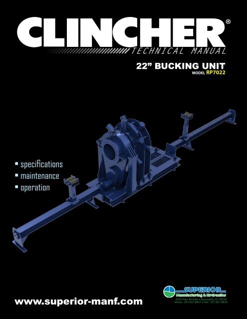
TECHNICAL MANUAL22” BUCKING UNITm o d e l <strong>RP7022</strong>• specifications• maintenance• operationwww.superior-manf.com4225 Hwy 90 East • Broussard, LA 70518Phone: 337.837.8847 • Fax: 337.837.8839
© Copyright 20<strong>10</strong> Superior Manufacturing & Hydraulics (A Division Of <strong>McCoy</strong> Corporation), all rights reserved.This document is the property of Superior Manufacturing & Hydraulics and is supplied as reference informationfor users of our products. This document and the contents within are considered confidential information, not tobe disclosed, copied, transmitted, transcribed in any form, or stored on any type of data storage media without theexpress written consent of Superior Manufacturing & Hydraulics.While continually striving to maintain accuracy, Superior Manufacturing & Hydraulics hereby states that the informationcontained in this technical documentation is subject to change without notice. If you feel this documentdoes not meet your needs, please contact our sales office for the most current available documentation for yourproduct.II
Table of ContentsSection I ------------------------------------------------------General Description -------------------------------------------------- 2Safety Guidelines ---------------------------------------------------- 2Section II -----------------------------------------------------Installation --------------------------------------------------------- 2Start Up ----------------------------------------------------------- 2Section III -----------------------------------------------------Operation ---------------------------------------------------------- 2Make-up ----------------------------------------------------------- 2Break-out ---------------------------------------------------------- 2Section IV ----------------------------------------------------Maintenance -------------------------------------------------------- 3Daily- ------------------------------------------------------------- 3Monthly ----------------------------------------------------------- 3Annually ----------------------------------------------------------- 3Section V - - - - - - - - - - - - - - - - - - - - - - - - - - - - - - - - - - - - - - - - - - - - - - - - - - - - - -Hydraulic Power Unit- ------------------------------------------------- 3Section VI -----------------------------------------------------Specifications ------------------------------------------------------- 3Electric Motor ------------------------------------------------------- 3Hydraulic Oil -------------------------------------------------------- 3Chucking Capacity --------------------------------------------------- 3Torque Capacity ----------------------------------------------------- 3Section VII ----------------------------------------------------Bucking Unit Hydraulic Schematic ---------------------------------------- 4Control Console Hydraulic Schematic ------------------------------------- 5Control Console Electric Schematic -------------------------------------- 6Electric Proportional Schematic ----------------------------------------- 7Power Unit Hydraulic Schematic ----------------------------------------- 8Assembly Drawings -------------------------------------------------- 111
SECTION IGENERAL DESCRIPTION:Your CLINCHER® Bucking Unit is a rugged, self-contained, continuouslyrotating unit designed to accurately make-up or break-out thethreaded connections on tubular components such as oil and gaswell drilling tools, casing, tubing, and similar equipment. The unit willaccurately make-up and break-out thread connections without damageto the thread.Recommended Safety GuidelinesThe safety guidelines that follow are recommended by SuperiorManufacturing & Hydraulics, and are in no way intended to supersedethe specific health and safety regulations and guidelines of ourclient’s workplace. Workplace rules and regulations are the responsibilityof the client.A. Work ApparelTo ensure employee safety, it is recommended that the followingPPE (Personal Protective Equipment) be worn when using and workingaround hydraulic equipment:1. Eye Protection (safety glasses)To avoid risk of eye damage due to:• fracture/failure of die inserts under load• fracture/failure of tool under load• failure of hydraulic hose or component under pressure2. Ear Protection (ear plugs)To prevent hearing damage due to:• electric motor and hydraulic systems noise• sudden and loud noises that may occur during the workprocess3. Head Protection (hard hat)To reduce danger due to:• overhead cranes and hooks• fracture/failure of die inserts under load• fracture/failure of tool under load4. Hand Protection (leather gloves)To avoid danger due to:• metal slivers on the tool or dies produced during thework process• chemicals used during the work process• failure of hydraulic hose or components under pressure5. Foot Protection (steel-toed boots)To prevent injury due to:• falling or rolling work piecesSECTION IIINSTALLATION:1. Inspect unit carefully for shipping damage or missing parts.2. Position unit on a fairly flat and level floor leaving sufficientclearance on both ends to allow the insertion and removalof the longest tools expected to be serviced.3. Anchor the unit in place.4. Clean hydraulic hoses and quick disconnects.5. Attach all hoses that connect the control console to theBucking Unit.6. Fill hydraulic reservoir with recommended hydraulic fluidfiltered using 3 micron filter system. Filler cap/breatheris accessible on left side of unit. Level indicator may beviewed through a window in front.7. Verify suction valve is open if present.8. Fill pump case with filtered hydraulic oil before connectingpower.9. CAUTION: Check that main power supply matches nameplate rating on motor in control console. Use of an incompatiblepower source will result in equipment damage andwill void warranty.START UP:<strong>10</strong>. Connect power supply.11. Check motor rotation by jogging start/stop switch quickly.Reference the rotation plaque attached to the power unit.If rotation is incorrect, switch any two-phase wires at motorstarter.1. Ensure both pressure relief valves are fully rotated counterclockwiseto reduce pressure to minimum.2. Start motor and check for oil leaks in console. Hold backBackup Clamp Cylinder control lever in Open/Retract positionand adjust Clamp Pressure Control until system pressurereads 1,000 psi. Cycle all valves fully several times tocompletely purge all air from the system.3. Check Bucking Unit and Hydraulic Power Unit for leaks.4. Check reservoir for proper fluid levels. Add filtered hydraulicfluid if level is below sight glass when all cylinders are extended.Fill until fluid level reaches midpoint in sight glass.If fluid level is below sight glass level, unit will not operate.SECTION IIIOPERATIONThe E-Stop is located on the control console, and must be pulled outfor the unit to operate. Locate the start button on the motor starter.Push to start main drive motor.1. Start the motor.2. Move Tong Make Up / Break Out lever in either directionuntil the power tong completes a rotation.3. Hold Tailstock Clamp / Unclamp lever in the Unclampposition and adjust Clamp Pressure Control until systempressure reads 1,000 psi. Cycle all levers fully several timesto completely purge all air from the system.4. Position work-piece near center of Headstock, shift theTailstock Clamp / Unclamp lever to the Clamp position.Tailstock Clamp / Unclamp control lever must be left in the‘Clamp’ position while work-piece is in machine.5. Position Tailstock as close as possible to tong, allowingrequired space for thread travel. CAUTION: If adequatespace is not left to accommodate thread travel, the backupwill contact the tong, potentially damaging the equipmentor tubular connection. Such damage is not covered by thewarranty.6. Shift Headstock Clamp / Unclamp lever into Clamp position.7. Using Tong Make Up / Break Out control lever, apply makeupor break-out torque, then rotate headstock.MAKE-UPWhen making up connections, set relief valve to proper settingbefore rotating headstock.BREAK-OUTSet relief valve to proper setting before rotating headstock.2
SECTION IVMAINTENANCEDAILY:1. With all clamp cylinders fully extended, check hydraulicreservoir oil level on sight glass on front of console. Fill withfiltered hydraulic fluid if needed until level reaches midpointon sight glass.2. Inspect die inserts. Clear any debris from around clampcylinders.WEEKLY:1. Remove dies and inspect jaw retainer bolt torque. Torqueshould be set to 180 ft-lbs.MONTHLY:1. Grease fittings.65”70”ANNUALLY (or following any system repair):1. Drain and clean hydraulic reservoir. Analyze contamination/ quality status of hydraulic oil (with the use of an analysiskit or by other third party means). Filter / replace oil asrequired.2.3.Remove and clean suction strainer.Refill reservoir with new filtered hydraulic oil.99”SECTION VHYDRAULIC POWER UNIT153”The hydraulic power unit incorporates a number of pressure controland relief valves. These valves are correctly adjusted and set prior toshipment from our factory.CAUTION: Adjusting internal relief valves or pump compensator settingswill void warranty.52”SECTION VISPECIFICATIONS85” 42”Console / Power Unit:Electric Motor: 50 Horsepower, 440 Volt, 3 phase, 60 HertzHydraulic Oil: AW-68Hyd. Oil Capacity: 90 gal.Overall Length: 42”Overall Width: 85”Overall Height: 522”Weight (approx.): 3,000 lbs.Bucking Unit:Max. Torque: <strong>10</strong>5,000 ft-lbsHandle Length: 36”Overall Length: 153”Overall Width: 70”Overall Height: 99”Weight (approx.): 18,000 lbs.CHUCKING CAPACITIES7” to 21 1/2” DiameterTORQUE CAPACITYMake-up <strong>10</strong>5,000 foot pounds / Break-out <strong>10</strong>5,000 foot pounds3
Bucking UnitHydraulic SchematicCLINCHER® RP70004
Control ConsoleHydraulic Schematic5
Control ConsoleElectrical Schematic6
Electric Proportional Schematic7
Power UnitHydraulic Schematic8
Page intentionally left blank9
<strong>10</strong>Page intentionally left blank
<strong>RP7022</strong>Continuously Rotating Bucking UnitAssembly DrawingsA C DBDEDABCDETail Stock Assembly -------------------------------------------------- 12Tong Assembly ----------------------------------------------------- 14Head Stock Assembly ----------------------------------------------- 14Tong Body Assembly ----------------------------------------------- 16Clamp Cylinder Assembly ---------------------------------------------- 18Skid Assembly with Power Traverse, Extension Beams, and Support Rollers -------- 20Control Console / Power Unit Assembly - - - - - - - - - - - - - - - - - - - - - - - - - - - - - - - - - - - - - 23Notice: All drawings contained in this manual are the property of Superior Manufacturing & Hydraulics and are considered confidential.This information may not be used, disclosed, copied, or reproduced in any form, without the express written consent ofSuperior Manufacturing & Hydraulics.For third party component documentation used within this unit, please contact Superior Manufacturing & Hydraulics.11
300-7000-22Tail Stock Assembly789<strong>10</strong> 1127 28 29 30 31 32 331234512 131461516 17181920212224 25 262312
300-7000-22Tail Stock AssemblyItem # Qty. Part NumberPart Name1 1 351-7000-2 TAIL STOCK VISE ASSEMBLY2 6 400-7000-2 CLAMP CYLINDER ASSEMBLY3 2 301A-7000-22 TAIL STOCK INNER MOUNT PLATE4 24 1773 SHCS FLAT 1/2”-13 x 1”5 2 3<strong>03</strong>-7000-22 TAIL STOCK INNER BEARING6 20 1774 SHCS FLAT 1/2”-13 x 1-1/2”7 1 3<strong>10</strong>-7000-22 TAIL STOCK PLATE8 2 3<strong>03</strong>B-6500 LOAD CELL DEAD PIN9 4 309D-7000 LOAD CELL LOCK PIN<strong>10</strong> 2 309-7000 LOAD CELL BRACKET11 2 309B-7000 LOAD CELL BRACKET #212 1 3<strong>10</strong>A-7000-22 TAIL STOCK PLATE13 18 1223 1 1/2” LOCK WASHER14 18 1187 1 1/2”-6 HEX NUT15 1 SG350-CPO BEARING16 2 302-700-22 OUTER BEARING CAP FOR 22” TAIL STOCK17 32 11<strong>03</strong> 1/2” LOCK WASHER18 32 1112-A 1/2”-13 x 2” HHCS19 2 1123-3000 TRANSFER BALL ROLLER20 1 901C-7000 UPPER SUPPORT TUBE21 2 309D-7000 LOAD CELL LOCK PIN22 1 1122-7000 LOWER SUPPORT WELDMENT23 1 902B-3000-1 1” x 7-3/4” HITCH PIN24 2 1115-3000 MOUNT ANGLE25 12 1151 5/8” LOCK WASHER26 6 1157 5/8”-11 x 1-1/2” HHCS27 1 3<strong>10</strong>-7000-1 CARRIAGE ASSEMBLY28 4 3<strong>10</strong>E-7000 1-3/4” CAM FOLLOWER29 18 1223 1-1/2” LOCK WASHER30 18 1187 1-1/2”-6 HEX NUT31 14 1218 1” LOCK WASHER32 14 1264 1”-13 x 2-1/2” HHCS33 4 3<strong>10</strong>F-7000 3-1/2” CAM FOLLOWER13
200-7000-22ATong Assembly127B17A5 6 18ASSEMBLY NO. 200-7000-22A<strong>10</strong>B8 9 121334111491591614
200-7000-22ATong AssemblyItem # Qty. Part NumberPart Name1 12 1291 1”-8 x 4” HHCS2 1 N/A TONG SHROUD3 12 1218 1” LOCK WASHER4 12 12<strong>10</strong> 1”-8 NUT5 6 1127 1/2”-13 x 4-3/4” SHCS6 1 2<strong>03</strong>-7000-22 HEAD STOCK INNER MANIFOLD7 6 400-7000-2 CLAMP CYLINDER ASSEMBLY8 24 <strong>10</strong>46 3/8”-16 x 3/4” HHCS9 32 <strong>10</strong>27 3/8” LOCK WASHER<strong>10</strong> 24 222B-3500 CYLINDER PIN RETAINER11 1 12-20_f5ox-s N/A12 4 <strong>10</strong>47 3/8”-16 x 1” HHCS13 1 RP14S3500-<strong>10</strong>01-S1 FLOW DIVIDER14 4 <strong>10</strong>48 3/8”-16 x 1-1/4” HHCS15 1 253-7000 FLOW DIVIDER MOUNT16 4 <strong>10</strong>24 3/8”-16 HEX NUT17 4 1609 3/8” NPT PLUG18 6 1325 3/4”-<strong>10</strong> x 2 3/4” SHCS15
2 3 55 4200-7000-22Tong Body Assembly43441727AA404142B1245646161211<strong>10</strong>8 95 6 747131819 201413152221B313233343536<strong>10</strong>113<strong>03</strong>724383739<strong>10</strong> 1126<strong>10</strong>112923242516
200-7000-22Tong Body AssemblyItem# Qty. Part NumberPart Name1 1 204-7000-22 HYDRAULIC SWIVEL2 1 235-7000 HYDRAULIC MOTOR3 <strong>10</strong> <strong>10</strong>85-A 7/16”-20 HHCS4 1 211A-7000 MOTOR MOUNT TOP PLATE5 1 1772 1/2”-13 x 1” FLAT SCHS6 2 507D-7000 DRIVE GEAR RETAINER7 1 209B-7000 HIGH PINION GEAR8 6 1132-B 1/2”-13 x 1 3/4” SCHCS9 1 208-7000 HEAD STOCK TOP BEARING CAP<strong>10</strong> 86 173 1/2”-13 x 2 1/4” HHCS11 86 11<strong>03</strong> 1/2” LOCK WASHER12 1 200B-7000 TOP TONG PLATE13 2 209-7000-1 PINION SPROCKET BEARING14 1 209-7000 PINION SPROCKET15 1 247-7000 20’ COTTERED CHAIN (ANSI# <strong>10</strong>0-3)16 2 2<strong>10</strong>-7000 HEAD STOCK BEARING CAP17 3 CB2221 SWIVEL SEAL18 1 212-7000 BULL GEAR SPROCKET19 2 2<strong>10</strong>C-7000 GARLOCK OIL SEAL20 2 2<strong>10</strong>A-7000 30” FOUR CONTACT THINSECTION BEARING21 1 202-7000-22 22” FINAL DRIVE22 6 249 1/2”-13 x 2” SHCS23 32 <strong>10</strong>49 3/8”-16 x 1 1/2” HHCS24 34 <strong>10</strong>27 3/8” LOCK WASHERItem# Qty. Part NumberPart Name25 2 2<strong>10</strong>-7000 HEAD STOCK BEARING CAP26 2 1771 1/4” NPT GREASE ZERT27 13 253 1/2”-13 x 2 1/4” HHCS29 1 206A-7000 HEAD STOCK BEARING CAP30 1 200C-7000 BOTTOM TONG PLATE31 1 1167 3/4”-<strong>10</strong> NYLOCK HEX NUT32 1 CB2324 SPRING WASHER33 1 CB2326 COMRPESSION SPRING34 1 CB2325-S1 THREADED LIFTING ROD35 1 1176-A 3/4” NUT36 2 2001-7000-22 SWIVEL SUPPORT WELDMENT37 4 <strong>10</strong>40-A 3/8”-16 x 3/4” SHCS38 1 CB2323 SPRING COVER39 1 CB2322 SPRING TUBE40 4 1173 3/4”-<strong>10</strong> x 1 3/4” HHCS41 4 1171 3/4” LOCK WASHER42 2 2507-7000 SWIVEL RETAINER F/ <strong>RP7022</strong>43 6 251 1/2”-13 x 3” SHCS44 2 2500-7000 SWIVEL KEEPER WELDMENT45 1 209C-7000 MOTOR DRIVE GEAR46 1 1132-C 1/2”-20 x 1” FLAT SHCS47 1 200D-7000-22 TONG CASE WELDMENT17
400-7000-2Clamp Cylinder Assembly8146 9O-RING PART OFPISTON ROD ASSY.A4111269127A5BCDSECTION A-ADETAIL DSCALE 1 : 4<strong>10</strong>15DETAIL BSCALE 1 : 4DETAIL CSCALE 1 : 418
400-7000-2Clamp Cylinder AssemblyItem # Qty. Part NumberPart Name1 2 <strong>10</strong>23-N 5/16" X 5/8" DOWEL PIN2 2 1112 1/2"-13 x 1 1/2" HHCS3 1 1570 3/8" MNPT X 3/8" MJIC STRAIGHT4 2 1577-A 90 3/8" MNPT X 3/8" MJIC5 2 260 5/8-11 x 2 SHCS6 1 400-7000 CYLINDER BLOCK HOUSING WELDMENT F/ 22"7 1 401-3000-1 END PLATE WELDMENDT8 1 402-3000 STANDARD JAW HOLDER9 1 404-7000 SEAL PLATE WELDMENT<strong>10</strong> 1 405-3000 SPLIT RING11 2 408-3000 3/8" WASHER12 2 91253B SHCS Flat 1/2"-13 x 7/8"13 1 400C-3000 SEALS KIT14 1 4<strong>03</strong>-7000-2 PISTON/ROD ASSEMBLY15 1 DTI1602 DOVETAIL STRIP DIE (1 1/4" x 1/2" x 5")19
500-7000-2212’ Skid Assembly(shown with Extension Beams & Hydraulic Support Rollers)9<strong>10</strong>B167811 12 13 14 15565ASSEMBLY NO. 900-70001234202122232425262723252826 24B171819A111229FRONTA2623333<strong>03</strong>124252732 26FRONT20
500-7000-2212’ Skid Assembly(shown with Extension Beams & Hydraulic Support Rollers)Item# Qty. Part NumberPart Name1 4 901A-3000-1 RED ROLLER2 8 904-3000 SUPPORT STAND BEARING3 16 11<strong>03</strong> 1/2” LOCK WASHER4 16 1111 1 1/2” SUPPORT STAND5 2 901-7000 TOP SUPPORT WELDMENT6 2 901D-7000 2” BORE CHIEF CYLINDER7 2 902-7000 BOTTOM SUPPORT WELDMENT8 2 902B-3000-1 1” x 7 3/4” HITCH PIN9 12 902D-3000-1 1 3/4” ROLLER<strong>10</strong> 12 275-A 1”-14 THIN NYLOCK NUT11 16 1174 3/4”-<strong>10</strong> x 2 1/4” HHCS12 16 1171 3/4” LOCK WASHER13 1 1200-7000-1 <strong>10</strong>’ EXTENSION BEAM ASSY.14 8 1264 1”-8 x 2 1/2” HHCS15 8 1218 1” LOCK WASHER16 1 556-7000-22 20’ TRAVEL CHAIN17 2 6-<strong>10</strong>_f5ox-s N/A18 4 246 SHCS 1/2”-13 x 1”19 1 511-6500 TRAVEL MOTOR20 1 515B-3000 MODIFIED 1” L-COUPLING21 1 515C-3000 COUPLING SPIDER22 1 515A-3000 1 1/2” BORE - COUPLING23 2 5<strong>10</strong>C-3000 TRAVERSE SPROCKET KEYa24 8 11<strong>10</strong> 1/2”-13 x 1” HHCS25 8 11<strong>03</strong> 1/2” LOCK WASHER26 4 508-3000 1 1/2” BEARING27 2 509-3000 TRAVEL SPROCKET28 1 502B-6500 TRAVEL SPROCKET SHAFT29 4 540-3000 BUMPER STOP ASSEMBLY30 2 <strong>10</strong>48 3/8”-16 x 1 1/4” HHCS31 2 <strong>10</strong>27 3/8” LOCK WASHER32 1 5<strong>10</strong>B-3000 TRAVEL SPROCKET SHORT SHAFT33 1 1250-7000-1 15’ BEAM EXTENSION ASSEMBLY21
22Page intentionally left blank
<strong>10</strong>0-7000-2Control Console / Power Unit Assembly55433615987<strong>10</strong>1Item # Qty. Part NumberPart Name1 1 <strong>10</strong>0-6500 CONSOLE WELDMENT2 2 12 WFTX-S 3/4" BULKHEAD CONNECTOR MNPT3 2 130-6500 PRESSURE CONTROL VALVE4 1 132-6500 0-<strong>10</strong>00 PSI GAUGE5 3 133-6500 0-3000 PSI GAUGE6 1 150-7000-22 TOP COVER PLATE7 1 152-6500 BULKHEAD COVER8 1 CLEBU12<strong>10</strong>-01 TORQUE COMPUTER MOUNT (EXTENDED)9 1 Stop Button<strong>10</strong> 1 Power Unit23