Modeling of FACTS Devices Based on SPWM VSCs - CIEP
Modeling of FACTS Devices Based on SPWM VSCs - CIEP
Modeling of FACTS Devices Based on SPWM VSCs - CIEP
- No tags were found...

You also want an ePaper? Increase the reach of your titles
YUMPU automatically turns print PDFs into web optimized ePapers that Google loves.
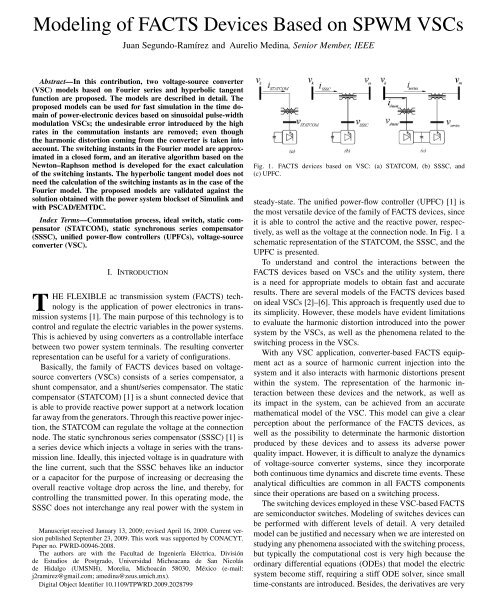
Fig. 3. Single-phase equivalent circuit.disc<strong>on</strong>tinuities produced during the commutati<strong>on</strong> process areavoided if a smoother pulse train obtained with the Fourierseries replaces in (3).The switching instants are obtained with the soluti<strong>on</strong> <str<strong>on</strong>g>of</str<strong>on</strong>g>the n<strong>on</strong>linear algebraic equati<strong>on</strong>s set describing the sawtoothwaveform and . In principle, the computati<strong>on</strong> <str<strong>on</strong>g>of</str<strong>on</strong>g> the switchinginstants requires the applicati<strong>on</strong> <str<strong>on</strong>g>of</str<strong>on</strong>g> an iterative process for thesoluti<strong>on</strong> <str<strong>on</strong>g>of</str<strong>on</strong>g> the n<strong>on</strong>linear algebraic equati<strong>on</strong>s. However, canbe approximated through a first order Taylor series, to allowthe original n<strong>on</strong>linear algebraic system to be transformed into alinear algebraic system. Let’s be the approximated switchinginstants. The equati<strong>on</strong>s defining the straight lines with positiveslope for the triangular signal <str<strong>on</strong>g>of</str<strong>on</strong>g> Fig. 4(a) are given byThe equati<strong>on</strong>s defining the straight lines with negative slopefor the triangular signal are given by(4)(5)Fig. 4. Transforming a desired c<strong>on</strong>tinuous signal v(a) <strong>SPWM</strong> process. (b) Switching functi<strong>on</strong> (S).into a <strong>SPWM</strong> signal.where is the fundamental period <str<strong>on</strong>g>of</str<strong>on</strong>g> and is the positiveslope, calculated as(6)achieve this result, a sawtooth wave (tri) is drawn. Now, c<strong>on</strong>ducti<strong>on</strong>takes place whenever lies above the triangular waveform(tri), and c<strong>on</strong>ducti<strong>on</strong> ceases whenever it lies below. The resultingpulse train c<strong>on</strong>tains the signal . The <strong>SPWM</strong> processis illustrated by Fig. 4(a). The corresp<strong>on</strong>ding switching functi<strong>on</strong>is shown in Fig. 4(b). This switching functi<strong>on</strong> corresp<strong>on</strong>ds<strong>on</strong>ly to <strong>on</strong>e phase; however, it can be extended to the other twophases.In practice, is much shorter than that shown in Fig. 4(a).C<strong>on</strong>sequently, the change in during <strong>on</strong>e carrier period isc<strong>on</strong>siderably less than the indicated in Fig. 4(a). In other words,a higher carrier frequency directly improves the reproducti<strong>on</strong><str<strong>on</strong>g>of</str<strong>on</strong>g> the original signal ; the carrier frequency is defined as.The frequency-modulati<strong>on</strong> radio is defined as ,where is the frequency <str<strong>on</strong>g>of</str<strong>on</strong>g> . Higher implies a highswitching frequency. As we have menti<strong>on</strong>ed before, there areseveral simulati<strong>on</strong> problems related to the switching process.In additi<strong>on</strong>, the numerical error increases with the increase inthe switching frequency.In the next secti<strong>on</strong>, the two proposed models for the fast andefficient simulati<strong>on</strong> <str<strong>on</strong>g>of</str<strong>on</strong>g> VSC power c<strong>on</strong>verters are detailed.III. SINUSOIDAL PULSE-WIDTH MODULATIONCONVERTER REPRESENTATIONA. Fourier ModelIt can be observed that the switching functi<strong>on</strong> shown inFig. 4(b) c<strong>on</strong>tains disc<strong>on</strong>tinuities at each switching instant. TheThe c<strong>on</strong>trol signalis given byits first-order Taylor approximati<strong>on</strong> aroundFor instance, the switching instant for iscomputed throughwith, thenis(7)(8)(9)(10)For , with , we obtainIn general, for(11)(12)
Fig. 5. Time-domain comparis<strong>on</strong> between the disc<strong>on</strong>tinuous switching functi<strong>on</strong>S and the Fourier approach for different harm<strong>on</strong>ic orders.where(13)Equati<strong>on</strong> (12) is the general expressi<strong>on</strong> for the approximatedcomputati<strong>on</strong> <str<strong>on</strong>g>of</str<strong>on</strong>g> the switching instants. Once has been calculated,the pulse train is automatically obtained. The proposedmodel can be resumed by using an approximati<strong>on</strong> <str<strong>on</strong>g>of</str<strong>on</strong>g> in terms<str<strong>on</strong>g>of</str<strong>on</strong>g> the Fourier series, e.g., , beingwhereis the highest harm<strong>on</strong>ic order, and(14)(15)(16)Fig. 6. Spectrum comparis<strong>on</strong> between the disc<strong>on</strong>tinuous switching functi<strong>on</strong> Sand the Fourier approach for different harm<strong>on</strong>ic orders.harm<strong>on</strong>ic orders is presented. In Fig. 5(a) a time-domain comparis<strong>on</strong>between and for a maximum harm<strong>on</strong>ic order <str<strong>on</strong>g>of</str<strong>on</strong>g> 19(1140 Hz) is shown, in Fig. 5(b) for a maximum harm<strong>on</strong>ic order<str<strong>on</strong>g>of</str<strong>on</strong>g> 113 (6780 Hz), and in Fig. 5(c) for a maximum harm<strong>on</strong>icorder <str<strong>on</strong>g>of</str<strong>on</strong>g> 300 (18 kHz), respectively. Fig. 6 shows the harm<strong>on</strong>icdomain comparis<strong>on</strong>; in Fig. 6(a) a harm<strong>on</strong>ic domain comparis<strong>on</strong>between and for a maximum harm<strong>on</strong>ic order <str<strong>on</strong>g>of</str<strong>on</strong>g> 19(1140 Hz) is shown, in Fig. 6(b) for a maximum harm<strong>on</strong>ic order<str<strong>on</strong>g>of</str<strong>on</strong>g> 113 (6780 Hz), and in Fig. 6(c) for a maximum harm<strong>on</strong>icorder <str<strong>on</strong>g>of</str<strong>on</strong>g> 300 (18 kHz), respectively. The obtained resp<strong>on</strong>ses arein close agreement.It can be noticed from Fig. 6 that for a Fourier series approximati<strong>on</strong>with a maximum harm<strong>on</strong>ic order <str<strong>on</strong>g>of</str<strong>on</strong>g> , the switchingfuncti<strong>on</strong> c<strong>on</strong>tains up to the harm<strong>on</strong>ic <str<strong>on</strong>g>of</str<strong>on</strong>g> , where all theharm<strong>on</strong>ics are included. If higher precisi<strong>on</strong> is required, an iterativeprocess can be implemented with (12) to increase theprecisi<strong>on</strong>, so that(17)For the balanced case, is calculated for <strong>on</strong>e phase, andfor the other phases it is obtained with the appropriate phaseangle if is multiple <str<strong>on</strong>g>of</str<strong>on</strong>g> three. In additi<strong>on</strong>, if is odd theswitching functi<strong>on</strong> have half-wave symmetry, c<strong>on</strong>sequently, alleven-numbered harm<strong>on</strong>ics vanish. In additi<strong>on</strong>(18)Using half-wave symmetry property, we <strong>on</strong>ly need to computethe half <str<strong>on</strong>g>of</str<strong>on</strong>g> the switching times with (18).It is clear that with this Fourier series approximati<strong>on</strong>, the harm<strong>on</strong>icnumber for the analysis can be selected. The harm<strong>on</strong>icnumber introduced in the analysis increases the computati<strong>on</strong>aleffort for each integrati<strong>on</strong> step; however, this aspect is compensatedwith the use <str<strong>on</strong>g>of</str<strong>on</strong>g> larger integrati<strong>on</strong> steps, since the disc<strong>on</strong>tinuitiesno l<strong>on</strong>ger exist.In Fig. 5, a time-domain comparis<strong>on</strong> between the disc<strong>on</strong>tinuousswitching functi<strong>on</strong> and the Fourier approach for different(19)for , (19) corresp<strong>on</strong>ds to (12). It can be noticed that (19) isthe iterative Newt<strong>on</strong> method. Expressi<strong>on</strong> (19) can be also representedas(20)The harm<strong>on</strong>ic spectrum <str<strong>on</strong>g>of</str<strong>on</strong>g> (14) is finite; for this reas<strong>on</strong>,there are not aliasing problems if the selected integrati<strong>on</strong> stepis chosen according to the Nyquist criteri<strong>on</strong>. For example, forequal to 51 with a fundamental frequency <str<strong>on</strong>g>of</str<strong>on</strong>g> 60 Hz, theintegrati<strong>on</strong> step must be at leasts. A smaller integrati<strong>on</strong>step would be necessary if numerical stability problemsare detected, since this integrati<strong>on</strong> step is in general large.B. Smooth Switching Functi<strong>on</strong>A numerical error is introduced during the numerical integrati<strong>on</strong><str<strong>on</strong>g>of</str<strong>on</strong>g> electric systems including power-electr<strong>on</strong>ic switchescoming from the disc<strong>on</strong>tinuities <str<strong>on</strong>g>of</str<strong>on</strong>g> the ideal switch model.
Fig. 21.Transient soluti<strong>on</strong> comparis<strong>on</strong> for the UPFC.Fig. 19. Steady-state soluti<strong>on</strong> comparis<strong>on</strong> for the SSSC.Fig. 22. Steady-state soluti<strong>on</strong> comparis<strong>on</strong> for the UPFC.Fig. 20. Harm<strong>on</strong>ic c<strong>on</strong>tent comparis<strong>on</strong>s. (a) Harm<strong>on</strong>ic c<strong>on</strong>tent in the dcvoltage. (b) Magnitude <str<strong>on</strong>g>of</str<strong>on</strong>g> selected harm<strong>on</strong>ics in phase A <str<strong>on</strong>g>of</str<strong>on</strong>g> the terminalvoltage. (c) Magnitude <str<strong>on</strong>g>of</str<strong>on</strong>g> selected harm<strong>on</strong>ics in the phase A <str<strong>on</strong>g>of</str<strong>on</strong>g> the seriescurrent.Simulink PSCAD/EMTDC, and the two proposed models. Anintegrati<strong>on</strong> step <str<strong>on</strong>g>of</str<strong>on</strong>g> 0.1 s has been used in Simulink, 100 sfor the Fourier approach method, 30 s for the hyperbolictangent model, and 0.1 s in PSCAD/EMTDC. Observe thatthe proposed models closely agree with the soluti<strong>on</strong> obtainedwith Simulink and PSCAD/EMTDC.A comparis<strong>on</strong> between the periodic steady-state soluti<strong>on</strong>sis shown in Fig. 19; the capacitor voltage is shown inFig. 19(a), the terminal voltage at node 1 in Fig. 19(b),and the phase A <str<strong>on</strong>g>of</str<strong>on</strong>g> the series current in Fig. 19(c), respectively.Observe that all soluti<strong>on</strong>s are again in very closeagreement.Fig. 20(a) shows the harm<strong>on</strong>ic c<strong>on</strong>tent for , in Fig. 20(b)for , and in Fig. 20(c) for . It can be seen that the proposedmodels are in very good agreement with the soluti<strong>on</strong> obtainedwith Simulink and PSCAD/EMTDC.3) Unified Power Flow C<strong>on</strong>troller (UPFC): The UPFC includesthe shunt c<strong>on</strong>trol described in [15], and the series c<strong>on</strong>trolproposed in [16]. The initial c<strong>on</strong>diti<strong>on</strong> is zero, except for thedc capacitor voltage, which is 2 p.u. The series c<strong>on</strong>troller regulatesthe real ( p.u.) and reactive ( p.u.)power flows by adjusting the injected series voltage. The shuntc<strong>on</strong>verter regulates the dc-side capacitor voltage ( p.u.)and the sending end voltage ( p.u.). The modulati<strong>on</strong>index is . The maximum harm<strong>on</strong>ic order in the Fourierapproach is 69 (4140 Hz).Fig. 21 shows the transient soluti<strong>on</strong> comparis<strong>on</strong> for the capacitorvoltage <str<strong>on</strong>g>of</str<strong>on</strong>g> the UPFC operating in open-loop c<strong>on</strong>trol.For this operating mode, the initial c<strong>on</strong>diti<strong>on</strong> has been assumedzero. This soluti<strong>on</strong> has been computed using Simulink, PSCAD/EMTDC and the two proposed models. An integrati<strong>on</strong> step <str<strong>on</strong>g>of</str<strong>on</strong>g>0.1 s has been used in Simulink and PSCAD/EMTDC, 80 sfor the Fourier approach method, and 30 s for the hyperbolictangent model.A comparis<strong>on</strong> between the periodic steady-state soluti<strong>on</strong> obtainedwith Simulink, the Fourier model, the hyperbolic tangentmodel, and PSCAD/EMTDC is shown in Fig. 22. Fig. 22(a)shows the capacitor voltage , Fig. 22(b) shows the voltage<str<strong>on</strong>g>of</str<strong>on</strong>g> phase A in bus 1, and Fig. 22(c) shows the series current<str<strong>on</strong>g>of</str<strong>on</strong>g> phase A . The slight difference between the soluti<strong>on</strong>obtained with PSCAD/EMTDC and the other soluti<strong>on</strong>s is becausethe UPFC implemented in PSCAD/EMTDC is operatingin open-loop c<strong>on</strong>trol, meanwhile, the other soluti<strong>on</strong>s are operatingin closed-loop c<strong>on</strong>trol; however, all the soluti<strong>on</strong>s are ingood agreement.
ACKNOWLEDGMENTThe authors thank the Universidad Michoacana de SanNicolás de Hidalgo (UMSNH) through the División de Estudiosde Posgrado, Facultad de Ingeniería Eléctrica, for thefacilities that were granted to carry out this investigati<strong>on</strong>. Theauthors would also like to thank Pr<str<strong>on</strong>g>of</str<strong>on</strong>g>. Dr. E. Barcenas fromthe Instituto Tecnológico Superior de Irapuato (ITESI) for hisvaluable suggesti<strong>on</strong>s and comments.REFERENCESFig. 23. Harm<strong>on</strong>ic c<strong>on</strong>tent comparis<strong>on</strong>s. (a) Harm<strong>on</strong>ic c<strong>on</strong>tent in the dcvoltage. (b) Magnitude <str<strong>on</strong>g>of</str<strong>on</strong>g> selected harm<strong>on</strong>ics in phase A <str<strong>on</strong>g>of</str<strong>on</strong>g> the terminalvoltage. (c) Magnitude <str<strong>on</strong>g>of</str<strong>on</strong>g> selected harm<strong>on</strong>ics in the phase A <str<strong>on</strong>g>of</str<strong>on</strong>g> the seriescurrent.A validati<strong>on</strong> <str<strong>on</strong>g>of</str<strong>on</strong>g> the proposed models is further illustrated inFig. 23, which shows the harm<strong>on</strong>ic spectrum for the capacitorvoltage in Fig. 23(a), the voltage <str<strong>on</strong>g>of</str<strong>on</strong>g> phase A at node 1 inFig. 23(b), and the phase A <str<strong>on</strong>g>of</str<strong>on</strong>g> the series current in Fig. 23(c),respectively; all the soluti<strong>on</strong>s are in excellent agreement.V. CONCLUSIONTwo efficient VSC models based <strong>on</strong> Fourier series approachand hyperbolic tangent have been proposed for the six-pulsec<strong>on</strong>verter. The proposed models have been used for the computati<strong>on</strong><str<strong>on</strong>g>of</str<strong>on</strong>g> the soluti<strong>on</strong> <str<strong>on</strong>g>of</str<strong>on</strong>g> <str<strong>on</strong>g>FACTS</str<strong>on</strong>g> devices c<strong>on</strong>nected to a powernetwork.It has been shown that the proposed models can be used tocompute both the transient and the periodic steady-state soluti<strong>on</strong><str<strong>on</strong>g>of</str<strong>on</strong>g> a power network c<strong>on</strong>taining VSC-based <str<strong>on</strong>g>FACTS</str<strong>on</strong>g>.The resp<strong>on</strong>se given by the proposed methods has been successfullyvalidated against the soluti<strong>on</strong> obtained with the widelyaccepted digital simulators Simulink and PSCAD/EMTDC, respectively,in all the cases the obtained results were in excellentagreement. In additi<strong>on</strong>, it has been shown through simulati<strong>on</strong>sthat the proposed models allow significant larger integrati<strong>on</strong>steps, as compared with the ideal switch model approach,e.g., for the c<strong>on</strong>ducted studies, more than 800 times the integrati<strong>on</strong>step needed by Simulink and PSCAD/EMTDC when theFourier approach was used, and at least 300 times when the hyperbolictangent method was applied.The proposed <strong>VSCs</strong> models have been <strong>on</strong>ly implemented in anetwork including <str<strong>on</strong>g>FACTS</str<strong>on</strong>g> devices; however, these models canbe used in any power-electr<strong>on</strong>ic device based <strong>on</strong> <strong>SPWM</strong> sixpulse c<strong>on</strong>verters, or even for multilevel c<strong>on</strong>verters based <strong>on</strong> arrangement<str<strong>on</strong>g>of</str<strong>on</strong>g> six-pulse c<strong>on</strong>verters.[1] N. G. Hingorani and L. Gyugyi, Understanding <str<strong>on</strong>g>FACTS</str<strong>on</strong>g>. Piscataway,NJ: IEEE Press, 2000.[2] E. Uzunovic, C. A. Cañizares, and J. Reeve, “Fundamental frequencymodel <str<strong>on</strong>g>of</str<strong>on</strong>g> unified power flow c<strong>on</strong>troller,” in Proc. North AmericanPower Symp., Cleveland, OH, Oct. 1998, pp. 294–299.[3] A. Nahavi-Niaki and M. R. Iravani, “Steady-state and dynamic models<str<strong>on</strong>g>of</str<strong>on</strong>g> unified power flow c<strong>on</strong>troller for power system studies,” IEEE Trans.Power Syst., vol. 11, no. 4, pp. 1937–1943, Nov. 1996.[4] M. Tavakoli Bina and D. C. Hamill, “Average circuit model for anglec<strong>on</strong>trolledSTATCOM,” Proc. Inst. Elect. Eng. Power Appl., vol. 152,no. 3, pp. 653–659, May 2005.[5] E. Uzunovic, C. Cañizares, and J. Reeve, “Fundamental frequencymodel <str<strong>on</strong>g>of</str<strong>on</strong>g> static synchr<strong>on</strong>ous compensator,” in Proc. North AmericanPower Symp., Laramie, WY, Oct. 1997, pp. 49–54.[6] C. A. Cañizares, “Power flow and transient stability models <str<strong>on</strong>g>of</str<strong>on</strong>g> <str<strong>on</strong>g>FACTS</str<strong>on</strong>g>c<strong>on</strong>trollers for voltage and angle stability studies,” in Proc. IEEE PowerEng. Soc. Winter Meeting, Singapore, Jan. 2000.[7] J. Vlach, J. M. Wojciechowski, and A. Opal, “Analysis <str<strong>on</strong>g>of</str<strong>on</strong>g> n<strong>on</strong>linear networkswith inc<strong>on</strong>sistent initial c<strong>on</strong>diti<strong>on</strong>s,” IEEE Trans. Circuits Syst.,vol. 42, no. 4, pp. 195–200, Apr. 1995.[8] EMTDC User’s Guide 2003, HVDC Res. Ctr..[9] I. A. Hiskens and M. A. Pai, “Trajectory sensitivity analysis <str<strong>on</strong>g>of</str<strong>on</strong>g> hybridsystems,” IEEE Trans. Circuits Syst. I, vol. 47, no. 2, pt. I, pp. 204–220,Feb. 2000.[10] P. W. Lehn, “Exact modeling <str<strong>on</strong>g>of</str<strong>on</strong>g> the voltage source c<strong>on</strong>verter,” IEEETrans. Power Del., vol. 17, no. 1, pp. 217–222, Jan. 2002.[11] K. L. Lian and P. W. Lehn, “Steady-state soluti<strong>on</strong> <str<strong>on</strong>g>of</str<strong>on</strong>g> a voltage-sourcec<strong>on</strong>verter with full closed-loop c<strong>on</strong>trol,” IEEE Trans. Circuits Syst., vol.21, no. 4, pp. 2071–2081, Oct. 2006.[12] P. Zuniga-Haro and J. Ramirez, “Multi-pulse switching functi<strong>on</strong>s modeling<str<strong>on</strong>g>of</str<strong>on</strong>g> flexible AC transmissi<strong>on</strong> systems devices,” Elect. Power Comp<strong>on</strong>entsSyst., vol. 37, no. 1, pp. 20–42, Jan. 2009.[13] C. E. Shann<strong>on</strong>, “Communicati<strong>on</strong> in presence <str<strong>on</strong>g>of</str<strong>on</strong>g> noise,” Reprint asClassic Paper in: Proc. IEEE, vol. 86, no. 2, pp. 447–457, Feb. 1998.[14] Power System Blockset User’s Guide 2001, TEQSIM Int. Inc..[15] B. Mahyavanshi and G. Radman, “A study <str<strong>on</strong>g>of</str<strong>on</strong>g> interacti<strong>on</strong> betweendynamic load and STATCOM,” presented at the Southeastern Symp.System Theory, Cookeville, TN, Mar. 5–7, 2006.[16] H. Fujita, Y. Watanabe, and H. Akagi, “Transient analysis <str<strong>on</strong>g>of</str<strong>on</strong>g> a unifiedpower flow c<strong>on</strong>troller and its applicati<strong>on</strong>s to design <str<strong>on</strong>g>of</str<strong>on</strong>g> the DC link capacitor,”IEEE Trans. Power Electr<strong>on</strong>., vol. 16, no. 5, pp. 735–740, Sep.2001.Juan Segundo-Ramírez received the B.S. degree in electromechanical engineeringfrom the Instituto Tecnológico de Lázaro Cárdenas, Lázaro Cárdenas,Mexico, in 2001, the M.Sc. degree from the CINVESTAV Guadalajara,Guadalajara, Mexico, in 2004, and is currently pursuing the Ph.D. degreeat the División de Estudios de Posgrado, Facultad de Ingeniería Eléctrica,Universidad Michoacana de San Nicolás de Hidalgo (UMSNH), Morelia,México.His area <str<strong>on</strong>g>of</str<strong>on</strong>g> research is the dynamic and steady-state analysis <str<strong>on</strong>g>of</str<strong>on</strong>g> powersystems.Aurelio Medina (SM’02) received the Ph.D. degree from the University <str<strong>on</strong>g>of</str<strong>on</strong>g>Canterbury, Christchurch, New Zealand, in 1992.He was a Postdoctoral Fellow at the University <str<strong>on</strong>g>of</str<strong>on</strong>g> Canterbury, New Zealand,for <strong>on</strong>e year and at the University <str<strong>on</strong>g>of</str<strong>on</strong>g> Tor<strong>on</strong>to, Tor<strong>on</strong>to, ON, Canada, for twoyears. He is currently a staff member with the Facultad de Ingeniería Eléctrica,Universidad Michoacana de San Nicolás de Hidalgo (UMSNH), Morelia,México, where he is the Head <str<strong>on</strong>g>of</str<strong>on</strong>g> the Divisi<strong>on</strong> for postgraduate studies. His researchinterests are in the dynamic and steady-state analysis <str<strong>on</strong>g>of</str<strong>on</strong>g> power systems.