PRE INVESTIGATION CONCEPT INFORMATION - Organic Power
PRE INVESTIGATION CONCEPT INFORMATION - Organic Power
PRE INVESTIGATION CONCEPT INFORMATION - Organic Power
- No tags were found...

Create successful ePaper yourself
Turn your PDF publications into a flip-book with our unique Google optimized e-Paper software.
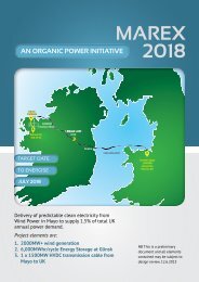
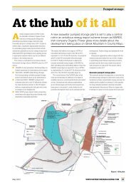
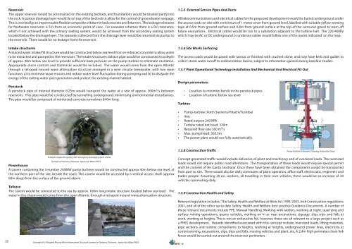
ReservoirThe upper reservoir would be constructed on the existing bedrock, and foundations would be blasted partly intothe rock. A porous drainage layer would lie on top of the bedrock to allow for the control of groundwater seepage.This is overlaid by an impermeable flexible composite of bituminised concrete and bitumen. The leakage tolerancefor freshwater reservoirs is 5l/s from an economic point of view. For seawater schemes there is a 0l/s tolerance,which if not achieved with the primary sealing system, would be achieved from the secondary sealing systemlocated below the drainage layer. The seawater collected from the drainage layer would be returned via pumps tothe reservoir. There would be no leakage from the reservoir.Intake structuresA sluiced water intake/fill structure would be constructed below sea level from re-inforced concrete to allow waterto be extracted and pumped to the reservoirs. The intake structures tailrace pipe would be constructed to a depthof approx. 40m below sea level to provide sufficient back pressure on the pump-turbine to eliminate cavitation.Appropriate sluice controls and trashracks would be included. The water would come from the open Atlanticthrough a tetrapod mound wave attenuation structure arranged in a semi circular breakwater, with two mainfunctions: a) to minimise wave erosion and reduce water level fluctuation during pumping and b) to dissipate theenergy of the exiting water post generation and protect the existing marine habitat.PenstockA penstock pipe of internal diameter 8.25m would transport the water at a rate of approx. 360m 3 /s betweenreservoirs. This pipe would be constructed by tunnelling underground, minimising environmental disturbances.The pipe would be composed of reinforced concrete tunnelway 840m long.1.3.5 External Service Pipes And DuctsAll telecommunications and electrical cables for the proposed development would be buried underground underthe access roads on site with a minimum of 1 meter cover from ground level, labelled with suitable yellow warningtape at 0.5m from ground surface and 0.8m from ground surface at the top of the surround gravel to warn offfuture excavations. Electrical cables would be run to a substation adjacent to the turbine hall. The 220/400kVwhich may be AC or DC underground or undersea cables would follow one of the routes indicated on the map.1.3.6 Site Works SurfacingThe access roads would be paved with tarmac or finished with crushed stone, and may have kerb and gullies tocollect storm water runoff to sedimentation basins, subject to information gained during baseline studies.1.3.7 Plant Operational Technology Installation And Mechanical And Electrical Fit-OutDesign parameters:• Location to minimize bends in the penstock pipes• Location of turbine below sea levelTurbine• Pump-turbine (Voith Siemens/Hitachi/Toshiba)• 4no.• Rated output: 240 MW• Turbine rated net head: 330m• Required flow rate 360 m³/s• Max. pump Head: 302.5m• The power plant would run fully automatically.1.3.8 Construction TrafficPump Turbine Schematic Drawing (Indicative Only)22Example inspection gallery with emergency drainage system visible,located at Yanbaru, Okinawa, Japan Sea Water PHES<strong>Power</strong>houseA cavern containing the 4 number 240MW pump turbines would be constructed approx 40m below sea level, atthe northern part of the site, beside the coast. This cavern would be accessed by a vertical access shaft (approx60m deep) from the surface of the ground above.TailraceThe cavern would be connected to the sea by approx. 100m long intake structure located below sea level. Thewater in the chasm would come from the open Atlantic through a tetrapod mound wave attenuation structure.Example of a Tetrapod Mound Wave Attenuation Structure, located at Yanbaru, Okinawa, Japan Sea Water PHESConcept generated traffic would include deliveries of plant and machinery and of oversized loads. The oversizedloads would not require public road alterations. The transportation of these loads would require special permitand the consent of ‘An Garda Siochana’. Once these have been obtained the components would be transportedfrom port to site. There would also be daily commutes of plant operators, office staff, electricians, engineers andtrades people. Assuming 20 no. workers, all travelling in their own vehicles, there would be an increase of 20vehicles commuting daily.1.3.9 Construction Health and SafetyRelevant legislation includes, ‘The Safety, Health and Welfare at Work Act 1993-2003, Irish Construction regulations2001, and all of the other up to date Safety, Health and Welfare best practice Guidance Documents. A number ofthese relevant documents include PPE, Manual Handling, Working with ladders, working at night, quarrying andsurface mining operations, quarry vehicles, working on in or near excavations, signage, slips trips and falls atwork, working at heights. This is not an exhaustive list, however, these are all relevant to a large project such asa PHES development. Hazards identified associated with this concept include, oversized loads, lifting materials,pipe sections and turbine components to heights, working at heights, underground power lines, electricity atcommissioning, excavations, slips, trips and falls, moving vehicles and plant, etc. A 2.4m high perimeter chain linkfence would be carried out around the reservoir perimeters.