RT-1000 Product Info
RT-1000 Product Info
RT-1000 Product Info
- No tags were found...

You also want an ePaper? Increase the reach of your titles
YUMPU automatically turns print PDFs into web optimized ePapers that Google loves.
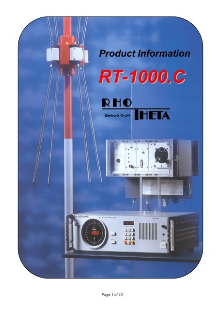
<strong>Product</strong> <strong>Info</strong>rmation<strong>RT</strong>-<strong>1000</strong>.CPage 1 of 10
Edited by:RHOTHETA Elektronik GmbHKemmelparkDr.-Ingeborg-Haeckel-Str. 282418 MurnauGermanyTel.: +49 8841 4879 - 0Fax: +49 8841 4879 - 15Internet:E-Mail:www.rhotheta.deemail@rhotheta.deCopyright © RHOTHETA Elektronik GmbHAll rights reservedIssue: [2009/08/27] [Rev 1.01]Note:The manufacturer reserves the right on making modifications of the product described hereinat any time and without previous information.Page 2 of 10
1 General <strong>Info</strong>rmationThe <strong>RT</strong>-<strong>1000</strong> direction finder system is designed specifically for ATC and VTS applicationsand complies with ICAO and DFS (Deutsche Flugsicherung) requirements. The <strong>RT</strong>-<strong>1000</strong> isused as an ATC navigation aid that allows controllers on the ground to transmit QDMs to thepilot or verify position reports received from aircraft. Bearing information can also beintegrated into a radar screen, which makes it possible to immediately assign radiomessages to the right targets on the radar display.The <strong>RT</strong>-<strong>1000</strong> is also suitable for stationary VTS applications.1.1 Characteristics- High-precision Doppler direction finder- Extremely high rotation frequency for fast signal processing- Compact antenna system for simple installation- Antenna location independent of controller workstation- No infrastructure required for remote operation- Maintenance-friendly modular construction- RS-232 interface to permit system integration- Frequency range:Aviation band: 118.000 ... 136.975 MHzMarine band: 156.000 ... 174.000 MHz- Various scanning modes- Two or more simultaneous channels optionally available1.2 Description of the System1.2.1 Antenna Mast (Option)The special Mast <strong>RT</strong>A 1306 is recommended for the antenna system.The mast has a fixture which makes it possible to tilt the antenna downto working level to facilitate assembly and maintenance of the antenna.The integrated rotating stand makes it possible to rotate the antenna in10° steps to effectively check the direction finding system. In addition,there is a weatherproof housing for the receiver unit.Page 3 of 10
1.2.2 Flexible System ConfigurationAll known radio direction finding methods are based on the utilization of the electromagneticwave field generated by the transmitter to be found. Good results are only possible if thiswave field at the direction finding position is largely undisturbed. Regrettably, incoming wavefields are distorted significantly in the tower area due to reflections and shadows fromsurrounding buildings. Even large and costly antenna systems can only solve theseproblems, resulting from physical facts, unsatisfactorily.With "remote operation" the direction finder system <strong>RT</strong> <strong>1000</strong> realizes a concept permitting anantenna position to be chosen, which is almost totally independent from the controller'sposition. Hence, the antenna with its weatherproof receiver unit may be installed at a locationwithin the airport area which is optimal for direction finding. The connection to the controller ismade through a 6-wire line. Expensive equipment and costly infrastructures are eliminated incontrast to usual direction finding systems.The Direction Finder System <strong>RT</strong> <strong>1000</strong> realizes an equipment family which can be utilized in aflexible manner. Apart from the advantage of being service-friendly, the consequent modulardesign makes it possible to have several system components variously equipped, so that theoptimum system configuration is available with a minimum of equipment, depending on theapplication. There are four major variants for the traffic direction finding area.Configuration CThe system operates in "remote mode". The direction finding antenna is installed remotelyfrom the controller, at a location favourable for direction finding. Receiver, demodulator andantenna control module are integrated in the receiver unit located at the antenna position.They are connected to the controller by means of a 6-wire line.Application: For applications, where the evaluation position does not provide for satisfactorydirection finding conditions.Antenna System<strong>RT</strong>A 1300.AAntennaControlRF Cable6-wire Cablemax. 3.5 kmController<strong>RT</strong>C 1100.AReceiver Unit<strong>RT</strong>R 1200.APage 4 of 10
2 Technical Data2.1 Electric CharacteristicsFrequency range air band 1) :Frequency range marine band 1) :Operating channels air band:Channel pattern:Bearable kinds of modulation:System accuracy 2) :Sensitivity 3) :Polarisation:118 to 136.975 MHz156 to 174.000 MHz760; 10 preselected25 kHzA3E, F3E, A2X (ELT modulation)±2° RMS (with antenna)±1° RMS (on request)≤2 µV / m (without antenna amplifier)verticalPolarisation error: ≤1° (with field vector rotation up to 45°)Garbling cone:approx. 35° referred to the verticalPower supply:AC:115 / 230 V ±15 %; 47 to 63 HzDC:24 V -10 % / +20 %;automatic switch-over to DC voltage in caseof AC mains failurePower consumption: Controller unit: max. 15 VATemperature ranges:Receiver unit max. 10 VAOperating temperature:Antenna-40° to +80° CReceiver unit -40° to +60° CController unit -20° to +55° CInterfaces:Storage temperature: -40° to +60° Cserial V.24 (RS-232-C)parallelPage 5 of 10
Bearing display: A:Digital3 digits with 7-segment LED indicatorResolution 1°Bearing reference QDRUpdating rate approx. one indication / sBearing display response time:Monitoring:Ground transmittersuppression:B:Dual compass dial 2 concentrical circles of LED pointsResolution 10°Bearing reference QDRUpdating rate:Outer circle approx. one indication / sInner circle 47 indications / s≤ 0.3 sBuilt-in speakerModulation mode A3EMonitor output approx. 500 mW 4 to 8 ΩLine output 600 Ω, balanced, 0 dBm, m = 0.6with external contact to groundNotes:1) Not for configuration B (dependent on the type of receiver).2) For undistorted wave reception and sufficient field strength. Measurement is made atconstant frequency by changing the angle of incidence; in order to exclude site errors,angle variation is done by rotating the DF antenna on a rotator.3) System sensitivity for ±1° bearing fluctuations (cable attenuation of less than 2 dBbetween antenna and the receiver, received signal vertically polarised).Page 6 of 10
2.2 Mechanical Characteristics2.2.1 ControllerCasing:Weight:Dimensions (H x W x D):19"-desk-top model 3 UH7.2 kg132.5 x 448 x 370 mm482.6465.1180385230425.8448Page 7 of 10
2.2.2 Receiver unitCasing: Non-metallic cabinet for wall mounting (IP 65)Weight:6.5 kgDimensions (H x W x D):250 x 340 x 285 mm307337323140112031201 12051204DF-Signal 1OK +5V+15V-15V220Power Select115/230VCDf-f+SquelchIFR/L offAntennaControl4SQONOFFVOL STORE3 2 COM1A5.5281Page 8 of 10
2.2.3 Antenna SystemDimensions (Diameter x H)Weight:Lateral thrust due to wind withconstant wind speed:400 x 1120 mm400 x 3400 mm (with lightning rod and mast)3.6 kg150 km / h approx. 135 N180 km / h approx. 195 N(data with lightning rod and mast)41040 +1-0Page 9 of 10
3 Supplied accessories- Set of antenna cables- AC cable- Operating instructions- Adapter for rack installation of controller- Interface connector- Antenna rod- Lightning rod4 Options- Special antenna mast- Mast extension- Hazard light- Dummy antenna- Service kit- Service manual- Slave display- Set of cables- Antenna amplifier- DC heating for receiver unitPage 10 of 10