FinFET and other New Transistor Technologies
FinFET and other New Transistor Technologies
FinFET and other New Transistor Technologies

Create successful ePaper yourself
Turn your PDF publications into a flip-book with our unique Google optimized e-Paper software.
<strong>FinFET</strong> <strong>and</strong> <strong>other</strong> <strong>New</strong><br />
<strong>Transistor</strong> <strong>Technologies</strong><br />
Chenming Hu<br />
Univ. of California<br />
Chenming Hu, July 2011
May 4 2011 NY Times Front Page<br />
NY Times news article:<br />
• Intel will use 3D <strong>FinFET</strong> for 22nm<br />
• Most radical change in decades<br />
• There is a competing SOI technology<br />
Chenming Hu, July 2011<br />
2
Other Background Info<br />
• TSMC, IBM…new transistors soon<br />
• Since 2001 ITRS shows <strong>FinFET</strong> <strong>and</strong><br />
ultra-thin-body UTB-SOI as the two<br />
successor MOSFETs<br />
• SOITEC UTB-SOI recently available<br />
• IBM 2009 5nm UTB SOI paper<br />
Chenming Hu, July 2011<br />
3
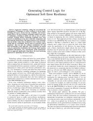
<strong>New</strong> MOSFET Structures<br />
Chenming Hu, July 2011<br />
Cylindrical FET<br />
Ultra Thin Body SOI<br />
4
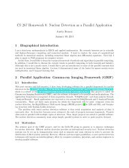
Good Old MOSFET Nearing Limits<br />
Vt, S (swing) <strong>and</strong> Ioff<br />
are sensitive to Lg &<br />
dopant variations.<br />
• high design cost<br />
• high Vdd, hence<br />
high power usage<br />
Finally painful enough for change.<br />
Chenming Hu, July 2011<br />
5
Power Consumption Problems<br />
1.Not just a chip <strong>and</strong> package thermal<br />
issue.<br />
2.ICs use a few % of world’s electricity<br />
today <strong>and</strong><br />
• Power per chip is growing.<br />
• IC units in use also growing.<br />
3.If power consumption is not reduced,<br />
industry future growth is at risk.<br />
Chenming Hu, July 2011
Want Low Vt <strong>and</strong> Low Ioff<br />
Need smaller<br />
S <strong>and</strong> less<br />
variations of<br />
S <strong>and</strong> V t<br />
Chenming Hu, July 2011<br />
7
MOSFET becomes “resistor” at very<br />
small L –- Drain competes with Gate to<br />
control the channel barrier.<br />
Drain Current, I DS (A/µm)<br />
10 -3<br />
10 -5<br />
10 -7<br />
10 -9<br />
10 -11<br />
How V t Variation & S Got So Bad<br />
Smaller Size<br />
size shrink<br />
or larger Vd<br />
0.0 0.3 0.6 0.9<br />
Gate Voltage, V GS (V)<br />
L<br />
Gate<br />
C g<br />
Insulator<br />
Source Drain<br />
Chenming Hu, July 2011<br />
C d
Reducing EOT is Not Enough<br />
Gate<br />
Source Drain<br />
Leakage Path<br />
Gate cannot control the<br />
leakage current paths<br />
that are far from the gate.<br />
Chenming Hu, July 2011
One of Two Ways to Better V t <strong>and</strong> S<br />
The gate controls a thin body from<br />
more than one side. Gate Length<br />
Gate<br />
Source Drain<br />
Gate<br />
<strong>FinFET</strong> body is a<br />
�<br />
thin fin N. Lindert et al., DRC paper II.A.6, 2001<br />
Chenming Hu, July 2011<br />
Source<br />
Drain<br />
Fin Height<br />
Fin Width
<strong>FinFET</strong>- 1999<br />
Undoped Body. 30nm etched thin fin.<br />
Vt set with gate work-function (SiGe).<br />
0.6<br />
0.4<br />
0.2<br />
0.0<br />
-0.2<br />
-0.4<br />
-0.6<br />
X. Huang et al., IEDM, p. 67, 1999<br />
Chenming Hu, July 2011<br />
ΔVt [V]<br />
Vt at 100 nA/μm, Vd = 0.05 V<br />
Fin width: 20 nm<br />
0 10 20 30 40 50<br />
Lg [nm]
State-of-the-Art <strong>FinFET</strong> on Buk Si<br />
STI<br />
Si<br />
Gate<br />
STI<br />
Chenming Hu, July 2011<br />
28nm SoC<br />
C.C. Yeh et al.,<br />
2010 IEDM<br />
20nm Hi Perf<br />
C.C. Wu et al.,<br />
2010 IEDM
<strong>FinFET</strong> is “Easy” to Scale<br />
10nm Lg AMD<br />
2002 IEDM<br />
5nm Lg TSMC<br />
2004 VLSI Symp<br />
L g =<br />
5 nm<br />
because leakage is well suppressed if<br />
Fin thickness =or< Lg<br />
• Thin fin can be made with the same Lg<br />
patterning/etching tools.<br />
Chenming Hu, July 2011<br />
3nm Lg KAIST<br />
2006 VLSI Symp
Second Way to Better V t <strong>and</strong> S<br />
Ultra-thin-body SOI (UTB-SOI) �<br />
No leakage path far from the gate.<br />
Gate<br />
Source Drain<br />
UTB<br />
SiO2<br />
Si<br />
Y-K. Choi, IEEE EDL, p. 254, 2000<br />
Drain Current [A/um]<br />
1.E-02<br />
1.E-04<br />
1.E-06<br />
1.E-08<br />
1.E-10<br />
1.E-12<br />
Chenming Hu, July 2011<br />
T si=8nm<br />
T si=6nm<br />
T si=4nm<br />
0 0.2 0.4 0.6 0.8 1<br />
Gate Voltage [V]
Most Leakage Flows >5nm Below Surface<br />
Y-K. Choi et al., IEEE Electron Device Letters, p. 254, 2000<br />
Chenming Hu, July 2011
Silicon Body Needs to be
UTB-SOI<br />
3nm Silicon Body, Raised S/D<br />
Y-K. Choi et al, VLSI Tech. Symposium, p. 19, 2001<br />
Chenming Hu, July 2011
State-of-the-Art 5nm<br />
Thin-Body SOI<br />
Chenming Hu, July 2011<br />
ETSOI, IBM<br />
K. Cheng et al, IEDM, 2009
Both Thin-Body <strong>Transistor</strong>s Provide<br />
• Better swing.<br />
• S & Vt less sensitive to Lg <strong>and</strong> Vd.<br />
• No r<strong>and</strong>om dopant fluctuation.<br />
• No impurity scattering.<br />
• Less surface scattering (lower Eeff).<br />
•Higher on-current <strong>and</strong> lower leakage<br />
•Lower Vdd <strong>and</strong> power consumption<br />
•Further scaling <strong>and</strong> lower cost<br />
Chenming Hu, July 2011
Back-Gate Bias Option<br />
UTB-SOI <strong>FinFET</strong><br />
Gate 1<br />
STI<br />
Chenming Hu, July 2011<br />
Si<br />
STI<br />
Gate 2
Similarities<br />
• 1996: UC Berkeley proposed to DARPA two<br />
“25nm <strong>Transistor</strong>s”. Both of them<br />
•use body thickness as a new scaling parameter<br />
•can use undoped body for high µ <strong>and</strong> no RDF<br />
• 1999: demonstrated <strong>FinFET</strong><br />
2000: demonstrated UTB-SOI (Ultra-Thin Body)<br />
• Since 2001: ITRS highlights <strong>FinFET</strong> <strong>and</strong> UTBSOI<br />
• Now: Intel will use Trigate <strong>FinFET</strong>.<br />
Soitec readies +-0.5nm substrates for UTBSOI<br />
• Both <strong>FinFET</strong> & UTBSOI better than planar bulk!<br />
Chenming Hu, July 2011
Main Differences<br />
• <strong>FinFET</strong> body thickness ~ Lg. Investment by fabs<br />
UTBSOI thickness ~1/3 Lg. Investment by Soitec<br />
• <strong>FinFET</strong> has clear long term scalability. UTBSOI<br />
may be ready sooner depending on each firm’s<br />
readiness with <strong>FinFET</strong>.<br />
• <strong>FinFET</strong> has larger Ion or can use lower Vdd.<br />
UTBSOI has a good back-gate bias option.<br />
UTBSOI<br />
<strong>FinFET</strong><br />
Chenming Hu, July 2011<br />
Gate 1 Gate 2<br />
Si<br />
STI<br />
STI
What May Happen<br />
• <strong>FinFET</strong> will be used at 22nm by Intel <strong>and</strong> later<br />
by more firms through <strong>and</strong> beyond 10nm.<br />
• Some firms may use UTBSOI to gain/protect<br />
market at 20 or 18nm if <strong>FinFET</strong> is not option.<br />
If so, competition between <strong>FinFET</strong> <strong>and</strong> UTBSOI<br />
will bring out the best of both.<br />
If not----- back to first bullet.<br />
Chenming Hu, July 2011
Chenming Hu, July 2011
Drain Current (A)<br />
<strong>FinFET</strong> BSIM Compact Model Verified<br />
�<strong>FinFET</strong> Fabricated at TSMC.<br />
�Lg = 30 nm-10um<br />
50µ<br />
25µ<br />
Id-Vg 1m I<br />
Lg = 50nm<br />
Lg = bulk 50nm<br />
Vd = 50mV<br />
Vd = 1.2V<br />
0<br />
1p<br />
0.0 0.4 0.8 1.2<br />
Gate Voltage (V)<br />
1µ<br />
1n<br />
Bulk Current (A)<br />
100p<br />
10p<br />
Vd = 1.2V<br />
1p<br />
0.0 0.4 0.8 1.2<br />
Gate Voltage (V)<br />
Chenming Hu, July 2011<br />
Drain Current (µA)<br />
50 Lg = 50nm<br />
Vg = 1.2 - 0.4V<br />
25<br />
Id-Vd<br />
Id-Vd<br />
0<br />
0.0 0.4 0.8 1.2<br />
Drain Voltage (V)<br />
M. Dunga, 2008 VLSI Tech Sym
Chenming Hu, July 2011
Chenming Hu, July 2011
Chenming Hu, July 2011
Chenming Hu, July 2011
Reduce C<br />
f ⋅C<br />
⋅<br />
Vdd<br />
Reduce all capacitances.<br />
2<br />
Chenming Hu, July 2011<br />
30
Vacuum-Sheath Interconnect<br />
� C TOTAL ∝ Delay, C M ∝ Crosstalk Noise<br />
Dielectric Beam<br />
Etch Stop layer<br />
Metal<br />
Chenming Hu, July 2011<br />
Load Capacitance : C O<br />
Mutual Capacitance : C M<br />
Total Capacitance : C TOTAL<br />
J. Park, Electronics Letters, p. 1294, 2009
Effective k of Vacuum-Sheath<br />
Interconnects<br />
Beam Dielectric Constant<br />
2.25<br />
2.9<br />
3.3<br />
3.6<br />
3.9<br />
1.9<br />
2.0<br />
2.1<br />
2.3 2.2<br />
2.4<br />
2.5<br />
No Solution<br />
2.6<br />
1.8<br />
No Solution<br />
1.7<br />
20 30 40 50 60 70 80<br />
Air Percentage (%)<br />
1.6<br />
1.4<br />
1.5<br />
1.3<br />
J. Park, Electronics Letters, p. 1294, 2009<br />
Chenming Hu, July 2011
Vacuum Spacer to Reduce C GC<br />
� C GOX : Gate Oxide Capacitance<br />
� C GC : Gate-to-Contact Capacitance<br />
C GOX<br />
» CGC CGOX < CGC Gate<br />
Chenming Hu, July 2011<br />
Contacts<br />
Scale Down
Vacuum Spacer Self-Aligned Contact<br />
20nm MOSFET comparison<br />
Oxide<br />
Vacuum<br />
Inverter<br />
Delay, ps<br />
Inverter<br />
switching<br />
energy, fJ<br />
Relative<br />
Area<br />
Chenming Hu, July 2011<br />
Oxide<br />
Spacer<br />
6.15<br />
(1)<br />
24.2<br />
(1)<br />
Vacuum<br />
Spacer<br />
Selfaligned<br />
contact<br />
(SAC)<br />
5.05<br />
(0.82)<br />
18.8<br />
(0.78)<br />
1 0.7<br />
J. Park, IEEE EDL, p.1368, 2009
Future Low Voltage Green <strong>Transistor</strong><br />
Log Drain Current I d<br />
S60mV/dec<br />
Gate Voltage V g<br />
Chenming Hu, July 2011<br />
35
How to reduce V dd to 0.15V?<br />
1.Reduce Vdd – Vt to < 0.1V with high-<br />
mobility-channel material, or sub-<br />
threshold circuits.<br />
2. Reduce V t to 50mV. Need a device<br />
that is free of the 60mV/decade<br />
turn-off limit.<br />
Chenming Hu, July 2011
Origin of the 60mV/decade Limit<br />
A potential<br />
barrier controls<br />
the electron flow.<br />
E c<br />
E v<br />
C OX<br />
Leakage current is determined by Boltzmann<br />
distribution or 60 mV/decade, limiting MOSFET, bipolar,<br />
graphene MOSFET…<br />
So, let electrons go through, not over, the<br />
energy barrier � semiconductor tunneling<br />
or MEMS<br />
V G<br />
Source Channel Drain<br />
Chenming Hu, July 2011
E C<br />
E V<br />
Semiconductor B<strong>and</strong>-to-B<strong>and</strong> Tunneling:<br />
generating electron/hole pairs<br />
A known mechanism of leakage current since<br />
1985.<br />
Called Gate Induce Drain Leakage (GIDL).<br />
Chenming Hu, July 2011<br />
N+ P-<br />
N+<br />
J. Chen, P. Ko, C. Hu, IEDM 1985
P+ Pocket<br />
S<br />
P+<br />
Pocket<br />
G<br />
N+ N- P+ -<br />
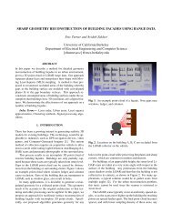
Green <strong>Transistor</strong> --Simulation<br />
Buried Oxide<br />
Gate<br />
Energy Electron b<strong>and</strong> flow diagram<br />
N+ Source<br />
D<br />
Hole flow<br />
Simulated carrier generation rates<br />
P+ Drain<br />
C. Hu, 2008 VLSI-TSA, p.14, April, 2008<br />
Abrupt turn-on due to over-lap of valence/conduction<br />
b<strong>and</strong>s; adjustable turn-on voltage.<br />
C. Hu, 2008 VLSI-TSA, p.14, April, 2008<br />
Chenming Hu, July 2011
I DS (µ/µm)<br />
Reduce Vdd by Reducing Eg<br />
1E-02<br />
1E-03<br />
1E-04<br />
1E-05<br />
1E-06<br />
1E-07<br />
1E-08<br />
1E-09<br />
1E-10<br />
1E-11<br />
Simulated impact of Eg scaling<br />
Eg=0.36eV, Vdd=0.2V, EOT=5 Å, CV/I=0.42pS<br />
Eg=0.69eV, Vdd=0.5V, EOT=7 Å, CV/I=2.2pS<br />
Eg=1.1eV, Vdd=1V, EOT=10 Å, CV/I=4.2pS<br />
Eg=0.36eV<br />
Eg=0.69eV<br />
Eg=1.1eV<br />
Lg=40nm<br />
0.0 0.2 0.4 0.6 0.8 1.0<br />
Gate Voltage, V GS (V)<br />
Vdd scales down faster than Eg.<br />
Chenming Hu, July 2011<br />
C. Hu, 2008 VLSI-TSA, p.14, April, 2008
Simulated gFET Inverter VTC<br />
Good voltage gain at 0.1V<br />
Output Voltage, V OUT (mV)<br />
.<br />
200<br />
150<br />
100<br />
50<br />
0<br />
VDD: 0.2 V<br />
VDD: 0.15 V<br />
VDD: 0.1 V<br />
0 50 100 150 200<br />
Input Voltage, V IN (mV)<br />
Chenming Hu, July 2011<br />
C. Hu, 2008 VLSI-TSA, p.14, April, 2008
Gate<br />
P+ Source N+ Drain<br />
Ge Substrate<br />
Hetero-junction gFET<br />
• Strained Si on Ge has 0.18eV “effective<br />
tunneling Eg”.<br />
• III-V.<br />
Si<br />
Gate<br />
~<br />
~<br />
Gate Oxide<br />
~<br />
~<br />
Si Ge<br />
E C offset<br />
E C<br />
E V<br />
Ge tFET<br />
Si-Ge HtFET<br />
A. Bowonder, Intern’l Workshop Junction Tech., 2008<br />
Chenming Hu, July 2011
• <strong>FinFET</strong> <strong>and</strong> UTB-SOI are viable new<br />
sub-22nm transistors.<br />
• Different performances, investment<br />
costs, wafer costs, scaling barriers.<br />
• Their BSIM SPICE models are<br />
available – free �<br />
Summary<br />
• Capacitance <strong>and</strong> tunnel gFET are<br />
potential opportunities.<br />
Chenming Hu, July 2011<br />
43